Marantz SC-7S2 Service Manual
Hide thumbs
Also See for SC-7S2:
- User manual (26 pages) ,
- Brochure & specs (4 pages) ,
- Specification sheet (2 pages)
Table of Contents
Advertisement
Quick Links
Service
Manual
SECTION
1. TECHNICAL SPECIFICATIONS ........................................................................................... 1
2. CAUTION .............................................................................................................................. 1
3. SERVICE MODE .................................................................................................................. 2
4. UPDATE FIRMWARE ........................................................................................................... 4
[A] SOFTWARE (fdtv306r00.exe) DOWNLOADS AND INSTALLS PROCEDURE ............. 4
[B] WRITING AND UPDATE SOFTWARE ..........................................................................31
5. BLOCK DIAGRAM .............................................................................................................. 42
6. WIRING DIAGRAM ............................................................................................................. 43
7. SCHEMATIC DIAGRAM .................................................................................................... 45
8. PARTS LOCATION ............................................................................................................. 53
9. EXPLODED VIEW AND PARTS LIST ................................................................................ 69
10. IC DATA ............................................................................................................................... 73
11. ELECTRICAL PARTS LIST ................................................................................................. 79
12. ABOUT REPLACE THE MICROPROCESSOR WITH A NEW ONE .................................. 93
Please use this service manual with referring to the user guide ( D.F.U. ) without fail.
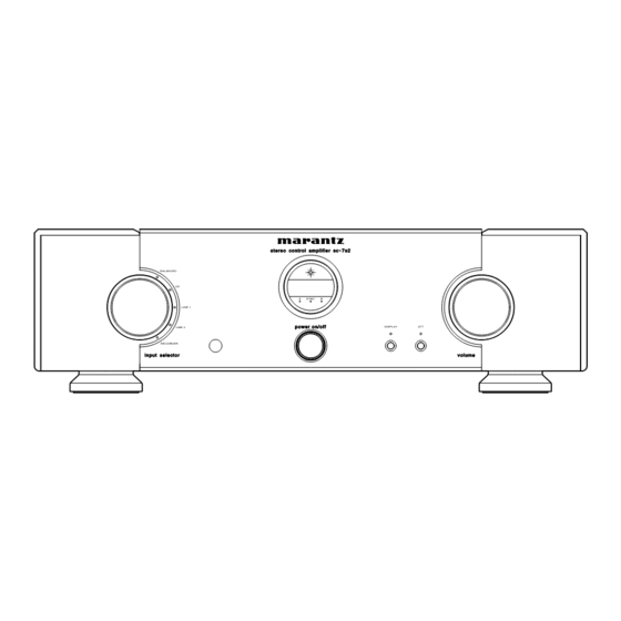
st ere o co n tr o l a mp lifi e r s c- 7s 2
BALANCED
CD
SYNC
B
A
LINE 1
p ow e r o n/ o ff
LINE 2
RECORDER
i np u t sel ect o r
TABLE OF CONTENTS
SC-7S2
SC-7S2 /
F N/K1G/N1G/U1G
Stereo Control Amplifi er
DISPLAY
ATT
vol um e
PAGE
Part no. 90M340J855010
First Issue 2006.09
MZ
Advertisement
Table of Contents

Related Manuals for Marantz SC-7S2


Summary of Contents for Marantz SC-7S2
-
Page 1: Table Of Contents
Service SC-7S2 / F N/K1G/N1G/U1G Manual Stereo Control Amplifi er st ere o co n tr o l a mp lifi e r s c- 7s 2 BALANCED SYNC LINE 1 p ow e r o n/ o ff DISPLAY... - Page 2 MARANTZ Parts for your equipment are generally available to our National Marantz Subsidiary or Agent. ORDERING PARTS : Parts can be ordered either by mail or by Fax.. In both cases, the correct part number has to be specifi ed.
-
Page 3: Technical Specifications
1. TECHNICAL SPECIFICATIONS DIMENSIONS Audio Characteristics Rated Output (20Hz - 20kHz) ..............1.7V (Balanced) ............... 1.7V (Unbalanced) Maximum Output (20Hz - 20kHz) ..............13.5V (Balanced) ............. 13.5V (Unbalanced) Total Harmonic Distortion (20Hz - 20kHz) .............0.0015% (Balanced) ............0.003% (Unbalanced) Frequency Response (+0/-3dB) ............ 3 Hz - 150 kHz(Balanced) .......... -
Page 4: Service Mode
3. SERVICE MODE 3. SERVICE MODE 1. To enter the Service Mode, press the POWER switch with 本体の DISPLAY ボタンと ボタンを押しながら、 pressing the DISPLAY and ATT buttons on the main unit POWER スイッチを押して電源を にしてください。 to switch power ON, or when the remote code "166363" または、電源... - Page 5 Unit Button Displayed text 7-Seg Front Display Front PHONO BALANCE LINE 1 LINE 2 RECORDER 1 RECORDER 2 Volume UP Volume Down Display Trim EXIT Down Right Left 11. This completes all the tests. Press the DISPLAY and ATT これで確認が全て終了しましたので、さらに DISPLAY ボタ...
- Page 6 Error Messages エラーメッセージ Switch power OFF if any of the following error messages are リモートコントロール端子を用いてバス接続し、本機を複数台 displayed while multiple units are in use and connected to 使用した時に、以下のようなエラー表示が出たら電源を に the bus via the remote terminal. して、下の表にしたがって確認してください。 Error 表示 意味 対策 Meaning Measures required code ID No.2 に設定された...
- Page 7 Bus Connection System Data Flow Master ON Master ON Relay Relay -12V Q274 L274 +12V -12V - 12V -12V S274(ID SW) +12V Q201 L275 L273 M-GND Power ON Q276 Q275 M-GND Relay x 2 -12V Master_H END Relay Return-c Return-H IN-C IN-H BUS IN...
-
Page 8: Update Firmware
4. UPDATE FIRMWARE 4. UPDATE FIRMWARE [A] SOFTWARE (fdtv306r00.exe) DOWNLOADS [A] SOFTWARE (fdtv306r00.exe) DOWNLOADS AND AND INSTALLS PROCEDURE INSTALLS PROCEDURE [A-1] DOWNLOADS OF THE SOFTWARE [A-1] DOWNLOADS OF THE SOFTWARE (Flash Development Toolkit: the rest is FDT) (Flash Development Toolkit: 以下... - Page 9 4. A login ID is necessary to download the FDT. 4. FDT のダウンロードには Login ID が必要になります。 既に Login ID を持っている方は手順の へ進んでくださ If you have Login ID, please advance to step 15. If you do not have Login ID, Click the MY RENESAS. い。...
- Page 10 5. Click the If you are a new user click here to register 5. If you are a new user click here to register now をクリ now . ックします。...
- Page 11 6. Choose Non Secure or Secure in Security Level at your 6. PC のネットワーク環境により Choose Security Level から network environment. Non Secure 、または Secure を選んでください。 Choose English or another one in Region and Choose Region and Language から日本語をクリックしま Language. す。...
- Page 12 7. Input the each item. 各項目を記入します。 NOTE : The items displayed by a language and region 注意:下記説明は英語ですが、日本語を選んだ場合日本語 are different. で表示されます。...
- Page 13 8. If you have inputted the necessary items, check the I 必須項目を入力したならば、同意しますにチェックを入 れ、送信をクリックします。 Agree, and click the Submit.
- Page 14 9. The input is needless in this page. このページは入力しなくても結構です。 ページをスクロールダウンします。 Scroll down the page.
- Page 15 10. Click the Submit. 送信をクリックします。...
- Page 16 11. Immediately, an E-mail arrives from the RENESAS. 直ちに、 RENESAS から E-mail が届きます。 E-mail 内に有る登録サイトへのリンクをクリックします。 Click the link in the E-mail to go to the registration site, and input the Login ID and Password. Login ID と Password を入力し Submit をクリックします。...
- Page 17 14. Click the GLOBAL SITE. 14. GLOBAL SITE をクリックします。...
- Page 18 15. Click the Downloads in the DESIGN SUPPORT. 15. DESIGN SUPPORT 内の Downloads をクリックします。...
- Page 19 16. Type the "Flash Development toolkit" into the Download 16. Download Title に "Flash Development toolkit" を入力しま す。 Title. And click the Start Search. Start Search をクリックします。...
- Page 20 17. Click the Flash Development Toolkit of the top on the 検索結果の一番上の Flash Development Toolkit をクリッ table. クします。 NOTE : The latest edition is FDT V3.06 at present. (July, 注意:現時点 (2006 年 月 での最新バージョンは V3.06 にな 2006) It is in FDT V3.06 as follows and explains ります。以下...
- Page 21 18. Input the Login ID and Password. ダウンロードするために Login ID と Password を入力しま And click the Submit. す。 Submit. をクリックします。...
- Page 22 19. Scroll down the page. ページをスクロールダウンします。...
- Page 23 20. Check the Agree, and click the Submit. 20. Agree にチェックを入れ、 Submit をクリックします。...
- Page 24 21. Scroll down the page. ページをスクロールダウンします。...
- Page 25 22. Click the Download. 22. Download をクリックします。...
- Page 26 23. Click the Save. 23. Save をクリックします。 24. Save the fdtv306r00.exe on your PC’s hard disc. 24. fdtv306r00.exe を任意のフォルダに保存します。 NOTE : A file name is change by improvement. 注意: ファイル名はバージョンにより変わります。...
- Page 27 [A-2] INSTALLS OF THE SOFTWARE [A-2] INSTALLS OF THE SOFTWARE (Flash Development Toolkit Ver.3.06) (Flash Development Toolkit Ver.3.06) 1. Open the folder with the downloaded file. ダウンロードしたファイルのあるフォルダを開きます。 2. And double click the fdtv306r00.exe. 2. fdtv306r00.exe をダブルクリックします。 3. Click the Next. 3.
- Page 28 4. Check the International [English], and click the Next. 4. International [English] にチェックを入れ Next をクリック します。 5. Check the I accept the terms of the license agreement, 5. I accept the terms of the license agreement にチェック and Click the Next. を入れ、...
- Page 29 6 Click the Next. 6. Next をクリックします。 7. Check the all file type, and Click the Next. Next 全てのファイルタイプにチェックを入れ、 をクリック します。...
- Page 30 8. Click the Next. 8. Next をクリックします。 9. Click the Install. 9. Install をクリックします。...
- Page 31 10. The Setup Status bar appears. インストールの状態が表示されます。 11. Click the Finish. 11. Finish をクリックします。...
- Page 32 12. Click the OK. 12. OK をクリックします。...
-
Page 33: [B] Writing And Update Software
Serial ポートのあるもの downloading. • RS-232C ストレートケーブル (9Pin メス -9Pin メス • Windows PC (OS: Windows2000 or WindowsXP) with • 書き込み用データ (SC-7S2 フォルダ内 00M340J499D00 : Serial port. SC7S2_v003.mot) • RS-232C Dsub-9 pin cable (female to female/straight 注意: v003 はリリース番号。最新リリース番号は v003 で... - Page 34 3. Check the Create a new project workspace, and click リックします。 the OK. 注意: SC-7S2 用の設定が必要です。既に設定が終 NOTE : It is needs setup for SC-7S2. When you have already setup, please advance to "[2] Writing わっている方は "[2] Writing Procedure for Procedure for microprocessor". microprocessor"...
- Page 35 4. SC-7S2 is inputted into the Workspace Name. 4. Workspace Name に SC-7S2 を入力します。 (It is simultaneously inputted into Project Name.) 同時に Project Name にも入力されます Click the OK. をクリックします。 5. Choose the H8/3664F in Select Device. And click the 5. Select Device から...
- Page 36 6. Choose the Serial port number in the Select Port. And 6. Select Port から Serial ポート番号を選び、 Next をクリック click the Next. します。 7. 8.0 is inputted into the Enter the CPU crystal frequency 7. Enter the CPU crystal frequency for the selected device for the selected device.
- Page 37 8. Check The BOOT Mode in Select Connection. 8. Select Connection の BOOT Mode をチェックします。 Un-check the Use Default, and choose the 19200 in Recommended Speeds の Use Default のチェックを外 Recommended Speeds. し、 19200 を選択します。 Next をクリックします。 Click the Next. 9.
- Page 38 [2] Writing Procedure for HDMI CPU [2] Writing Procedure for microprocessor 本機のトップカバーを外します。 1. Remove the top lid of the unit. 接続冶具の RS-232C コネクタと Windows PC の Serial ポー 2. Connect the RS-232C on the connection JIG and the Serial Port of windows PC with RS-232C cable. トを...
- Page 39 8. Check the Browse to another project workspace, and 8. Browse to another project workspace をチェックし、 click OK. をクリックします。 9. workspase フォルダの下の SC-7S2 フォルダ内の SC-7S2. 9. Choose SC-7S2.AWS in SC-7S2 folder under workspase を選択し、 Open をクリックします。 folder. And Click the Open.
- Page 40 10. Right button of mouse click on the SC-7S2, and select 10. SC-7S2 を右クリックし、メニューから Add Files... をクリ the Add Files... in a menu. ックします。 11. Choose the sc7s2_v003.mot, and click the Add. 11. sc7s2_v003.mot を選択し、 をクリックします。 NOTE : The v003 is a revision number. The latest 注意:...
- Page 41 13. Click the Device in the menu bar and select the Connect 13. Device をクリックし、メニューから Connect to Device を to Device. クリックします。 14. Press right button of mouse on the sc7s2_v003.mot, and 14. sc7s2_v003.mot を右クリックし、メニューから select the Download File in a menu. Download File をクリックします。...
- Page 42 15. Software is written into the microprocessor. ソフトウェアが HDMI マイコンに書き込まれます。 The writing of software takes about 25 seconds. 書き込みにかかる時間は約 秒です。 16. Click the Device in the menu bar and select the 16. Device をクリックし、メニューから Disconnect をクリッ Disconnect. クします。...
- Page 43 17. Click the File and select the Exit in menu. 17. File をクリックし、メニューから Exit をクリックします。 18. Press the power on/off button for turn off the unit. 18. power on/off ボタンを押し、本機の電源を切ります。 本機から電源コードと ピンケーブルを外します。 19. Disconnect the mains cord and 4 pins connective code from the unit.
-
Page 44: Block Diagram
5. BLOCK DIAGRAM BALANCED Ach INPUT BALANCED Ach PRE OUT LINE-1 UNBALANCED-1 LINE-2 UNBALANCED-2 RECORDER REC OUT MUTE DRIVER Bch VOL INPUT SELECTOR RELAY Bch INPUT DRIVER VOLUME ATT SW DISPLAY DISPLAY SW μ- COM. ±22V DRIVER LED DISPLAY ±12V RELAY ID SW +5V... -
Page 45: Wiring Diagram
6. WIRING DIAGRAM BALANCED OUTPUT-A BALANCED INUT-A W007 W014 JE01 J003 J015 J505 BALANCED INUT-B PRE OUT-A W008 W016 J017 JE02 C001 J004 J507 C003 J019 W027 BALANCED OUTPUT-B J005 W009 W029 W015 JA01 J105 J510 P101 J016 J506 J006 00MWG340J501- J007 W010... -
Page 46: Schematic Diagram
7. SCHEMATIC DIAGRAM 22.5V DE01 +5VD +5VA P101 DE05 R557 21.3V +22V 00MWG340J501- 22.5V 0.6V 21.0V 21.0V A(+) CE15 Q505 Q509 Q537 +VCC +VCC +VCC CSB-A 47/16V RE49 MUTEB +22V +OUT +OUT +OUT 47/16V 20.4V C529 C513 -20.4V 47/16V -OUT -OUT -OUT -0.6V... - Page 47 P401 00MWG340J6010 22.5V RA23 22.5V RB23 22.5V RC23 +22V +22V +22V DA01 DB01 DC01 DA05 DB05 DC05 0.6V 0.6V 0.6V LINE-1 LINE-2 W010 JB01 W009 JA01 W011 JC01 J005 J007 J009 CC05 RC05 CC09 CA05 RA05 CA09 CB05 RB05 CB09 10/35V 10/35V 47/16V...
- Page 48 L002 TO J501 W005 J805 J802 P801 R828 R807 +32V 22.5V 00MWG340J502- 1 1/4w D801 D802 D803 D804 21DQ10 21DQ10 21DQ10 21DQ10 W801 R827 -32V +32V 1/4w +24.0 J804 W004 +32V U811 +32V (N.C) -32V C804 D805 D806 D807 D808 J801 470/25v 21DQ10...
- Page 49 PU01 P301 00MWG340J702 00MWG340J701- TO J107 Q209 Q211 Q213 Q215 Q217 J201 KTA1267 KTA1267 KTA1267 KTA1267 KTA1267 PD71 L301 L302 00MWG340J706- L303 BALANCE LINE1 LINE2 TAPE L304 VOLUME TAPE L305 W023 SU81 D301 L306 J301 J304 MUTE Q210 Q212 Q214 Q216 Q218 DTC114ES...
-
Page 50: Parts Location
8. PARTS LOCATION P101 PWB A C111 CE02 DE06 Q514 R113 R526 RE07 C151 CE03 DE07 Q515 R114 R527 RE08 C152 CE04 DE08 Q516 R115 R528 RE09 C153 CE05 DE09 Q517 R116 R529 RE10 C154 CE06 DE10 Q518 R121 R530 RE11 C155 CE07... - Page 51 鉛フリー半田 鉛フリー半田 半田付けには、鉛フリー半田 (Sn-Ag-Cu) を使用してください。 Lead-free Solder When soldering, use the Lead-free Solder (Sn-Ag-Cu).
- Page 52 P101 PWB B C513 C514 C515 C516 Q501 Q502 Q503 Q504 鉛フリー半田 鉛フリー半田 半田付けには、鉛フリー半田 (Sn-Ag-Cu) を使用してください。 Lead-free Solder When soldering, use the Lead-free Solder (Sn-Ag-Cu).
- Page 53 P401 PWB B C401 CC09 DC05 QA03 R401 RA17 RC09 RR01 C402 CC10 DC06 QA04 R402 RA18 RC10 RR02 C403 CC11 DC07 QA05 R403 RA19 RC11 RR03 C404 CC12 DC08 QA06 R404 RA20 RC12 RR04 C405 CC13 DC09 QA07 R405 RA21 RC13 RR05...
- Page 54 PU01 PWB A C201 C267 C355 J206 L308 Q223 R220 R241 R337 C202 C268 C356 J207 Q201 Q224 R221 R242 R338 C203 C269 C357 J211 Q203 Q301 R222 R243 R339 C204 C301 C358 J212 Q205 R201 R223 R244 R340 C205 C303 C359 J301...
- Page 55 PU01 PWB B Q202 P271 PWB B P261 PWB B C271 C291 Q272 R282 C361 C272 C292 Q273 R283 C362 C273 D271 Q274 R284 J262 C274 D272 Q275 R285 S261 C276 D273 Q276 R292 C277 D274 Q277 R293 C278 D275 Q278 R294 C279...
- Page 56 P801 PWB B P301 PWB B C803 D837 R814 C302 R316 C804 D838 R815 C339 R317 C805 D839 R816 C340 R318 C806 D840 R819 D301 R319 C807 D841 R820 D302 R320 C808 D842 R822 D303 R321 C809 D843 R824 D304 R322 C810 D844...
- Page 57 PD71 PWB B PS71 PWB B PU51 PWB B JU21 J278 C314 RU57 S273 D315 RU58 J303 RU59 R341 RU60 SU81 PU61 PWB B PF01 PWB B J871 C315 D316 J872 J873 J302 R342 J874 J875 PS91 PWB B C891 J891 S891 PU71 PWB B...
-
Page 58: Exploded View And Parts List
9. EXPLODED VIEW AND PARTS LIST... - Page 59 PWB ASSY ID SW PWB ASSY PS71 PWB ASSY MODE SW PWB ASSY PU01 PWB ASSY U-PRO PWB ASSY PU51 PWB ASSY R LED PWB ASSY NOTE : "nsp" PART IS LISTED FOR REFERENCE ONLY, MARANTZ WILL NOT SUPPLY THESE PARTS.
- Page 60 PACKING CASE SC-7S2 003S 00M339J809010 CUSHION CUSHION F 004S 00M339J809020 CUSHION CUSHION R 010S 00M340J805020 MASS CARTON PACKING CASE (W) W091 00MZD01000910 CONN. CORD TCP8580 REMOTE CABLE NOTE : "nsp" PART IS LISTED FOR REFERENCE ONLY, MARANTZ WILL NOT SUPPLY THESE PARTS.
-
Page 61: Microprocessor And Ic Data
10. MICROPROCESSOR AND IC DATA Q201 : HD64F3664H 48 47 46 45 44 43 42 41 40 39 38 37 36 35 34 33 P76/TMOV P14/ P75/TMCIV P15/ P74/TMRIV P16/ P57/SCL P17/ /TRGV P56/SDA PB4/AN4 PB5/AN5 H8/3664 PB6/AN6 Top view P10/TMOW PB7/AN7 P55/... - Page 62 Q201 : HD64F3664H PORT Name I/O Function Description N.C. N.C. (NMI) ICE4 Pull Up P80(FTCI) N.C. P81(FTIOA) Capture input port IR capture P82(FTIOB) VOL-CLK O Output port WM8816 Clock P83(FTIOC) VOL-DAT O Output port WM8816 Data Input / Output P84(FTIOD) Master_H O Output port BUS control...
- Page 63 Q301 : NJU3716 DATA DATA Controller Circuit SYMBOL FUNCTION Parallel Conversion Data Output Terminals Parallel Conversion Data Output Terminals Serial Data Output Terminal DATA Serial Data Input Terminal Clock Signal Input Terminal Strobe Signal Input Terminal Clear Signal Input Terminal Parallel Conversion Data Output Terminal Parallel Conversion Data Output Terminals Power Supply Terminal (2.4 to 5.5V)
- Page 64 Q302 : NJU3719 DATA DATA Controller Circuit SYMBOL FUNCTION Parallel Conversion Data Output Terminals Parallel Conversion Data Output Terminals DATA Serial Data Input Terminal Clock Signal Input Terminal Strobe Signal Input Terminal Clear Signal Input Terminal Parallel Conversion Data Output Terminals Power Supply Terminal (2.4 to 5.5V)
- Page 65 Q526/Q529 : WM8816 AVDD AGND LGND RGND DGND DVDD CCLK MUTEB DATA LGND LEFT OUT Zero Peak Crossing Level Detector Detector External Opamps WM8816 MUTEB Control DATA CCLK Zero Peak Crossing Level Detector Detector RIGHT OUT RGND AVDD AGND DVDD DGND NAME TYPE...
- Page 66 NJU3716 NJU3719 DATA DATA LED1 LED2 LED3 LED4 Pin No. Data output pin NJU3716 Pin No. Data output pin NJU3719 LED3b TAPE LED LED3c LINE-2 LED LED3-DP LINE-1 LED LED3d SACD/CD LED LED3e BALANCED LED LED3g POWER LED LED3f ATT LED LED3a B-CH LED A-CH LED...
-
Page 67: Electrical Parts List
11. ELECTRICAL PARTS LIST NOTE ON SAFETY FOR FUSIBLE RESISTOR : PARTS INFORMATION The suppliers and their type numbers of fusible resistors RESISTORS 1) 00MGD05 × × × 140, Carbon fi lm fi xed resistor, ±5% 1/4W are as follows; 2) 00MGD05 ×... - Page 68 D117 00MHD20002710 DIODE 1D3 1A/200V P101 D118 00MHD20002710 DIODE 1D3 1A/200V P101 D119 00MHD20002000 DIODE 1SS176,MA165,1SS254 30V 0.1A P101 D121 00MHD20002000 DIODE 1SS176,MA165,1SS254 30V 0.1A NOTE : "nsp" PART IS LISTED FOR REFERENCE ONLY, MARANTZ WILL NOT SUPPLY THESE PARTS.
- Page 69 00MHT109702A0 00MHT109702A0 TRS. 2SA970 GR OR BL P101 Q515 00MHT109702A0 00MHT109702A0 TRS. 2SA970 GR OR BL P101 Q516 00MHT109702A0 00MHT109702A0 TRS. 2SA970 GR OR BL NOTE : "nsp" PART IS LISTED FOR REFERENCE ONLY, MARANTZ WILL NOT SUPPLY THESE PARTS.
- Page 70 390 OHM +-5% 1/6W P101 RE23 00MGD05391160 RES. 390 OHM +-5% 1/6W P101 RE24 00MGD05391160 RES. 390 OHM +-5% 1/6W P101 RE25 00MGD05391160 RES. 390 OHM +-5% 1/6W NOTE : "nsp" PART IS LISTED FOR REFERENCE ONLY, MARANTZ WILL NOT SUPPLY THESE PARTS.
- Page 71 560 OHM +-5% 1/6W P301 R311 00MGD05561160 RES. 560 OHM +-5% 1/6W P301 R312 00MGD05561160 RES. 560 OHM +-5% 1/6W P301 R313 00MGD05561160 RES. 560 OHM +-5% 1/6W NOTE : "nsp" PART IS LISTED FOR REFERENCE ONLY, MARANTZ WILL NOT SUPPLY THESE PARTS.
- Page 72 00MOF56221540 FILM CAP. FPS-200V-221K (220PF 10%) P401 CC09 00MOA476016Z0 ELECT. CAP. ROS-16V 470M-G3#PE-T2 P401 CC10 00MOA476016Z0 ELECT. CAP. ROS-16V 470M-G3#PE-T2 P401 CC11 00MOA227025R0 ELECT. CAP. ROA-25V 221M-5#PE-T2 NOTE : "nsp" PART IS LISTED FOR REFERENCE ONLY, MARANTZ WILL NOT SUPPLY THESE PARTS.
- Page 73 00MKH339J7010 00MKH339J7010 UNIT & H-IC HDAM-SA S2 P401 Q405 00MHT109702A0 00MHT109702A0 TRS. 2SA970 GR OR BL P401 Q406 00MHT109702A0 00MHT109702A0 TRS. 2SA970 GR OR BL NOTE : "nsp" PART IS LISTED FOR REFERENCE ONLY, MARANTZ WILL NOT SUPPLY THESE PARTS.
- Page 74 68K OHM +-5% 1/6W P401 RA09 00MGD05391160 RES. 390 OHM +-5% 1/6W P401 RA10 00MGD05391160 RES. 390 OHM +-5% 1/6W P401 RA11 00MGD05391160 RES. 390 OHM +-5% 1/6W NOTE : "nsp" PART IS LISTED FOR REFERENCE ONLY, MARANTZ WILL NOT SUPPLY THESE PARTS.
- Page 75 00MHD30621000 00MHD30621000 ZENER DIODE 6.2V ZENER EQUIVALENT P801 D831 00MHD20059100 00MHD20059100 DIODE ! 21DQ10 P801 D832 00MHD20059100 00MHD20059100 DIODE ! 21DQ10 P801 D833 00MHD20059100 00MHD20059100 DIODE ! 21DQ10 NOTE : "nsp" PART IS LISTED FOR REFERENCE ONLY, MARANTZ WILL NOT SUPPLY THESE PARTS.
- Page 76 10000UF 50V FOR SC7S2 P851 C802 00MOA10905020 ELECT. CAP. 10000UF 50V FOR SC7S2 P851 D801 00MHD20059100 00MHD20059100 DIODE ! 21DQ10 P851 D802 00MHD20059100 00MHD20059100 DIODE ! 21DQ10 NOTE : "nsp" PART IS LISTED FOR REFERENCE ONLY, MARANTZ WILL NOT SUPPLY THESE PARTS.
- Page 77 10 UF M 50V RA-2 PU01 C354 00MOA10605020 ELECT. CAP. 10 UF M 50V RA-2 PU01 C355 00MOA10605020 ELECT. CAP. 10 UF M 50V RA-2 NOTE : "nsp" PART IS LISTED FOR REFERENCE ONLY, MARANTZ WILL NOT SUPPLY THESE PARTS.
- Page 78 10K OHM +-5% 1/6W PU01 R208 00MGD05104160 RES. 100K OHM +-5% 1/6W PU01 R210 00MGD05103160 RES. 10K OHM +-5% 1/6W PU01 R211 00MGD05223160 RES. 22K OHM +-5% 1/6W NOTE : "nsp" PART IS LISTED FOR REFERENCE ONLY, MARANTZ WILL NOT SUPPLY THESE PARTS.
- Page 79 00MYP07001950 PLUG IMSA-1068-05Z042 5P PU51 R341 00MGD05103160 RES. 10K OHM +-5% 1/6W L LED PWB PU61 (00MWG340J705-) PU61 D316 00MHI10040080 00MHI10040080 L.E.D. SELU1E10CXM-S BLUE LED NOTE : "nsp" PART IS LISTED FOR REFERENCE ONLY, MARANTZ WILL NOT SUPPLY THESE PARTS.
- Page 80 00MYP07001950 PLUG IMSA-1068-05Z042 5P PU61 R342 00MGD05103160 RES. 10K OHM +-5% 1/6W IR SENSOR PWB PU71 (00MWG340J703-) PU71 Q204 00MHW10004210 00MHW10004210 PHOTO UNIT RPM6936-V4 (IR SENSOR) NOTE : "nsp" PART IS LISTED FOR REFERENCE ONLY, MARANTZ WILL NOT SUPPLY THESE PARTS.
-
Page 81: About Replace The Microprocessor With A New One
12. ABOUT REPLACE THE MICROPROCESSOR WITH A NEW ONE When replaced of the U-PRO (Microprocessor) or the Flash ROM, confirm contents of the following. Pos. After Description Remark Name replaced PU01 Q201 HD64F3664H EMPTY U-PRO After replaced A : Mask ROM (With software). No need write-in of software to the microprocessor. B : Flash ROM (With software).
Need help?
Do you have a question about the SC-7S2 and is the answer not in the manual?
Questions and answers