
Summary of Contents for Current Thinking ET120
- Page 1 ET120 & ET60 Induction Loop Amplifiers Installation and Maintenance Manual Revision 1A − August 2005 Please Read Carefully Before Commencing Installation...
-
Page 2: Operation
Suitability The ET 60 and ET120 are wall mount AFILS amplifiers and are suitable for use in rooms, which require induction loop coverage, such as meeting rooms and reception areas. The ET60 and ET120 are designed to be connected to the mains through a fused spur, and are designed for “24/7”... -
Page 3: Important Safety Information
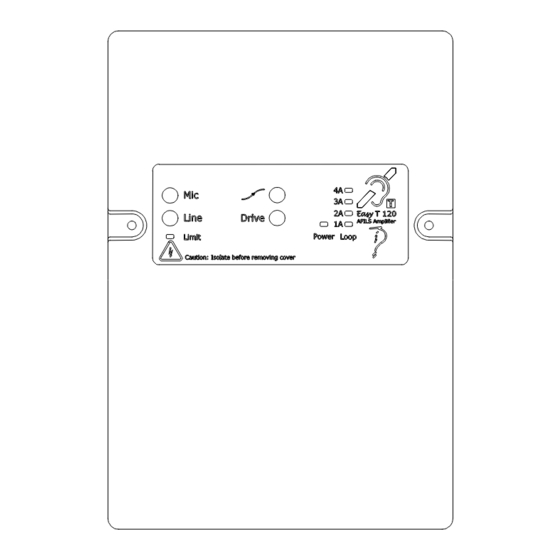
ET120 & ET60 Installation & Maintenance Manual Indications and Controls Indicators Limit The AFILS amplifier is receiving a signal at a level where the limiter is starting to operate, this LED should blink on loud peaks in the audio, if it is lit continuously the audio input is too loud and may be distorting the input stage. -
Page 4: Anti-Static Handling Guidelines
1 off 2 way Loop Screw terminal block If there are any Items missing please contact your supplier or Current Thinking Ltd, quoting the unit serial number, and the name on the packing list enclosed so we can rectify the situation. -
Page 5: Mounting The Amplifier
Mounting The Amplifier Before mounting the AFILS amplifier on the wall it is advisable to remove the cable knockouts as described above. The ET120 weighs 3KGs, so care should be taken to securely mount the unit on stud walling. Connections All wiring should come into the enclosure via the knockouts provided and be fixed tidily to the relevant terminals. -
Page 6: Mains Connection
ET120 & ET60 Installation & Maintenance Manual Mains Connection >0.75mm <2.5mm Main Amplifier Distribution Board >3mm Each amplifier requires a 3A spur, or a three-pin mains plug fitted with a 3A fuse, and wired as below: Brown Live (L) pin on the Plug and amplifier terminal block... -
Page 7: Speaker Line Input
The area covered by the ET60 & ET120 can be determined from the chart below, if the area to be covered (ET120 light grey, ET60 dark grey) has a high quantity of metal or the loop is placed at a higher level than 2.4M then a larger current will be required (approximately 20% additional current per metre in... - Page 8 Options current Drive. Mains Supply 110V operation Protection Recessed screwdriver adjust only. The ET60 & ET120 Units are designed and manufactured in the UK by: Current Thinking Ltd, Unit 91 Silver Briar Enterprise Park East, Sunderland, SR5 2TQ. www.current-thinking.com info@current-thinking.com...
Need help?
Do you have a question about the ET120 and is the answer not in the manual?
Questions and answers