Table of Contents
Advertisement
Quick Links
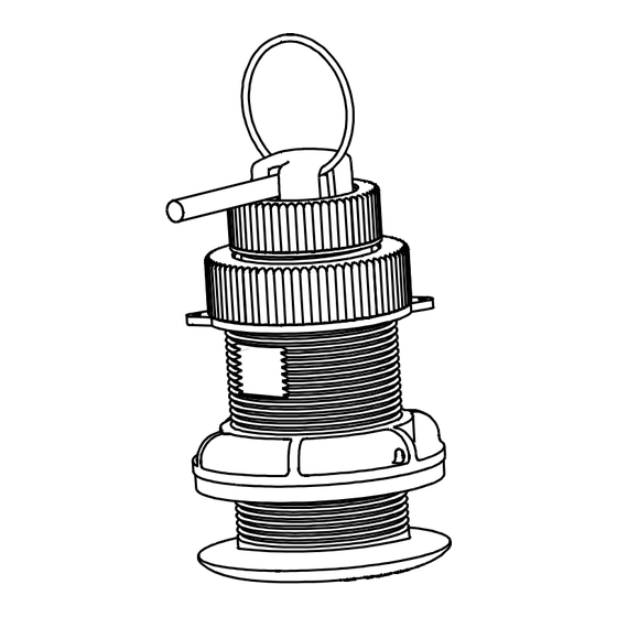
OWNER'S GUIDE & INSTALLATION INSTRUCTIONS
Thru-Hull, Retractable with Valve
Temperature or Speed & Temp. Sensor
Models: HT200, ST850
U.S. Patents: 7,110,908; 7,352,171. UK 2 409 527
Follow the precautions below for optimal
product performance and to reduce the risk of
property damage, personal injury, and/or death.
WARNING: Always wear safety goggles, a dust mask,
and ear plugs when installing.
WARNING: The valve is not a watertight seal! Always
use the insert or the blanking plug secured with the
safety wire for a watertight seal.
WARNING: The O-rings must be intact and well
lubricated to make a watertight seal.
WARNING: Always attach the safety wire to prevent
the insert or blanking plug from backing out in the
unlikely event that the cap nut fails or is screwed on
incorrectly.
WARNING: When the valve assembly is removed,
always insert the short emergency plug secured with
the CAP nut and safety wire for a watertight seal.
WARNING: Immediately check for leaks when the boat
is placed in the water. Do not leave the boat unchecked
for more than three hours. Even a small leak may allow
considerable water to accumulate.
CAUTION: Never pull, carry, or hold the sensor by its
cable; this may sever internal connections.
CAUTION: Never use a fairing with a plastic housing;
the protruding sensor would be vulnerable to damage
from impact.
CAUTION: Never install a metal housing in a vessel
with a positive ground system.
CAUTION: Never use solvents. Cleaner, fuel, sealant,
paint, and other products may contain solvents that
can damage plastic parts.
IMPORTANT: Please read the instructions completely
before proceeding with the installation. These
instructions supersede any other instructions in your
instrument manual if they differ.
Applications
• Plastic housing recommended for fiberglass or metal hulls only.
Never install a plastic housing in a wood hull since swelling of
the wood may fracture the plastic.
• Bronze housing recommended for fiberglass or wood hull only.
Never mount a bronze housing in a metal hull because
electrolytic corrosion will occur.
Record the information found on the cable tag for future reference.
Part No._________________Date___________
HT200
plastic
low profile
P17 housing
Pretest
Connect the sensor to the instrument. Check for the approximate
air temperature. If it has a paddlewheel, spin it and check for a
speed reading. If there is no reading(s) or it is inaccurate, check
the connections and try again. If there is still a problem, return the
product to the place of purchase.
Tools & Materials
Safety goggles
Dust mask
Ear plugs
Water-based anti-fouling paint (mandatory in salt water)
Electric drill with 10mm (3/8") or larger chuck capacity
Drill bit
Hole saw:
Countersink tool (installing a flush housing)
Sandpaper
Mild household detergent or weak solvent (such as alcohol)
File (installation in a metal hull)
Marine sealant (suitable for below waterline)
Slip-joint pliers (installing a metal housing)
Grommet(s) (some installations)
Cable ties
Installation In A Cored Fiberglass Hull (see page 4)
Hole saw for hull interior
Fiberglass cloth and resin
or Cylinder, wax, tape, and casting epoxy
Mounting Location
CAUTION: Never mount the speed sensor directly ahead of a
depth transducer, since turbulence generated by the
paddlewheel's rotation will adversely affect the transducer's
performance, especially at high speeds. Mount side by side.
CAUTION: Do not mount the sensor in line with or near water
intake or discharge openings or behind strakes, fittings, or hull
irregularities that may disturb the water flow.
Choose an accessible spot inside the vessel. Allow a minimum of
280mm (11") of headroom for the height of the housing, tightening
the nuts, and installing the insert.
HT200—The sensor must be in contact with the water at all times.
ST850—Turbulence-free water must flow under the paddlewheel
at all boat speeds.
ST850
plastic
low profile
P17 housing
3mm or 1/8"
51mm or 2"
60mm or 2-3/8"
Advertisement
Table of Contents

Subscribe to Our Youtube Channel
Related Manuals for Airmar HT200


Summary of Contents for Airmar HT200
- Page 1 HT200—The sensor must be in contact with the water at all times. • Bronze housing recommended for fiberglass or wood hull only. ST850—Turbulence-free water must flow under the paddlewheel Never mount a bronze housing in a metal hull because electrolytic corrosion will occur.
- Page 2 It is easier to apply anti-fouling paint before installing the sensor, but allow sufficient drying time. Reapply paint every 6 months or HT200—Disregard any arrow on the housing; it is not needed. at the beginning of each boating season. Paint the following ST850—Align the arrow on the flange of the housing to point...
- Page 3 Airmar’s splash-proof Junction Box No. 33-035 and follow the instructions provided. Removing the waterproof connector or The HT200 and ST850 insert can be installed in a new or existing cutting the cable, except when using a watertight junction box, will ST650 housing.
- Page 4 Cut the cable a minimum of 1m (3') from the 7. Proceed with “Bedding” and “Installing” on page 2. insert to free the CAP nut. Later, splice the cable using Airmar’s splash-proof Junction Box No. 33-035.
- Page 5 10.Attach the safety wire to the short emergency plug, the cap desire greater strength, purchase an Airmar metal housing. If you nut, the insert nut, and the pull ring to prevent the insert from...
- Page 6 35 Meadowbrook Drive, Milford, New Hampshire 03055-4613, USA • www.airmar.com Copyright © 2005 - 2016 Airmar Technology Corp. All rights reserved.
Need help?
Do you have a question about the HT200 and is the answer not in the manual?
Questions and answers