Advertisement
Quick Links
CAUTION The Phase 3 Models Squall EDF is designed for intermediate to advanced pilots. It is not intended for beginners.
It is not a trainer!
Includes High-Performance
Brushless Motor, Ducted Fan
Assembly and Brushless
Electronic Speed Controller
Phase 3 Models
P.O. Box No. 402
Texaco Road PO
New Territories, Hong Kong
© 2009, Phase 3 Models - All Rights Reserved
Version 1 May 2009
IMPORTANT Before beginning assembly, please read and understand the warnings listed on the next page.
Failure to read and understand these warnings could lead to bodily harm and/or injury. The Phase 3 Models Squall EDF, is
not intended for those under 14 years of age, unless closely supervised by an adult.
Made in Taiwan
ASSEMBLY INSTRUCTIONS
Wingspan:
Length:
Weight RTF:
Motor RPM:
Motor:
ESC:
Radio Required:
Battery Required:
• Moulded Lightweight Airframe
• High-Efficiency Ducted Fan Unit Included
• High-RPM Brushless Motor Included
• 45 Amp Brushless Speed Controller Included
• Extensive Decal Sheet Included
• Fast and Easy Assembly
• Over 100 High-Resolution Colour Photos to Guide You
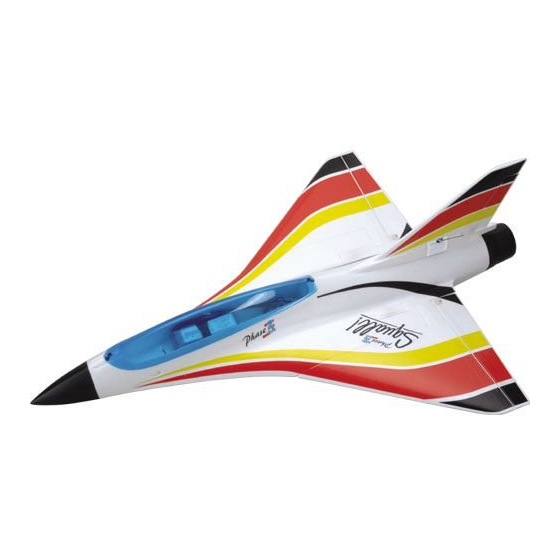
SPECIFICATIONS AND FEATURES
650mm (25.6")
885mm (34.8")
Squall! 600~650g (21.2~22.9oz)
Squall! HP 650~780g (22.9~27.5oz)
45,000~50,000
Squall! - 3800KV (11.1v) Brushless
Squall! HP - 3400KV (14.8v) Brushless
Squall! - 40A (11.1v) Brushless
Squall! HP - 45A HP (14.8v) Brushless
4 channel with elevon mixing and three
9~10g micro servos
Squall! - 3 cell 2500mAh 20C Li-Po
Squall! HP - 4 cell 2500mAh 20C Li-Po
Squall! EDF ARTF
Squall! HP EDF ARTF - Product Number PH020
- Product Number PH019
Advertisement

Related Manuals for Phase 3 Squall EDF


Summary of Contents for Phase 3 Squall EDF
- Page 1 IMPORTANT Before beginning assembly, please read and understand the warnings listed on the next page. Failure to read and understand these warnings could lead to bodily harm and/or injury. The Phase 3 Models Squall EDF, is not intended for those under 14 years of age, unless closely supervised by an adult.
-
Page 2: General Warnings
3 cell Li-Po batteries and Squall! HP is for 4 cell 3 cell Li-Po batteries and Squall! HP is for 4 cell on this and other exciting Phase 3 Models! on this and other exciting Phase 3 Models! on this and other exciting Phase 3 Models! - Page 3 SQUALL - KIT CONTENTS Decal Sheet Fuselage Bottom Intake Lip Exhaust Cone Canopy Fuselage Top Nose Cone Ducted Fan Servo Covers Hardware Pack Wing Panels Brushless ESC ITEMS REQUIRED TO COMPLETE THE SQUALL 3 x 300mm Servo Extension Leads LiPo Battery 3 x Micro Servos Squall! - 3S 2500mAh 20C or 9 - 10g...
- Page 4 ASSEMBLING THE SQUALL EDF Step 1 Mix up a quantity of rapid epoxy and apply to the wing root ensuring that it is thoroughly coated. Step 2 Push the wing panel firmly against the mating surfaces of the fuselage ensuring that it is correctly aligned.
- Page 5 Step 6 Prepare your elevon servos by connecting a pair of 300mm extension leads. Step 7 Test fit the servo in its moulded cut-out, then apply a smear of epoxy to the servo. Step 8 Push the servo into position ensuring that the lead exits in its moulded slot and the output horn is to the rear.
- Page 6 Step 11 To ensure adequate battery cooling, we recommend opening up an air exit from the battery bay into the duct. Step 12 Using a large round file or Permagrit tool as shown here, continue to open up the air exit.
- Page 7 Step 16 Use a couple of strips of masking tape to retain the elevon servo leads in their respective slots. Step 17 Prior to fitting the control horns, trim away the clear hinging tape from the slots in the elevon. Step 18 Locate a control horn and insert from the top side of elevon.
- Page 8 Step 21 Squeeze the two parts together until the bottom of the horn is flush with the underside of the elevon. Step 22 Locate a control horn self tapping screw and install through the top of the horn and into the retaining plate. Step 23 Do not over tighten the retaining screw - you do not want to crush the elevon.
- Page 9 Step 26 Ensuring the servo and elevon are centred, fit the clevis in its horn and mark the position the pushrod crosses the outer hole in the servo horn. Step 27 Form a z-bend at the marked point and cut off the excess pushrod wire as shown.
- Page 10 Step 31 Prepare the ESC by soldering on your choice of connectors. We recommend 4mm gold bullet connectors. Ensure the polarity is correct. Step 32 Test fit the fan unit, noting the wires fit in the moulded channel under the fin mount. Apply epoxy sparingly as you may wish to remove the fan unit at some point in the future.
- Page 11 Step 36 Glue the servo in position noting its orientation with the servo horn to the rear of the fin. Step 37 Ensure the base of the servo does not protrude below the base of the fin. Step 38 Before fitting the rudder control horn, trim away the clear hinging tape from the slot in the rudder.
- Page 12 Step 41 Prepare a rudder pushrod by screwing a clevis onto the rod until the thread is just visible through the clevis. Step 42 Centre the rudder servo and the rudder. Fit the clevis in its horn and mark the position the pushrod crosses the hole in the servo horn one in from the outermost.
- Page 13 Step 46 Mix up some epoxy and thoroughly cover the base of the fin taking care not to get epoxy on the servo or motor leads. Step 47 Pulling the rudder servo lead down into the duct, glue the fin in position ensuring that it is square and perpendicular to the wing.
- Page 14 Step 51 Feed the servo extension leads through the air exit hole and into the radio bay. Step 52 Hold all leads in place in the duct using clear tape or masking tape. Do not allow leads to remain loose in the duct as there is a risk they will be drawn into the fan.
- Page 15 Step 56 Now apply epoxy to the inside of the pre- painted, moulded intake lip as shown. Step 57 Glue the intake lip moulding in position making sure that any excess epoxy that squeezes out is wiped off. Step 58 Use small strips of masking tape to ensure the moulded intake lip is held tightly to the cowl as the epoxy cures.
- Page 16 Step 61 Apply more epoxy to the inside of the moulded nosecone. Step 62 Slide the nosecone in position. Wipe off any excess epoxy that squeezes out. Step 63 Locate the servo cover mouldings. Trim them with a sharp knife using the moulded lines as a guide.
- Page 17 Step 66 Repeat for the second elevon servo cover. Step 67 Carefully trim the rudder servo cover to clear the output horn. Now apply a smear of epoxy to the perimeter of the cover. Step 68 Glue the cover in position and hold or apply a small strip of masking tape while the epoxy cures.
- Page 18 Step 71 Once applied, carefully cut through the decal where the rudder separates from the fin. Step 72 Ensure that you don’t cut the hinge tape, run a sharp knife through the decal when the rudder hinges. Step 73 Apply the main wing decal in the same way buy only removing a corner of backing paper to start with.
- Page 19 Apply the decals to the other wing panel and fin. Now add the all-important Squall! decal. Step 78 Just the Phase 3 decals to add to each side of the fuselage and the top of the model is complete. Step 79 Turn the model over and apply the longer black strip to the front of the model.
- Page 20 Step 81 Use a sharp knife to trim the decal flush with the moulded nosecone. Step 82 Starting from the intake lip, apply the second black decal to the underside of the cowl. Step 83 Trim the rear of the decal flush with the moulded tailpipe using a sharp knife.
- Page 21 Step 86 Repeat the for the second wing panel working from from the trailing to leading edge. Step 87 The final stripe is applied in the same way with the backing paper removed carefully as you work your way to the leading edge.
- Page 22 Step 91 Connect the two elevons, rudder and ESC’s throttle lead to the appropriate receiver channel outputs and tidy the wiring with cable ties. Step 92 Prepare the Li-Po battery mount by removing the backing paper from the Velcro (hook and loop) supplied. Step 93 Attach it to the balsa battery mount, pressing it firmly in position.
- Page 23 Step 96 Ensure that the Velcro retaining strap is orientated as shown as it is glued into the model with the tray in this position. Step 97 Place the battery on its tray into the radio bay.Temporarily fit the canopy and test the balance point as shown below.
- Page 24 Step 98 Now remove the canopy and carefully mark the position of the tray. Step 99 Use plenty of epoxy to attach the battery tray to the base of the fuselage in this position in the radio bay. Step 100 Hold the battery in position while the epoxy cures.
-
Page 25: Control Throws
Step 103 Step 103 Step 103 Step 103 The Squall! is complete. Now set-up the The Squall! is complete. Now set-up the control throws as shown below. control throws as shown below. CONTROL THROWS All control throws are measured at the control surfaces widest point and each is measured from neutral. - Page 26 SPARE PARTS LIST PH019-01 Airframe Parts - All Squall! PH019-02 Canopy (Blue) - All Squall! PH019-03 Decal Sheet - All Squall! PH019-04 Linkage Set - All Squall! PH019-05 ESC 40A (11.1v) - Squall! PH019-06 ESC 45A HP (14.8v) - Squall! HP PH019-07 Motor 3800kv (11.1v) - Squall! PH019-08...
-
Page 27: Our Guarantee
OUR GUARANTEE Phase 3 Models guarantees this kit to be free from defects in both material and workmanship, at the date of purchase. This does not cover any component parts damaged by use, misuse or modification. in no case shall Phase 3 Model’s liability exceed the original cost of the purchased kit.
Need help?
Do you have a question about the Squall EDF and is the answer not in the manual?
Questions and answers