Table of Contents
Advertisement
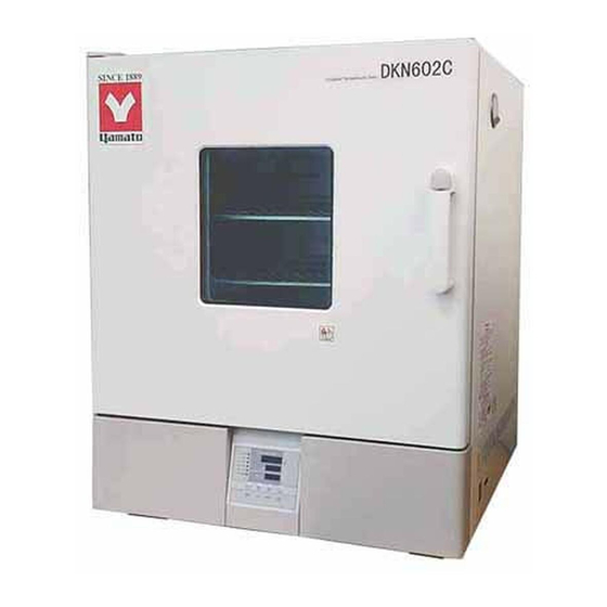
Forced Convection Oven
Models
DKN302C/402C/412C
DKN602C/612C
Instruction Manual
●
Thank you for choosing DKN-C series Forced
Convection Ovens from Yamato Scientific Co., Ltd.
● For proper equipment operation, please read and become
thoroughly familiar with this instruction manual before
use. Always keep equipment documentation safe and
close at hand for convenient future reference.
Warning
: Read instruction manual warnings and
Yamato Scientific America Inc.
Santa Clara,CA
DKN812C
DKN912C
First Edition
cautions carefully and completely
before proceeding.
Printed on recycled paper
Advertisement
Table of Contents

Subscribe to Our Youtube Channel
Related Manuals for Yamato DKN302C


Summary of Contents for Yamato DKN302C
- Page 1 First Edition ● Thank you for choosing DKN-C series Forced Convection Ovens from Yamato Scientific Co., Ltd. ● For proper equipment operation, please read and become thoroughly familiar with this instruction manual before use. Always keep equipment documentation safe and close at hand for convenient future reference.
-
Page 3: Table Of Contents
Reading Error Codes ........................41 Troubleshooting Guide ........................42 9. SERVICE & REPAIR ............... 43 10. SPECIFICATIONS ..............44 11. WIRING DIAGRAM ............... 46 DKN302C/402C/602C ........................46 DKN412C/612C ..........................47 DKN812C ............................48 DKN912C ............................49 12. REPLACEMENT PARTS LIST ............50... -
Page 4: Safety Precautions
1. SAFETY PRECAUTIONS Explanation of Symbols A Word Regarding Symbols Various symbols are provided throughout this text and on equipment to ensure safe operation. Failure to comprehend the operational hazards and risks associated with these symbols may lead to adverse results as explained below. -
Page 5: Symbol Glossary
1. SAFETY PRECAUTIONS Symbol Glossary WARNING Danger!: High Danger!: Danger!: Moving Danger!: General Warning Voltage Extremely Hot Parts Blast Hazard CAUTION Caution: Do Not Caution: Caution: Caution: May General Caution Heat Without Shock Hazard! Burn Hazard! Leak Water! Water! Caution: Caution: Toxic Water Only Chemicals... -
Page 6: Warnings & Cautions
1. SAFETY PRECAUTIONS Warnings & Cautions Warning NEVER operate equipment near combustible gases/fumes Do not install or operate DKN-C series unit near flammable or explosive gases/fumes. Unit is NOT fire or blast resistant. Negligent use could cause a fire or explosion. See “List of Hazardous Substances”... -
Page 7: Warnings & Cautions
1. SAFETY PRECAUTIONS Warnings & Cautions Caution Moving unit to install location Always carry unit to install location using cargo handling equipment, such as a forklift. Unit casters (DKN812C/912C only) are intended only to facilitate short-distance maneuvering at installation site. Do not roll unit over extended distances on casters. -
Page 8: Pre-Operation Procedures
Installation Precautions & Preparations Warning 1. Ground wire MUST be connected properly DKN302C/DKN402C/DKN602C models are rated for 115V AC power supply. ・ Ground wire must be connected to a proper grounding line or teminal in order to prevent electric shock. - Page 9 2. PRE-OPERATION PROCEDURES Installation Precautions & Preparations Warning 3. Install in a location free of flammables and explosives Never install near flammables or explosives of any kind. This unit is NOT fire or blast resistant. Simply switching the main circuit breaker (MCB) “ON” or “OFF” can produce a spark, which can then be relayed during operation, causing a fire or explosion when near flammable or explosive fluids, chemicals or gases/fumes.
- Page 10 2. PRE-OPERATION PROCEDURES Installation Precautions & Preparations Warning 4. Never disassemble or modify 5. Install on a level surface Never attempt to disassemble or modifiy Install unit on level and even surface. this unit. Doing so may cause equipment Failure to do so may cause abnormal malfunction, fire or electric shock.
- Page 11 Be advised that maximum operating temperature (DKN302C/402C/602C/412C/612C/812C - 260°C, DKN912C - 210°C) may not be reached under low external temperatures, if source voltage is below 115V (DKN302C/402C/602C) / 220V (DKN412C/612C/812C/912C).
- Page 12 Failure to do so may result in fire or electric shock. Contact a local dealer or Yamato sales office for information about replacing power cable if it becomes damaged.
-
Page 13: Component Names And Functions
3. COMPONENT NAMES AND FUNCTIONS Main Unit DKN302C/402C/412C/602C/612C Main Circuit Breaker (MCB) Exhaust ports Rear view DKN412C/612C Power cable... - Page 14 3. COMPONENT NAMES AND FUNCTIONS Main Unit DKN812C Main Circuit Breaker (MCB) Rear view Exhaust ports Power cable...
- Page 15 3. COMPONENT NAMES AND FUNCTIONS Main Unit DKN912C Main Circuit Breaker (MCB) Rear view Exhaust ports Power cable...
- Page 16 3. COMPONENT NAMES AND FUNCTIONS Main Unit Panel Item Description RUN/STOP Key Press to start or stop an operation. Press repeatedly to increase or decrease setting value incrementally. Up/Down Arrow Keys Press and hold to increase or decrease setting value perpetually. ENTER Key Press to finalize setting.
-
Page 17: Display Characters
3. COMPONENT NAMES AND FUNCTIONS Display Characters All characters displayed when making settings and during operation are defined as follows: Character Identifier Description Purpose Signifies constant Appears while entering settings for temperature constant temperature operation. setting mode Signifies temperature Appears while entering temperature setting mode settings. - Page 18 3. COMPONENT NAMES AND FUNCTIONS Display Characters Character Identifier Description Purpose Appears while entering offset Signifies calibration temperature values. See “Calibration offset setting mode Offset” (P.34) Appears while setting activation temperature for overheat prevention Signifies overheat device. See “Overheat Prevetion prevention setting mode Device Setup”...
-
Page 19: Operation Procedures
4. OPERATION PROCEDURES Operation Modes and Functions Operation modes for this unit are defined in the table below: Name Description Page Pressing the FIXED TEMP key brings up constant temperature setup mode. Constant Temperature The "▲▼" keys are used to set temperature. Mode Pressing the RUN/STOP key initiates or terminates operation. - Page 20 4. OPERATION PROCEDURES Operation Modes and Functions Operation functions for this unit are defined in the table below: № Name Description Page Auto This function is set to automatically activate (auto reset) overheat when chamber temperature exceeds the temperature prevention setting by 12°C.
-
Page 21: Mode & Function Flow
4. OPERATION PROCEDURES Mode & Function Flow The following chart illustrates the flow of modes and functions. -
Page 22: Overheat Prevention Device Setup
4. OPERATION PROCEDURES Overheat Prevention Device Setup This unit features an overheat prevention device (manual reset) which, has an independent temperature monitoring circuit, CPU, sensor and output circuit, but uses the same power source, display, and keys as the control panel. This is in addition to the internal automatic overheat prevention function (auto reset), built in for added measure against overheating. -
Page 23: Constant Temperature Mode
4. OPERATION PROCEDURES Constant Temperature Mode 1. Turn on the main circuit breaker (MCB) Constant temperature operation procedure Default values are displayed for about four seconds after turning on power. Initial settings will then show in respective displays. Temperature monitoring display: Shows current temperature in the chamber and other setting information. -
Page 24: Constant Temperature + Quick Auto Stop Mode
4. OPERATION PROCEDURES Constant Temperature + Quick Auto Stop Mode Quick auto stop This mode is used to specify when unit should terminate constant temperature operation. This mode is set during operation only. operation procedure 1. Set timer during constant temperature operation Confirm that unit is operating by confirming that FIXED TEMP lamp is illuminated. -
Page 25: Auto Stop Mode
4. OPERATION PROCEDURES Auto Stop Mode This mode is used to specify when unit should terminate constant Auto stop operation temperature operation. In contrast to quick auto stop mode, this procedure mode must be set before operation. 1. Set stop time ①... - Page 26 4. OPERATION PROCEDURES Auto Stop Mode To stop/terminate auto stop operation manually Operation stops automatically when timer reaches 0.00. An accompanying alarm sounds for approximately five seconds after operation terminates. Center display shows , indicating end of operation, with AUTO STOP lamps illuminated. Press the RUN/STOP key at any time during operation or after operation ends, to terminate auto stop operation mode.
- Page 27 4. OPERATION PROCEDURES Auto Start Mode This mode is used to specify an automatic start time for constant Auto start operation temperature operation. procedure 1. Set start time ① Press the TIMER key from the initial settings screen. ② Previous operation mode is displayed in center display. Press the TIMER key again and center display begins flashing.
- Page 28 4. OPERATION PROCEDURES Auto Start Mode To terminate auto start operation Operation begins automatically when timer reaches 0.00; but must be stopped manually. Auto start mode can be cancelled any time before or during operation by pressing the RUN/STOP key for about one second. Displays revert to initial settings screen.
-
Page 29: Programmed Operation
4. OPERATION PROCEDURES Programmed Operation Programmed This operation is used to run a combination of temperatures, times and modes as one operation. operation Temp Start Stop Time Program types A maximum of six program pattern types can be entered (middle column). ―... - Page 30 15 to increase from 100C to 150C) Temperature stabilization time is an added factor and not included in the table below. Be sure to conduct a test run before finalizing program pattern times. Conditions: room temperature 23C, no load (unit: minute) DKN302C DKN402C/412C DKN602C/612C DKN812C...
- Page 31 4. OPERATION PROCEDURES Building Programs ① Select mode and press the ENTER key. ・When PrG1 is selected, the top display will show ・When PrG2 is selected, the top display will show , signifying program “pattern”. For PrG2 pattern, select either "1" or "2" (signifying the 2 available patterns) using the ▲▼...
- Page 32 4. OPERATION PROCEDURES Building Programs ⑨ Press the ENTER key. , indicating timer setting for step 1, will be shown in the top display. Current timer setting will also be shown flashing in the center display. Before setting the timer, be sure to confirm temperature unit rise/fall capability.
- Page 33 4. OPERATION PROCEDURES Building Programs 6. End programmed operation An alert will sound when program ends. Top display will show "END", indicating that program has finished. Press the START/STOP key to return to initial setting screen. Timer function: Maximum setting for timer is 999 hours and 50 minutes. Timer can be set in increments of one minute, under 99 hours and 59 minutes.
-
Page 34: Pattern Repeat Function
4. OPERATION PROCEDURES Pattern Repeat Function This section illustrates how to use the repeat function (repeat a Setting program repeat program pattern) in a programmed operation. function Set program repeat The following illustration continues from ⑪ of Step 4, “Enter program,”... -
Page 35: Program Planning Worksheet
4. OPERATION PROCEDURES Program Planning Worksheet Do not write in this manual. Please make copies. Input into: PrG1 PrG2 PrG3 PAt1 PAt2 PAt3 Date Project Name Programmer Program Pattern... - Page 36 4. OPERATION PROCEDURES Program Planning Worksheet Do not write in this manual. Please make copies. PrG1 PrG2 PrG3 PAt1 PAt2 PAt3 Input into: Date Project Name Programmer Input Value Repeat Function (Point of return: Temperature (℃) Time (min.) number of times) :...
-
Page 37: Other Functions: Calibration Offset
4. OPERATION PROCEDURES Other Functions: Calibration Offset Using calibration offset Calibration offset is function which can correct for any differences discovered between actual chamber temperature (taken manually) and the temperature displayed on the control panel (taken by built-in sensor). Offset function can correct to either the positive or negative side of the entire unit temperature range. -
Page 38: Other Functions: Keypad Lock
4. OPERATION PROCEDURES Other Functions: Keypad Lock Using keypad lock This function locks all keys except the SUBMENU and START/STOP keys, so that settings cannot be unintentionally changed. Lock is set or cancelled with the SUBMENU key. ① Press the SUBMENU key. Select , indicating key lock function, using the ▲▼, and press the ENTER key. -
Page 39: Handling Precautions
5. HANDLING PRECAUTIONS Warning 1. Hazardous substances Never process explosive or flammable items. Fire or explosion causing serious injury or death may result. See “List of Hazardous Materials” on P.52. 2. Sample moisture precaution When processing excessively wet samples, remove as much of the moisture as possible beforehand to prevent condensation from collecting on, and excessive humidity from having an effect on internal electrical components, possibly causing damage, short circuit or electric shock. - Page 40 5. HANDLING PRECAUTIONS Caution 6. DO NOT process corrosive substances Potent acids may corrode unit interior, despite stainless steel construction. Solvents, such as alkalis, oils, halogens, etc, may also compromise silicon rubber door seal. Do not process corrosive substances or items containing corrosive substances. 7.
- Page 41 5. HANDLING PRECAUTIONS Caution 8. Sample distribution Supplied chamber rack capacity is 15kg each. Place items as evenly and as far apart as possible and do not exceed maximum load rating. Bunching multiple together in order to get more onto a single rack may compromise temperature accuracy. Distribute samples evenly and leave approximately 30% of rack space open for best results.
-
Page 42: Maintenance Procedures
6. MAINTENANCE PROCEDURES Inspection and Maintenance Warning ● Be sure that main circuit breaker (MCB) is OFF before daily inspection and maintenance of DKN-C series units. ● Perform inspections and maintenance when inside of chamber is at room temperature. ● Never attempt to disassemble unit.. Caution ●... -
Page 43: Extended Storage And Disposal
Dispose of or recycle this unit in a responsible and environmentally friendly manner. Yamato Scientific Co., Ltd. strongly recommends disassembling unit, as far as is possible, in order to separate parts and recycle them in contribution to preserving the global environment. -
Page 44: Error Codes
8. ERROR CODES Reading Error Codes DKN-C series units have a self-diagnostic function built into the CPU board and a separate safety device, independent of the CPU board. The table below shows possible causes and measures to take when safety device is triggered. Error Codes When an operational error or malfunction occurs, the alarm lamp on the control panel illuminates, an error code is displayed, and an alarm sounds. -
Page 45: Troubleshooting Guide
8. TROUBLESHOOTING Troubleshooting Guide Symptom Check Unit does not turn on/nothing is Whether power cable is connected securely to power terminal or displayed control panel outlet. displays when main circuit Whether a power outage is in progress. breaker (MCB) is turned “ON”. ... -
Page 46: Service & Repair
9. SERVICE & REPAIR Requests for Repair When a problem occurs, terminate operation immediately, turn off main circuit breaker (MCB) and disconnect power cable and contact original dealer of purchase for assistance. The following information is required for all repairs. ●... -
Page 47: Specifications
10. SPECIFICATIONS DKN302C DKN402C/412C DKN602C/612C DKN812C DKN912C Forced circulation System Temperature range *1 Room Temp + 10℃ ~ 260℃ R.T. + 10 ~ 210℃ Temperature control accuracy ±1℃ (Chamber center, 210℃, Damper: fully closed) ±2.5℃ ±2.5℃ (Set temp.: 210℃, Damper: full opened) Temperature distribution (Set temp.: 210℃,... - Page 48 10. SPECIFICATIONS DKN302C DKN402C/412C DKN602C/612C DKN812C DKN912C 115V AC 115V AC 220V AC 115V AC 220V AC 220V AC Power supply V±10% 50/60Hz, single phase 8.5A 12.5A 6.5A 12.5A 15.5A 5-35℃ / below 85% (to prevent internal condensation) Ext. temp/humidity range...
-
Page 49: Wiring Diagram
11. WIRING DIAGRAM DKN302C/402C/602C *1 Options ODK12 & ODK19 should be connected to TM2-3 & TM2-4 when used together. ------- indicates optional components. Wiring Diagram Symbol Glossary Symbol Component Symbol Component Main Circuit Breaker CONT Control Circuit Board Terminal Block... -
Page 50: Dkn412C/612C
11. WIRING DIAGRAM DKN412C/612C *1 Options ODK12 & ODK19 should be connected to TM2-3 & TM2-4 when used together. ------- indicates optional components. Wiring Diagram Symbol Glossary Symbol Component Symbol Component Main Circuit Breaker CONT Control Circuit Board Terminal Block Display Circuit Board Heater Temperature Sensor... -
Page 51: Dkn812C
11. WIRING DIAGRAM DKN812C *1 Options ODK12 & ODK19 should be connected to TM2-3 & TM2-4 when used together. ------- indicates optional components. Wiring Diagram Symbol Glossary Symbol Component Symbol Component Main Circuit Breaker CONT Control Circuit Board Terminal Block Display Circuit Board Heater Temperature Sensor... -
Page 52: Dkn912C
11. WIRING DIAGRAM DKN912C *1 Options ODK12 & ODK19 should be connected to TM2-3 & TM2-4 when used together. ------- indicates optional components. Wiring Diagram Symbol Glossary Symbol Component Symbol Component Main Circuit Breaker CONT Control Circuit Board Terminal Block Display Circuit Board H1, 2 Heater... -
Page 53: Replacement Parts List
Ribbon cable Toho Electric 1130000008 TRS5225 Toho Electric 2160000035 Current transformer CTL-6-S-H 2170010005 Circuit breaker QOU220 20A Schneider LT00037613 DKN302C Only Symbol Component Standard Manufacturer Part No. Heater SUS tube heater 800W Yamato Scientific LT00037614 Motor IC8422YAMC Yamato Scientific 2140000032... - Page 54 12. REPLACEMENT PARTS LIST DKN602C Only Symbol Component Standard Manufacturer Part No. Heater SUS tube heater 1.5kW Yamato Scientific LT00020599 Motor IC8422YAMC 10W C.C.W Yamato Scientific 2140000032 Relay AHE1254 100/120V Panasonic 2050000019 Power cable FJCU15A-P-3 Yamato Scientific LT00037616 Cable strain relief boot SR-7W-2...
-
Page 55: Hazardous Substances List
13. HAZARDOUS SUBSTANCES LIST Never attempt to process explosives, flammables or any items which contain explosives or flammables ①Nitroglycol, Glycerine trinitrate, Cellulose Nitrate and other explosive nitrate esters ②Trinitrobenzen, Trinitrotoluene, Picric Acid and other explosive nitro compounds ③Acetyl Hydroperoxide, Methyl Ethyl Ketone Peroxide, Benzoyl Peroxide and other organic peroxides ④Metallic Azide, including Sodium Azide, etc. - Page 56 Notice ● Instruction manual descriptions and specifications are subject to change without notice. ● Yamato Scientific Co., Ltd. will replace flawed instruction manuals (pages missing, pages out of order, etc.) upon request. Instruction Manual Forced Convection Oven...
Need help?
Do you have a question about the DKN302C and is the answer not in the manual?
Questions and answers
tôi cần mua linh kiện của là sấy là : motor IC-8422YAMB ( 10WC.C.W )