Harman Kardon AVR700 Service Manual
Hide thumbs
Also See for AVR700:
- Quick start manual (113 pages) ,
- Owner's manual (26 pages) ,
- Service manual (90 pages)
Table of Contents
Advertisement
harman/kardon
ESD WARNING......................................2
LEAKAGE TESTING...............................3
BASIC SPECIFICATIONS.......................4
FRONT PANEL CONTROLS.....................5
REAR PANEL CONNECTIONS................6
REMOTE CONTROL FUNCTIONS........ ...7
CONNECTIONS/INSTALLATION...............9
OPERATION... . ... .. .. ...... .. . .............14
REMOTE & PROCESSOR RESETS...........16
Released 2012
Discontinued XXXX
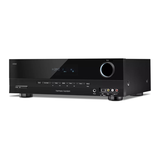
AVR700
Audio/Video Receiver
CONTENTS
TROUBLESHOOTING GUIDE..................17
PACKAGING...........................................21
UNIT EXPLODED VIEW..........................22
BLOCK DIAGRAM.................................23
PCB DRAWINGS..................................27
ELECTRICAL PARTS LIST......................38
SCHEMATICS.......................................49
WIRING DIAGRAM.................................60
harman/kardon
8500 Balboa Blvd.
Northridge, CA. 91329
Service Manual
Rev0 10/2012
Advertisement
Table of Contents

Related Manuals for Harman Kardon AVR700


Summary of Contents for Harman Kardon AVR700
-
Page 1: Table Of Contents
Service Manual AVR700 Audio/Video Receiver CONTENTS ESD WARNING…………………..……….2 TROUBLESHOOTING GUIDE…..…..…17 LEAKAGE TESTING……………….…..…..3 PACKAGING….…...……….………...………..21 BASIC SPECIFICATIONS…………………..4 UNIT EXPLODED VIEW…………..…….…..22 FRONT PANEL CONTROLS………..…..…..5 BLOCK DIAGRAM………………….………..23 REAR PANEL CONNECTIONS………….…6 PCB DRAWINGS…………………….………27 REMOTE CONTROL FUNCTIONS…….. …7 ELECTRICAL PARTS LIST……..…….….…38 CONNECTIONS/INSTALLATION………..9 SCHEMATICS………………………..…….…49 OPERATION… . … ..…… ..……14 WIRING DIAGRAM………………..….……...60... -
Page 2: Esd Warning
AVR700 harman/kardon Some semiconductor (solid state) devices can be damaged easily by static electricity. Such components commonly are called Electrostatically Sensitive (ES) Devices. Examples of typical ES devices are integrated circuits and some field effect transistors and semiconductor "chip" components. -
Page 3: Leakage Testing
AVR700 harman/kardon SAFETY PRECAUTIONS The following check should be performed for the continued protection of the customer and service technician. LEAKAGE CURRENT CHECK Measure leakage current to a known earth ground (water pipe, conduit, etc.) by connecting a leakage current tester... -
Page 4: Basic Specifications
AVR700 harman/kardon Specifications Audio Section Video Section Multichannel power: 75W per channel, two Television format: NTSC (AVR 700); channels driven @ 6 PAL (AVR 70/AVR 70C) ohms, 20Hz – 20kHz, Input level/impedance: 1Vp-p/75 ohms <0.1% THD; 100W per channel, two... -
Page 5: Front Panel Controls
If a short circuit is not found, bring the unit to an authorized Harman Kardon service center for inspection and repair before using Power On/Standby button: Press this button to turn the AVR on and put it into the it again. -
Page 6: Rear Panel Connections
AVR700 harman/kardon Rear-Panel Connectors Digital Audio HDMI ® Composite Video AC Input Connectors Connectors Connectors Connector Radio Antenna Analog Audio Subwoofer Speaker Connectors Connectors Connector Connectors Radio Antenna connectors: Connect the included AM and FM antennas to their Subwoofer connector: Connect this jack to a powered subwoofer that has a line-level respective terminals for radio reception. -
Page 7: Remote Control Functions
AVR700 harman/kardon Remote Control Functions IR Transmitter Lens Mute Button Power On Button Power Off Button AVR Button Source Selector Buttons Stereo Mode Button Tone Controls Button Surround Mode Select Buttons Volume Up/Down Buttons Display Mode Button Test Tone Sequence Button... - Page 8 Optical Digital 1, Optical Digital 2, Coaxial Digital, In addition to controlling the AVR, the AVR remote can also control a Harman Kardon Blu- HDMI (for HDMI 1 – HDMI 3 only) and Analog. This button does not function for the AM/ ray Disc ®...
-
Page 9: Connections/Installation
AVR700 harman/kardon Making Connections Connect Your TV or Video Display HDMI Monitor Out connector If your TV has an HDMI connector and you have HDMI or component video source CAUTION: Before making any connections to the AVR, ensure that the AVR’s AC devices, use an HDMI cable (not included) to connect your TV to the AVR’s HDMI Monitor... - Page 10 AVR700 harman/kardon HDMI devices Optical digital audio devices If any of your source devices have HDMI connectors, using those connectors will provide If your source devices have optical digital outputs, connect them to the AVR’s Optical the best possible video and audio performance quality. Since the HDMI cable carries Digital Audio connectors.
-
Page 11: Install The Batteries In The Remote Control
AVR700 harman/kardon Audio recorders Connect to AC Power Connect an analog audio recorder’s inputs to the AVR’s analog audio Tape Out connectors. Connect the AC power cord to the AVR’s AC Input connector and then to a working AC You can record any analog audio input signal except for the Tape 1 input. - Page 12 AVR and unplug it. Check all speaker wires for a short circuit (“+” and “–” wires touching). If none is found, bring the unit to an authorized Harman Kardon service center for inspection and repair before using it again.
- Page 13 AVR700 harman/kardon Notes on Setting Subwoofer Volume: Consult the technical specifications for your system’s main left and right speakers and locate the frequency response, usually given as a range, e.g., 80Hz – 20kHz (±3dB). Note the lowest frequency that the speakers are capable of playing (80Hz in the above the ideal setting for films is too quiet for music.
-
Page 14: Operation
AVR700 harman/kardon Operating Your AVR In the FM Stereo mode, the radio uses automatic tuning, meaning each press of the Tuning Up/Down buttons scans until a station with acceptable signal strength is found. In the FM Mono mode, the radio uses manual tuning, in which each press of a Tuning button Now that you have installed your components and completed a basic configuration, you... -
Page 15: Advanced Functions
AVR700 harman/kardon Surround Mode Selection Selecting a Surround Mode Surround-mode selection depends upon the format of the incoming audio signal as well Selecting a surround mode can be as simple or sophisticated as your individual system as your personal taste. Although there is never a time when all of the AVR’s surround and tastes. -
Page 16: Remote & Processor Resets
If the AVR does not function correctly after a processor reset, contact an authorized Harman Kardon service center for assistance. To locate an authorized service center, If you press the Sleep button after the timer has been set, the remaining play time will be visit our Web site at www.harmankardon.com. -
Page 17: Troubleshooting Guide
AVR700 harman/kardon Troubleshooting Symptom Cause Solution Unit does not function when Main Power switch is turned on power outlet Front-panel Message display lights, but there's no sound or picture No sound from any speaker Additional Setup Menu Items: Speaker On/Off, on page 15, for more information. - Page 18 AVR700 harman/kardon Check Symptom Test Point Power On Failure A) AC-Cord check. 1. FLT does not light up. B) Power Trans (Main/ST-BY) check. 2. ST-BY LED does not light up. C) Fuse's disconnection check. F300(STANDBY) D) Connector's disconnection or disjunction.
- Page 19 AVR700 harman/kardon Check Symptom Test Point 3. "CENTER" Channel dead. C) Speaker wire's disjunction. 4. "REAR" Channel dead. Close insertion of the speaker wire. D) Volume IC check. I.C No. ( 109 )(MAIN) 1. I.C voltage check ( +7.5 )V, ( -7.5 )V I.C Pin No.
- Page 20 AVR700 harman/kardon Symptom Check Test Point Stereo Effect Failure. A) FM DET COIL Inferior. Stereo does not light up. B) PLL&MPX IC check. 1. PLL&MPX I.C B+( 5 )V,B+( 3.3 )V check. 2. MPX control data check. -COM I.C & Resonator inferior.
-
Page 21: Packaging
AVR700 harman/kardon... -
Page 22: Unit Exploded View
AVR700 harman/kardon... -
Page 23: Block Diagram
AVR700 harman/kardon... - Page 24 AVR700 harman/kardon...
- Page 25 AVR700 harman/kardon...
- Page 26 AVR700 harman/kardon MAIN TRANS S1(AMP B+/B-) S2(+12V,-12V, DSP, HDMI) AC CORD S3(FLT) SUB TRANS...
-
Page 27: Pcb Drawings
AVR700 harman/kardon... - Page 28 AVR700 harman/kardon...
- Page 29 AVR700 harman/kardon...
- Page 30 AVR700 harman/kardon...
- Page 31 AVR700 harman/kardon...
- Page 32 AVR700 harman/kardon...
- Page 33 AVR700 harman/kardon...
- Page 34 AVR700...
- Page 35 AVR700 harman/kardon...
- Page 36 AVR700 harman/kardon...
- Page 37 AVR700...
-
Page 38: Electrical Parts List
AVR700 harman/kardon AMP PCB (7025-HK112-101-2) REF NO. PART NO. DESCRIPTION Inductors L201C/FL/FR/SL/SR D3 3 0-9 0000-13 3 -0 S COI L, FI LT ER- I NDUCT O SP- 25 07 1. 0 PI 2UEW T URNS 7 T SPRI NG COI L... - Page 39 AVR700 harman/kardon C212/C213 D040-10008-310-0S C,ELECT GE 85C 10UF-M/16V,5*11-5RE.SHL SY C356/C357 D006-10459-705-0S C,CERAMIC SEMI DISC F0.1UF-Z/50V-5RE PI6 C161C/L/R/SL/SR D020-10306-C06-0S C,FILM POLYESTER ST-0.01UF-J/100V-5RE PEFAM103J100 PEF TYPE C162C/L/R/SL/SR D020-10306-C06-0S C,FILM POLYESTER ST-0.01UF-J/100V-5RE PEFAM103J100 PEF TYPE C160C/L/R/SL/SR D020-10306-C06-0S C,FILM POLYESTER ST-0.1UF-J/100V-5RE PEFAM104J100 PEF TYPE...
- Page 40 AVR700 harman/kardon C198/C211/C215/C216 D011-10457-716-0S C,CERAMIC CHIP HIK X7R0.1UF-K/50V-1608REEL Connectors CP102 L102-52670-060-0S CN.WAFER 2.5MM 5267-06A 6P CP111 L102-52670-120-0S CN.WAFER 2.5MM 5267-12A 12P CP101 L108-35328-036-0S CN.WAFER 7.92MM 35328-0360, 7.92MM HEADER,VER,3CKT CN101/CN107 L109-01251-191-0S CN,WAFER C125Z1-19 19P BtoB HEADER(MALE) P=1.25MM CN106 L109-01251-291-0S CN.WAFER C125Z1-29 29P BtoB HEADER(MALE) P=1.25MM...
- Page 41 AVR700 harman/kardon R159SW/R164 C200-02216-M16-0S R,CHIP THICK 220-J , 1/16W R1253 C200-02226-M16-0S R,CHIP THICK 2.2K-J , 1/16W R140SW/R141SW C200-02226-M16-0S R,CHIP THICK 2.2K-J , 1/16W R151R/SR C200-02226-M16-0S R,CHIP THICK 2.2K-J , 1/16W R167 C200-02226-M16-0S R,CHIP THICK 2.2K-J , 1/16W R255/R258 C200-02236-M16-0S R,CHIP THICK...
- Page 42 AVR700 harman/kardon J207/J209/J217 L045-08400-604-0S CN,WIRE 1P 0.6/52MM J309/J311 L045-08400-604-0S CN,WIRE 1P 0.6/52MM J313-J316 L045-08400-604-0S CN,WIRE 1P 0.6/52MM J351-J355 L045-08400-604-0S CN,WIRE 1P 0.6/52MM J358/J360-J362 L045-08400-604-0S CN,WIRE 1P 0.6/52MM J401-J403 L045-08400-604-0S CN,WIRE 1P 0.6/52MM J405-J439 L045-08400-604-0S CN,WIRE 1P 0.6/52MM J442-J444 L045-08400-604-0S CN,WIRE 1P 0.6/52MM...
- Page 43 AVR700 harman/kardon F301 N751-22630-111-0S FUSE GLASS TUBE 20MM T6.3A /250V-SVBRTC(K) 218 IC300 J126-11170-004-1S IC,LINEAR-REGULATOR IL1117-3.3 SOT-223 3.3V 1A LOW DROPOUT PT301 8200-28015-040-1S POWER TRANS AVR1908 BKE3(DENON) STAND-BY 120V/60HZ 28*15 F301A/F301B G645-00005-001-0S HOLDER,FUSE CLIP PI5.2-REEL GT301 3790-04088-600-0S TERMINAL MET37-0002/TAPIG EARTH FITTING Front PCB (7025-HK112-101-3) REF NO.
- Page 44 AVR700 harman/kardon SW714/SW715 G180-00027-001-0S SW,TACT SKHV10920A,5MM/260G-REEL SW718-SW720 G180-00027-001-0S SW,TACT SKHV10920A,5MM/260G-REEL JACK701 G402-PJ619-A01-YS JACK,D6.5 PHONE (YUQIU) D6.5 SILVER LUG703 8410-19101-003-0S RING,TER WIRE 190MM/1P 61640BS(3.2PI)=B1813TOP BK1007#18 SW701 G000-12200-606-0S SW,PUSH SDDL-005-S(C-UL) LED702/LED705 K500-03300-004-0S LED,ROUND SLI-343D8UT32XK 3PI AMBER P=2.5 SW700 G180-00027-001-0S SW,TACT SKHV10920A,5MM/260G-REEL CNT PCB (7025-HK112-101-5) REF NO.
- Page 45 AVR700 harman/kardon C214/C218/C220/C226 D011-10317-710-1S C,CERAMIC CHIP HIK X7R)0.01UF-K/16V-1005REEL C227/C229/C231/C313 D011-10317-710-1S C,CERAMIC CHIP HIK X7R)0.01UF-K/16V-1005REEL C340/C343/C346 D011-10317-710-1S C,CERAMIC CHIP HIK X7R)0.01UF-K/16V-1005REEL C355/C357/C359 D011-10317-710-1S C,CERAMIC CHIP HIK X7R)0.01UF-K/16V-1005REEL C368/C369 D011-10317-710-1S C,CERAMIC CHIP HIK X7R)0.01UF-K/16V-1005REEL C104-C107 D011-10417-710-1S C,CERAMIC CHIP HIK X7R)0.1UF-K/16V-1005REEL C109/C111-C114 D011-10417-710-1S C,CERAMIC CHIP HIK X7R)0.1UF-K/16V-1005REEL...
- Page 46 AVR700 harman/kardon IC's IC120 J000-24160-017-0S IC,MEMORY-EEPROM CW24C16DR/ADR 16Kbit 1.8V TO 5.5V SOP8P IC113 J001-98646-601-0S IC,MEMORY-RAM W9864G6JH-6 1M*4BANKS*16BIT(64MB) TSOP54 IC119 J020-30302-004-0S IC,CPU MICRO PROCESS M3030RFGPFP FLASH(256K,12K)QFP100 IC108 J040-74040-027-0S IC,LOGIC 74VHCU04MTCX HEX INVERTER TSSOP14P IC115 J040-74257-004-0S IC,LOGIC 74LCX257MTC TSSOP-16P QUAD 2-INPUT MULTIPLEXER...
- Page 47 AVR700 harman/kardon R548/R549/R556 C200-01036-M11-1S R,CHIP THICK 10K-J , 1/16W R210/R219/R276/R520 C200-01046-M10-1S R,CHIP THICK 100K-J , 1/16W R309 C200-01056-M10-1S R,CHIP THICK 1M-J , 1/16W R109/R197 C200-01066-M10-1S R,CHIP THICK 10M-J , 1/16W R222 C200-01236-M10-1S R,CHIP THICK 12K-J , 1/16W R499-R503 C200-01526-M10-1S R,CHIP THICK 1.5K-J , 1/16W...
- Page 48 AVR700 harman/kardon XTAL101/XTAL104 E805-24R00-004-0S CRYSTAL CHIP 24.000MHz CL=15PF HCX-5FA/SMD5032 XTAL102 E805-24R57-608-0S CRYSTAL CHIP FCX-04(24.576MHz) CL=10PF SMD3225 RIVER...
-
Page 49: Schematics
AVR700 harman/kardon... - Page 50 AVR700 harman/kardon PREOUT_SW C164SW100P-J FROM BD106 R160SW 100K BD108 FRONT B'D BD107 Q115 R252 R251 KTC2875B CHASISS GND BD109 ZD101 10N(EB)-100V 10N(EB)-100V 10N(EB)-100V 10N(EB)-100V BD110 10N(EB)-100V R258 UDZ7.5B C161SL C161L C161R V3_R C161SR C161C C415 C251 100N-K R255 V3_L Q114...
- Page 51 AVR700 harman/kardon Q113 R651 KRA105S R613 R620 C604 10/16(3*5) R637 R130 470K C129 100N Q573 INC2001AC1 Q572 INC2001AC1 R635 R625 C608 R622 10/16(3*5) Q112 R655 KRA105S R644 FROM R643 C214 1N-K MAIN B'D C623 L121 BD121T C199 100/10 JACK106 10/16(3*5)
- Page 52 AVR700 harman/kardon...
- Page 53 AVR700 harman/kardon...
- Page 54 AVR700 harman/kardon Q101 C100 KRC104S R105 2.2/50-Z8154 XTAL100 18M432MHZ R107 OPEN C102 R540 R108 OPEN OPEN R109 C108 1/50-Z8155 L102 R112 BEAD R201 5.6K R113 C110 L103 C109 100N R114 BEAD 10/16-Z8154 R115 C111 100N C112 100N R204 R118 R491...
- Page 55 AVR700 harman/kardon L122 LBC2012T-4.7UH R208 R209 300K C172 IC108 74VHCU04 BEAD L125 C173 L124 LBC2012T-4.7UH R212 R213 R214 R215...
- Page 56 AVR700 harman/kardon R221 L129 BEAD-2012 L130 2.2UH C191 100/6.3-Z8156 L131 BD121T L132 L133 LBC2012T-4.7UH BEAD-2012 L134 INT1 R227 LBC2012T-4.7UH BOUT XTAL102 C203 TVDD 24M576 100/6.3-Z8156 DVDD R527 80.INT0 DVSS AVSS C209 61.RX2 AVDD 10N-K 60.TEST1 VREFH C211 C212 R229 VCOM...
- Page 57 AVR700 harman/kardon CP100 20010WS-05 R264 R265 C2327 - C500 FAULT 1000N-K IC111 IL1117-1.2 R552 47K R270 R553 0-2012 L137 IC2024 TPS2557 BEAD CP106 OPEN Q109 RT1N141C C246 C241 220/6.3-Z8157 IC114 220/6.3-Z8156 L141 IL1117-1.8 R295 BKP_HS101-2125 L142 0-2012 BEAD DQ15 VDDQ...
- Page 58 AVR700 harman/kardon C380 -30V +3V3 C378 Standby_on 100N KEY2 KEY3 FL_CE FL_CLK FL_DATA R548 VOL_UP VOL_DN R406 STBY_LED FL_SW R410 R413 R412 R416 OPEN P4_6 P0_5 50.P4_4 R422 OPEN R419 49.P4_5 R420 P4_7 P0_4 81.P0_7 R421 P5_0 82.P0_6 P0_3 R518...
- Page 59 T4A L/250V T4A L/250V F301 T6.3A L/250V T4AL/250V * F300 : AVR700/70/70C NOT USE INDICATES SAFETY CRITICAL COMPONENTS. TO REDUCE THE RISK OF ELECTIC SHOCK, LEAKAGE CURRENT OR RESISTANCE MEASUREMENTS SHALL BE CARRIED OUT ( EXPOSED PARTS ARE ACCEPTABLY INSULATED FROM THE SUPPLY CIRCUIT ) BEFORE THE APPLIANCE RETURNED TO THE CUSTOMER.
-
Page 60: Wiring Diagram
AVR700 harman/kardon...