Advertisement
Advertisement
Table of Contents

Subscribe to Our Youtube Channel
Related Manuals for AURATON 3021


Summary of Contents for AURATON 3021
- Page 1 3021 3021 P 3021 DS 3021 RTH ALARM RESET OWNER ’S MANU AL...
- Page 2 Thank you for purchasing the latest temperature controller based on an advanced microprocessor. AURATON 3021 / 3021 P / 3021 RTH / 3021 DS 3 independent temperature settings Day, night, anti-freeze. 9 independent temperature programs Including 6-user defined ones. Backlit LCD display Backlit LCD display to control the device in areas with poor lighting.
- Page 3 Temperature controller explained On the front of the enclosure, there are four function keys, backlit LCD display and temperature control knob with the OK button. LCD display setting knob with temperature integrated OK setting key button mode select key: selection key date/time/day of day mode week setting key...
- Page 4 Display 1. Day of week ( ) Indicates the current day of the week. – Each day has a number assigned. Temperature – In normal operating mode, the controller displays the temperature of the room it is installed in. 3. Temperature unit – Indicates temperature displayed in centigrade ( ).
- Page 5 Appears if the programmed mode is switched off. (see: "Manual control mode”) Transmission symbol ) – AURATON 3021R only Indicates ongoing communication with the RTH receiver. 11. Controller power on indicator ( Indicates the operating status. Visible when the controlled device is started.
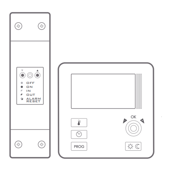
- Page 6 Description of the RTH receiver (AURATON 3021 RTH) The AURATON RTH receiver cooperates with the AURATON 3021R wireless receiver. The receiver is installed on the heating or air conditioning device and can operate under the load of 16 A. hole for fastening the receiver...
- Page 7 Legend - description of LED signalling The LED light’s green – the output device is off (the contacts COM and NC are closed). The LED light’s red – the output device is on (the contacts COM and NO are closed). The LED flashes green –...
- Page 8 Selecting proper location for temperature controller Controller location largely affects its proper operation. When located in a place without air circulation or exposed to direct sunlight, the controller may not control the temperature properly. The controller should be located on an internal wall of a building (partition wall) in a place with free air circulation.
- Page 9 Wiring your AURATON 3021 To connect the wiring, remove the enclosure as described below: Wiring terminals are located in the controller back wall, under the plastic cover. screw cover...
-
Page 10: Battery Installation/Replacement
The battery socket is located inside the controller, at the front of the enclosure. To install the batteries, remove the controller enclosure as described in the "Wiring your AURATON 3021" section. NOTE: We recommend using alkaline bateries to supply AURATON controllers. - Page 11 2x AAA 1,5 V AURATON 3021 R battery socket Place two AAA 1.5V batteries in the battery socket observing the correct polarity. ON 3021" section. AURATON 3021 DS / 3021 P Connecting an external temperature sensor. An external...
- Page 12 Replacing the enclosure 3021 CAUTION While replacing the front part of the enclosure on the back one, pay attention to the pin connector that controls the relay. Pins connector socket BACK FRONT COVER ENCLOSURE While reassembling ensure that the pins engage with the pin...
- Page 13 Fixing the controller to the wall To fix the AURATON 3021 controller to the wall: 1. Remove the enclosure (as described in the "Wiring your AURATON 3021" section). 2. Drill 2 holes diameter 6 mm in the wall (use the back of...
- Page 14 Fastening the RTH receiver NOTE ! When installing the receiver its power supply must be disconnected. It is recommended that the installation is performed by a qualified specialist. The permanent electrical system of a building must include a breaker and an overcurrent protection.
- Page 15 5. After connecting the conductors, they must be secured with the cable tie clamps and reinstall protective covers of the receiver. WARNING ! Cables supplied with the regulator are designed for conducting maximal load of 2.5 A. If devices to be connected require more power, the cables need to be replaced with cables of the appropriate cross-sectional area.
- Page 16 hole for fastening the receiver to the wall with a screw NOTE: If the wall is wooden, there is no need to use wall plugs. In such a case, drill two holes 2.7 mm in diameter instead of 5 mm, and screw the screws directly into the wood.
- Page 17 - ) on the receiver and holding it for at least 2 seconds, until the LED starts flashing green, and then releasing the button. The AURATON RTH receiver waits for pairing for 120 seconds. After that time, it automatically returns back to normal operation.
- Page 18 - ) on the receiver and holding it for at least 2 seconds, until the LED starts flashing red, and then releasing the button. The AURATON RTH receiver waits for deregistering for 120 seconds. After that time, it automatically returns back to normal operation.
- Page 19 Signalling operation and reception of data packet Each radio transmission received by the AURATON RTH receiver from the paired device is signalled by a temporary change of LED colour to orange. Switching on the relay is signalled by the LED lit red, whereas switching it off is...
- Page 20 Starting the controller for the first time After correct installation of the batteries, the LCD will display, for a second, all segments followed by the firmware version number. After a while, the controller will automatically switch to time setting mode. A blinking component on the display is in edit mode.
- Page 21 NOTE: If no key is pressed for 60 seconds in the initial edit mode, the default time 12:00 and Monday will be automatically set. NOTE: While programming any other functions, if no key is pressed for 10 seconds, this will be interpreted as pressing <OK key.
- Page 22 ( ) between 06:00 and 23:00 default temperature settings: day temperature – 21.0 °C night – 19.0 °C anti-freeze temperature – 7.0 °C temperature of the external sensor – 40.0 °C (Auraton 3021 DS only)
- Page 23 Programming day and night temperatures With AURATON 3021 2 temperatures can be programmed: Day temperature ( ) – from 5 to 30 °C Night temperature ( ) – from 5 to 30 °C Temperature of the external sensor ( ) - 10 to 55 °C...
-
Page 24: Programming Introduction
PROGRAMMING INTRODUCTION Timeline The timeline on the LCD is divided to 24 sections. Each corresponds to 1 hour of the day. Black rectangles above the timeline indicate day temperature set for the specific hours. Night temperature is set when no rectangles are present. -
Page 25: Factory Programs
Factory programs Proper program should be set for every day of the week so that the controller know when to switch between the night and day temperatures. To do so, you can use one of the factory presets available (from 0 to 2): Program –... -
Page 26: Weekly Programming
PPROGRAMMING Weekly programming To program the controller, set the day temperature intervals for individual days of the week. At other time, night temperature will be set. Sample controller setting from Monday to Sunday. Outside the intervals programmed, the night temperature will be set. Day temperature Monday 6:00 –... - Page 27 PROGRAM SELECTION To set the program: 1. Press the Prog . key. Program number segment will start blinking. 2. Press the zega key as many times as required to set the day of the week for the program. 3. Press the Prog key several times and select the program number...
- Page 28 MODIFYING USER-DEFINED PROGRAMS (prog. 3...8) To set the program: 1. Press the Prog key. Program number segment will start blinking. 2. Press the zega key as many times as required to set the day of the week for the program. 3.
-
Page 29: Manual Control
5. Press the <sun> key to select day (rectangle on) or night temperature (no rectangle). Then, select the time interval for the temperature selected with the knob. 6. By pressing the <sun key and selecting time interval the entire program is modified. 7. - Page 30 The controller will wait to set what of the two temperatures should be held (day or night). Press the sun> key or use the knob to change the setting. Press the OK.. key to acknowledge the selection. Option 2 If, for some reasons, you would like to suspend program execution, for example because of a longer party, and the controller has already started to decrease temperature for the night setting (the symbol <rę...
-
Page 31: Anti-Freeze Temperature
Anti-freeze temperature If you leave for a longer time, you can set the anti-freeze temperature. This will prevent from the consequences of freezing of water in the heating system by automatic temperature setting to 7°C. To set the anti-freeze program, select the program 0 at the desired day of week. - Page 32 The regulator will proceed to change the 3. DELAY CHANGE (AURATON 3021 / 3021 DS only) Delay is designed to prevent switching the controlled device on and off too frequently e.g. due to a momentary whiff of air caused by opening...
- Page 33 This mode is signalled by flashing text 90:SE. Turn the knob clockwise to switch the delay on and off. 90:SE – 90s delay (factory setting) 0:SE – without delay. Confirm the setting by pressing the [OK] button. The regulator will proceed to change the next parameter.
-
Page 34: Special Situations
The RTH receiver starts executing the ON - OFF cycle memorised during the last 24 hours of operation until the problem is removed. When signal return (from the AURATON 3021R regulator), the error is ź cancelled and the receiver enters its normal mode of operation. - Page 35 Additional information and notes The AURATON 3021R regulatormust be installed at least 1 metre from the ź RTH receiver (too strong a signal from the transmitters can cause interference). At least 30 seconds must elapse between switching the relay off and on.
- Page 36 The RTH receiver connection schematics control power 230 V heating device e.g. a gas furnace ALARM RESET 230V AC AURATON 3021 R...
- Page 37 Max. 230V 16 A ALARM RESET AURATON 3021 R 230V AC WARNING ! Cables supplied with the regulator are designed for conducting maximal load of 2.5 A. If devices to be connected require more power, the cables need to be replaced with cables of the appropriate cross-sectional area.
- Page 38 The AURATON 3021 regulator connection schematics control heating power device 230V AURATON 3021 e.g. a gas furnace Max. 230V electric heating device AURATON 3021 Max. 230V 16 A WARNING ! Cables supplied with the regulator are designed for conducting maximal load of 2.5 A.
- Page 39 The controller in the Dual Sensor (DS) version (with an additional temperature sensor) A controller fitted with an additional socket enables connecting an external temperature sensor (2.5 m is supplied). In order for the external sensor to be properly detected, first the sensor must be connected and then the supplied batteries must be installed in the controller.
- Page 40 The controller in the Dual Sensor version (with an additional temperature sensor) has the emergency transmitter operation function. When the voltage battery is too low (the indicator on the display), the user may decide to switch the transmitter off or to switch it on permanently.
-
Page 41: External Temperature Sensor
External temperature sensor (AURATON 3021 P) In AURATON 3021 P it is possible to connect an external temperature sensor with the 2.5m cable. In the default configuration the controller will display the temperature from the internal temperature sensor. The controller automatically switches to displaying the outside temperature when the external sensor is connected. -
Page 42: Technical Data
Additional function: Anti-freeze mode Operating cycle: Weekly Operating mode control: Maximum load current AURATON 3021 ~ 16A 250V AC of the relay contacts: Receiver RTH ~ 16A 250V AC Power supply controller: 2x AAA 1,5V alkaline battery RTH Receiver power supply:... -
Page 43: Disposal Considerations
Disposal considerations The devices are labelled with the crossed out waste bin symbol. In accordance with the European Directive 2002/96/EC and the Act on Waste electrical and electronic equipment such marking indicates that the device, after a period of use, can not be disposed of together with other household waste. - Page 44 20180423...
Need help?
Do you have a question about the 3021 and is the answer not in the manual?
Questions and answers