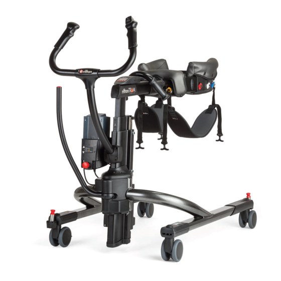
Rifton TRAM K310 Product Manual
Hide thumbs
Also See for TRAM K310:
- Product manual (24 pages) ,
- Product manual (24 pages) ,
- Product manual (32 pages)
Table of Contents
Advertisement
Quick Links
Advertisement
Table of Contents

Related Manuals for Rifton TRAM K310


Summary of Contents for Rifton TRAM K310
- Page 1 K310 & K320 Product Manual...
-
Page 2: Table Of Contents
Gait tracker Thigh straps, pelvic support, hip positioner and swivel lock 17-18 Forearm supports Arm platforms Switch pole Operation and transfers 20-22 Battery charger Troubleshooting Technical data Maintenance and cleaning Warranty, materials and user modifi cations © 2018 Rifton Equipment... -
Page 3: Safety Messages
WARNING • Thoroughly read and understand the information in this product manual before attempting to use this product. If the procedures and instructions in this product manual are not followed, serious injury or death could occur. • The TRAM may not be appropriate for all clients. The client’s therapist or physician should assess the appropriateness and safety of the TRAM for each user. - Page 4 • Using straps, trays, or supports to restrict a client’s movement is considered behavioral restraint. Rifton products are not intended for this use. • This product is intended for indoor use only and must not be used in or around water other than for bathing and shower transfers in accordance with instructions provided.
-
Page 5: Key For Users And Important Information
Use this key to determine which sections of this product manual apply to you. Technical Users For professionals who order and set up Rifton products. Home Users For care-givers who use Rifton products on a regular basis. Maintenance Personnel For anyone who is responsible for service or re-ordering of Rifton products and parts. -
Page 6: Recommended Use And User And Item Dimensions
Recommended use The TRAM is a Class 1 medical device. It is a transfer and mobility device. For transfers it enables a qualifi ed caregiver to lift a client in the seated posture and transfer the client between wheelchairs, chairs, toilets, beds or therapy tables. As a mobility device it helps a caregiver raise a client to a standing position, and then provides support for standing or ambulation. -
Page 7: Check Your Order And Basic Components
Check your order Every TRAM comes with a front handle, a battery, a battery charger, a Rifton accessories tote and a scale if ordered. All other accessories are retrofi ttable and can be added later if desired. Please check that your TRAM has been outfi tted as you ordered it. The TRAM requires some assembly before use. -
Page 8: Initial Assembly And Directions For Use
Initial assembly instructions The front handle is removed for shipping and must be attached to the TRAM frame with four bolts: With the Allen wrench found 1. Figure 8a: in the accessory carton remove the four bolts. Hold the front handle against 2. -
Page 9: Battery Box
Battery Box To prevent inadvertent WARNING operation of the up/down switch when the TRAM is not in use, press the E-Stop button (A) to disconnect the battery. The battery box houses the Figure 9a: microprocessor and rechargeable battery which power and control the TRAM’s electric actuator. -
Page 10: Battery Box
depleted. A fully charged battery will give approximately 70 complete lift cycles. To prevent damage to the battery, charge it when the light turns yellow. The indicator light will extinguish 10 minutes after the last activation of the up/down switch. It will turn on again if the up/down switch is used or if a battery is inserted into the battery box. -
Page 11: Base Frame Expansion
Base frame expansion system To avoid injury, ensure WARNING that all hands and feet are clear of the expansion handle and the base legs before expanding or retracting the base. The base frame expansion Figure 11a: system adjusts the width of the base frame from 27½”–... -
Page 12: Body Support System
Body support system To avoid injury, never WARNING operate the TRAM without the back belt in place. Always ensure that both release tabs on all buckles are fully latched before initiating a lift or transfer. Figure 12a The TRAM’s body support Figure 12a: system includes the body support pads, patient hand grips, ring clips, and the back... -
Page 13: Accessories
Accessories Scale The scale has two purposes: it Figure 13a: can be used to measure a client’s weight, and to measure the weight a client is bearing during ambulation. To use the scale, turn on the display and Figure 13a use the lb/kg button to display either pounds or kilograms. - Page 14 10 minutes. • The scale is accurate to one percent if used correctly. • Rifton recommends that the scale be calibrated by a qualifi ed technician at three to fi ve year intervals, depending on frequency of use. For instructions on service and calibration, please contact Rifton customer service.
-
Page 15: Gait Tracker
Gait Tracker The Gait Tracker app allows Figure 15a: data from the TRAM scale to be displayed on mobile phones and tablets via a Bluetooth connection. The app has two primary functions. 1. It displays the weight measured by the scale, averaged over a 10 second interval for smoothness. - Page 16 Thigh straps Thigh straps are used to make Figure 16a: seated transfers. Choose either narrow (5”) or wide (7”), depending on the needs of your client. Additional straps can be purchased for individual clients. Figure 16a Pelvic support The pelvic support is used Figure 16b: for sit-to-stand transfers and supported ambulation.
-
Page 17: Forearm Supports
Forearm supports Forearm supports give extra Figure 17a: lifting support and provide positioning support during ambulation for clients who have low muscle tone. Forearm supports adjust in many directions and angles to accommodate different positioning requirements. If forearm supports were purchased initially Figure 17a with the TRAM they will be attached and ready for use. - Page 18 Adjustments Figure 18a: Height adjustment Press button (A) and slide the post to the desired height. Loosen knob (B) to: • Slide the arm pad toward or away from the user. • Rotate up or down. Figure 18a • Rotate in or out. •...
-
Page 19: Arm Platforms
Arm platforms Attaching/detaching see pp 17 – 18. Adjustments Height adjustment: Press button (A) and slide the Figure 19a: post to the desired height. Figure 19b: Figure 19a Loosen knob (B) to: 1. Tilt for forward or backward slant. 2. Rotate horizontally. 3. -
Page 20: Switch Pole
Switch pole To prevent serious WARNING injury, a qualifi ed caregiver must determine whether it is safe to place the up/down switch within reach of the client. Do not use the switch pole with clients of unreliable judgment. The switch pole is designed to place the up/ down switch within reach of the client in Figure 20a the TRAM, enabling either the client or the... - Page 21 Using thigh straps for a seated transfer: 1. Clip one end of each thigh strap onto the yellow clips at the front of the TRAM's body support system. With the client sitting up, Figure 21a: arms raised slightly, position the body Figure 21a support system pads around the client’s rib cage a few inches below the armpits.
- Page 22 Using pelvic support for sit-to-stand or walking: Position the pelvic support 1. Figure 22a: under the client, either by lifting the client using the fi rst four steps on page 21, or by folding the saddle, shifting the client to one side and positioning Figure 22a the saddle under the client one half at a time.
-
Page 23: Battery Charger
Battery charger To prevent shock or WARNING electrocution, do not charge batteries in a wet area. Installation 1. Remove the battery from the charger to access the mounting bracket. Attach the charger to the Figure 23a: wall near an outlet, using two screws (A). -
Page 24: Troubleshooting
Troubleshooting Scale display is blank. Lift goes up or down without pressing the switch. (The red E-Stop Make sure four new AA batteries are button will always stop all movement.) inserted correctly. Unplug the front handle or switch pole TRAM veers to the side. cord. -
Page 25: Technical Data
(front wheels have brakes) lead-acid gel-type batteries. (Replacement batteries available • Motor duty cycle: Two minutes from Rifton) continuous use followed by 18 minutes idle. • Battery charger: Wall-mounted • Turning diameter: 50" (127 cm) charger, 100 - 240 V AC, max 650 mA. -
Page 26: Maintenance And Cleaning
• Immediately remove this product from use when any condition develops that might make operation unsafe. • Do not use Rifton components or products for any purpose other than their intended use. • Replace or repair components or products that are damaged or appear to be unstable. -
Page 27: Warranty, Materials And User Modifi Cations
Warranty Statement If a Rifton product breaks or fails in service during the fi rst year, we will replace it free of charge. Materials • Steel hardware items (nuts, bolts, screws, etc.) are typically zinc or nickel plated, or stainless steel. - Page 28 Use only replacement parts supplied by Rifton Equipment. We are glad to supply replacement parts. Although Rifton makes every effort to supply correct parts and instructions for repairing or refurbishing your equipment, you are responsible to make sure that the repairs or modifi cations are correctly and safely completed.
Need help?
Do you have a question about the TRAM K310 and is the answer not in the manual?
Questions and answers