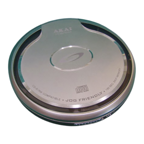
Table of Contents
Advertisement
Quick Links
COMPACT DISC COMPACT PLAYER
Performance Specifications .................................................................................................................... 2
Electrical Parts List ................................................................................................................................ 3
Wiring Diagram ....................................................................................................................................... 6
Printed Circuit Boards ............................................................................................................................. 7
Schematic Diagrams ............................................................................................................................. 13
Voltage Chart ....................................................................................................................................... 17
IC Lead Identification and Internal Diagrams ........................................................................................... 19
Block Diagram ...................................................................................................................................... 22
Exploded Drawing Parts List .................................................................................................................. 23
Exploded Drawing ................................................................................................................................. 25
Many electrical and mechanical parts in this chassis have special safety characteristics.
These safety characteristics often pass unnoticed and the protection afforded by them cannot
necessarily be obtained by using replacement components rated for higher voltage, wattage, etc.
Replacement parts that have these special safety characteristics are identified in this manual
and its supplements; electrical components having such features are identified by
schematic diagram and the parts list.
Before replacing any of these components, read the parts list in this manual carefully.
The use of substitute replacement parts that do not have the same safety characteristics as
specified in the parts list may create shock, fire or other hazards.
PD-X3780SR
CONTENTS
PRODUCT SAFETY NOTICE
Page
in the
Advertisement
Table of Contents

Summary of Contents for Akai PD-X3780SR
-
Page 1: Table Of Contents
COMPACT DISC COMPACT PLAYER PD-X3780SR CONTENTS Page Performance Specifications ........................2 Electrical Parts List ..........................3 Wiring Diagram ............................6 Printed Circuit Boards ..........................7 Schematic Diagrams ..........................13 Voltage Chart ............................17 IC Lead Identification and Internal Diagrams ................... 19 Block Diagram ............................ -
Page 2: Performance Specifications
PERFORMANCE SPECIFICATIONS GENERAL TEST CONDITION Power Supply : AC-DC Adaptor 100V: 6V DC 60H Battery: 3V (AAAx4) 120V: 6V DC 60Hz 230V: 6V DC 50Hz 110/220V: 6V Headphone Output Load : 32 ohm Reference Output : 15mW Input Signal Source : CBS SONY YED7 (PTD-001) SONY PHILIPS SBC 444A (TCD-725. -
Page 3: Electrical Parts List
ELECTRICAL PARTS LIST Ref. No. Description Mfr's Part No. Qty. CD PCB PCB 8761-01-01 195x143x0.8mm/2 (FR4) 033-008761-100 REMOTE PCB PCB WRC7-01-01 168x80x0.8mm/6 (FR4) 033-00WRC7-100 REMOTE CONTROL PORTION RESISTORS R801,802,805,806 CHIP RESISTOR 10 Kohm +-5% 1/16W (T&W) (0402/1005) 001-310356-016 R807,808 CHIP RESISTOR 100 Kohm +-5% 1/16W (0402/1005) 001-310456-016 R803 CHIP RESISTOR 1.2 Mohm +-5% 1/16W (0402/1005) - Page 4 ELECTRICAL PARTS LIST - CONTINUED Ref. No. Description Mfr's Part No. Qty. R110,111,115,301,310, CHIP RESISTOR 47 Kohm +-5% 1/16W (0402/1005) 001-347356-016 R2,106,107,108,109,615 CHIP RESISTOR 56 Kohm +-5% 1/16W (0402/1005) 001-356356-016 R116 CHIP RESISTOR 68 Kohm +-5% 1/16W (0402/1005) 001-368356-016 R122,302 CHIP RESISTOR 75 Kohm +-5% 1/16W (0402/1005) 001-375356-016 R607...
- Page 5 ELECTRICAL PARTS LIST - CONTINUED Ref. No. Description Mfr's Part No. Qty. Q601 TR PNPPWR-BUK&SC-062 2SB1132Q (ROHM) 008-A01132-000 Q101 TR PNPGEN-TAP&&U-MT3 2SA1576A (ROHM) 008-A01576-000 Q602,603 TR NPNPWR-TAP&SC-62& 2SD2150 008-A02150-000 Q604,605 TR NPNGEN-TAP&SC-70& 2SC4081 008-A04081-000 Q502 TR PNPGEN-RAD&SC-070 2SA1586GR (TOSHIBA) 008-A15860-001 (89-115-865-08C) INTEGRATED CIRCUITS IC402...
-
Page 6: Wiring Diagram
WIRING DIAGRAM TOP VIEW SLED MOTOR LIMIT SW. SPINDLE MOTOR PICK UP UNIT... -
Page 7: Printed Circuit Boards
PRINTED CIRCUIT BOARDS CD PCB 8761-01-01 TOP VIEW... - Page 8 CD PCB 8761-01-01 BOTTOM VIEW...
- Page 9 REMOTE PCB WRC7-01-01 TOP VIEW...
- Page 10 REMOTE PCB WRC7-01-01 BOTTOM VIEW...
-
Page 11: Schematic Diagrams
SCHEMATIC DIAGRAMS MVDD CD SECTION R102 C123 R105 150P(C) DVDD C121 2200P(C) IC402 IC401 64M SDRAM 16M SDRAM C103 C102 Q101 R103 C101 C137 0.01(C) 100/10V 2SA933AS 100K 100/10V 100N AVDD C104 AuVCC DQ00 DQ15 DQ00 DQ15 DQ15 DQ15 R124 100/4V DQ01 DQ14... - Page 12 REMOTE SECTION...
-
Page 13: Voltage Chart
VOLTAGE CHART THE MEASURED VALUE IS DC VOLTAGE UNIT: V CD SECTION TEST CONDITION: CD PLAY IC101 (BU9534KV) PIN'S NUMBER CD PLAY 2.51 1.30 1.30 1.27 1.32 1.32 1.27 1.27 1.92 PIN'S NUMBER CD PLAY 0.77 0.18 1.66 1.27 2.52 1.27 1.33 1.24... - Page 14 VOLTAGE CHART - CONTINUED IC301 (BH4453F) PIN'S NUMBER CD PLAY 0.88 1.34 0.93 0.93 0.93 0.88 2.51 IC501 (BU24590-8W) PIN'S NUMBER CD PLAY 1.26 1.26 1.26 1.26 1.26 1.26 1.26 1.26 PIN'S NUMBER CD PLAY 1.26 1.26 1.26 1.26 PIN'S NUMBER CD PLAY 2.52 2.52...
-
Page 15: Ic Lead Identification And Internal Diagrams
IC LEAD IDENTIFICATION AND INTERNAL DIAGRAMS IC301 BH4453F OUT2 BIAS BIAS 16.9dB 16.9dB MUTE OUT1 MUTE IC501 BU24590-8W CPU02A TEST RESET OSC1 CLOCK OSC03A PC STACK 8 PC INC RESET OSC2 612 x 4 BIT SYSTEM INSTRUCTION 16384 x 8 BIT DECODER FLAG INTERRUPT... - Page 16 IC801 SPL10A2-203A-C X32O ROSC X32I IOAB1 - 0 ROSC GEN TIME BASE (I/O) 8-BIT & RISC IOCD3 - 0 INTERRUPT PROCESSOR (I/O) LOGIC IOEF5 - 0 (INPUT) 7Kx8 12-BIT AUTO TONE 96x8 RELOAD SRAM TIMER 32 SEGMENTS x 4 COMMANDS LCD DRIVER COM3 - 0 SEG31 - 0 IC402 HY57V641620HG...
- Page 17 IC601BH6575FV PRE-DR PRE-DR CONV DC/DC VSYS CONVERTER SYSTEM MUTE1 SYSTEM RESET MUTE34 PRE-DR PRE-DR IC101 BU9534KV DVDD2 AVDD1 1bit DAC LRCK x8 Over DOUTA VBIAS Sampling DQ08 Digital Filter DQ09 DQ10 AGND1 16K SRAM DQ11 DQ12 DQ13 Digital DQ14 Servo Digital DQ15 Filter...
-
Page 18: Block Diagram
BLOCK DIAGRAM... -
Page 19: Exploded Drawing Parts List
EXPLODED DRAWING PARTS LIST Description Ref. No. Mfr's Part No. Qty. REMOTE CONTROL PORTION FRONT CAB, MOLD C.GREY 7C (ABS) CAV:1, w/SPY (w/o HOLD) 500-WRC701-xxx PLAY/PAUSE/STOP KNOB, MOLD C.GREY 7C (ABS) CAV:1, w/SPY 510-WRC703-xxx LCD COVER, STAINLESS IRON T=0.3mm 600-WRC714-000 ZEBRA CONNECTOR, 23.6x1.5x1.9mm 100-052301-190 REMOTE PCB WRC7-01-01... -
Page 20: Exploded Drawing
EXPLODED DRAWING PARTS LIST - CONTINUED Description Ref. No. Mfr's Part No. Qty. SCREW 1.7x7mm PB T.T.S. BLACK H=0.8mm (03PTTP1.7x7.0AB) 722-020173-071 7/BOTTOM CABINET TO MIDDLE CABINET CD SCREW (THOMSON), MOLDED STEEL MAT:1018 723-048761-000 SOLDER PASTE (500G/BOTTLE) (0Z63-330F-40-10) UNIT"GM" 055-300000-002... - Page 21 EXPLODED DRAWING - MAIN UNIT...
- Page 22 EXPLODED DRAWING - REMOTE CONTROL...
- Page 23 JANUARY, 2003 808-DM8761-010 Printed in Hong Kong...


Need help?
Do you have a question about the PD-X3780SR and is the answer not in the manual?
Questions and answers