Table of Contents
Advertisement
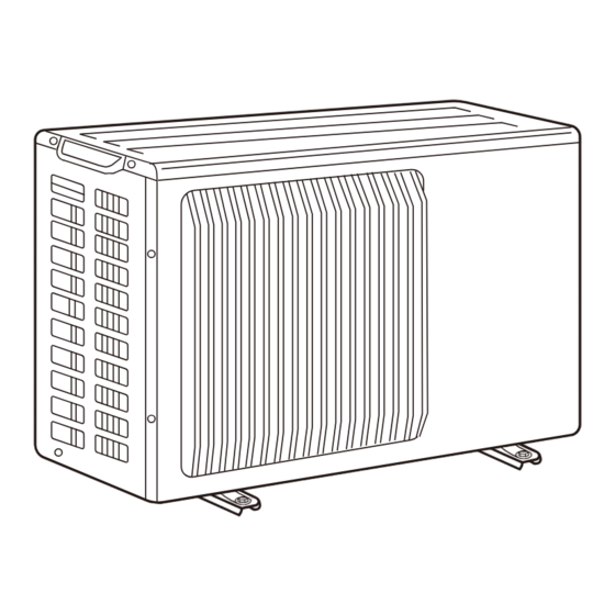
SPLIT-TYPE, AIR TO WATER HEAT PUMP
SERVICE MANUAL
R410A
Outdoor unit
[Model Name]
PUHZ-SW40VHA
PUHZ-SW50VHA
PUHZ-SW50VKA
Salt proof model
PUHZ-SW40VHA-BS
PUHZ-SW50VHA-BS
PUHZ-SW50VKA-BS
[Service Ref.]
PUHZ-SW40VHA
PUHZ-SW40VHAR1
PUHZ-SW50VHA
PUHZ-SW50VHAR1
PUHZ-SW50VKA
PUHZ-SW40VHA-BS
PUHZ-SW40VHAR1-BS
PUHZ-SW50VHA-BS
PUHZ-SW50VHAR1-BS
PUHZ-SW50VKA-BS
REVISED EDITION-C
Revision:
• Added
PUHZ-SW50VKA and
PUHZ-SW50VKA-BS in
REVISED EDITION-C.
• Some descriptions have
been modified.
• Please void OCH525
Note:
• This manual describes
service data of the outdoor
units only.
CONTENTS
TECHNICAL CHANGES ···································· 2
1. REFERENCE MANUAL ································· 3
2. SAFETY PRECAUTION ································· 4
3. FEATURES ····················································· 8
4. SPECIFICATIONS ·········································· 8
5. DATA ····························································· 10
6. OUTLINES AND DIMENSIONS ··················· 12
7. WIRING DIAGRAM ······································ 14
8. WIRING SPECIFICATIONS ·························· 16
9. REFRIGERANT SYSTEM DIAGRAM ············· 17
10. TROUBLESHOOTING ································· 19
11. DISASSEMBLY PROCEDURE ···················· 65
PARTS CATALOG (OCB525)
July 2015
No. OCH525
REVISED EDITION-B.
Advertisement
Table of Contents

Related Manuals for Mitsubishi Electric PUHZ-SW50VHA


Summary of Contents for Mitsubishi Electric PUHZ-SW50VHA
-
Page 1: Table Of Contents
SERVICE MANUAL REVISED EDITION-C R410A Outdoor unit Revision: [Model Name] [Service Ref.] • Added PUHZ-SW50VKA and PUHZ-SW40VHA PUHZ-SW40VHA PUHZ-SW50VKA-BS in REVISED EDITION-C. PUHZ-SW40VHAR1 • Some descriptions have been modified. PUHZ-SW50VHA PUHZ-SW50VHA • Please void OCH525 PUHZ-SW50VHAR1 REVISED EDITION-B. Note: PUHZ-SW50VKA PUHZ-SW50VKA • This manual describes service data of the outdoor Salt proof model units only. PUHZ-SW40VHA-BS PUHZ-SW40VHA-BS PUHZ-SW40VHAR1-BS PUHZ-SW50VHA-BS PUHZ-SW50VHA-BS... -
Page 2: Technical Changes
TECHNICAL CHANGES Service ref. have been changed as follows. PUHZ-SW40VHA PUHZ-SW40VHAR1 PUHZ-SW50VHA PUHZ-SW50VHAR1 PUHZ-SW40VHA-BS PUHZ-SW40VHAR1-BS PUHZ-SW50VHA-BS PUHZ-SW50VHAR1-BS 1. Added a new function "Energy Monitor" which allows remote controller to display power consumption and heat output. OCH525C... -
Page 3: Reference Manual
REFERENCE MANUAL INDOOR UNIT SERVICE MANUAL PUHZ-SW40VHA(-BS) PUHZ-SW50VHA(-BS) Model Name Service ref. Service manual No. EHST20C-VM6HB EHST20C-VM6HB.UK EHST20C-YM9HB EHST20C-YM9HB.UK EHST20C-TM9HB EHST20C-TM9HB.UK EHST20C-VM2/6B EHST20C-VM2/6B.UK OCH531 EHST20C-YM9B EHST20C-YM9B.UK EHST20C-VM6EB EHST20C-VM6EB.UK EHST20C-YM9EB EHST20C-YM9EB.UK EHST20C-VM6SB EHST20C-VM6SB.UK EHSC-VM2/6B EHSC-VM2/6B.UK EHSC-YM9B EHSC-YM9B.UK EHSC-TM9B EHSC-TM9B.UK OCH532 EHSC-VM6EB EHSC-VM6EB.UK EHSC-YM9EB EHSC-YM9EB.UK ERSC-VM2B ERSC-VM2B.UK... -
Page 4: Safety Precaution
SAFETY PRECAUTION 2-1. ALWAYS OBSERVE FOR SAFETY Before obtaining access to terminal, all supply circuits must be disconnected. 2-2. CAUTIONS RELATED TO NEW REFRIGERANT Cautions for units utilizing refrigerant R410A Preparation before the repair service. Precautions during the repair service. •... - Page 5 [1] Cautions for service (1) Perform service after recovering the refrigerant left in unit completely. (2) Do not release refrigerant in the air. (3) After completing service, charge the cycle with specified amount of refrigerant. (4) When performing service, install a filter drier simultaneously. Be sure to use a filter drier for new refrigerant.
- Page 6 2-3. PRECAUTIONS WHEN REUSING EXISTING R22 REFRIGERANT PIPES (1) Flowchart • Refer to the flowchart below to determine if the existing pipes can be used and if it is necessary to use a filter dryer. • If the diameter of the existing pipes is different from the specified diameter, refer to technological data materials to confirm if the pipes can be used. Measure the existing pipe thickness and check for damage. The existing pipe thickness meets specifica- The existing pipe thickness does not meet specifications or the pipes are damaged. tions and the pipes are not damaged. ▼...
- Page 7 2 Dimensions of flare cutting and flare nut The component molecules in HFC refrigerant are smaller compared to conventional refrigerants. In addition to that, R410A is a refrigerant, which has higher risk of leakage because its working pressure is higher than that of other refriger- ants. Therefore, to enhance airtightness and strength, flare cutting dimension of copper pipe for R410A has been speci- fied separately from the dimensions for other refrigerants as shown below. The dimension B of flare nut for R410A also has partly been changed to increase strength as shown below. Set copper pipe correctly referring to copper pipe flaring dimensions for R410A below. For 1/2 and 5/8 inch pipes, the dimension B changes. Use torque wrench corresponding to each dimension. Dimension A Dimension B Flare cutting dimensions Flare nut dimensions Dimension A ( (mm) Dimension B (mm) Outside Nominal Nominal Outside -0.4 diameter (mm) dimensions (in) R410A dimensions (in) diameter (mm) R410A 6.35 6.35 17.0 17.0 9.52...
-
Page 8: Features
FEATURES PUHZ-SW40VHA PUHZ-SW40VHA-BS PUHZ-SW40VHAR1 PUHZ-SW40VHAR1-BS PUHZ-SW50VHA PUHZ-SW50VHA-BS PUHZ-SW50VHAR1 PUHZ-SW50VHAR1-BS PUHZ-SW50VKA PUHZ-SW50VKA-BS CHARGELESS SYSTEM PRE-CHARGED REFRIGERANT IS SUPPLIED FOR PIPING LENGTH AT SHIPMENT maximum 10 m (PUHZ-SW40/SW50) The refrigerant circuit with LEV (Linear Expansion Valve) and power receiver always control the optimal refrigerant level regardless of the length (10 m maximum and 5 m minimum) of piping. The additional refrigerant charging work during instal- lation often causes problems. It is completely eliminated by chargeless system. This unique system improves the quality and reliability of the work done. It also helps to speed up the installation time. SPECIFICATIONS PUHZ-SW40VHA PUHZ-SW40VHAR1 PUHZ-SW40VHA-BS PUHZ-SW40VHAR1-BS PUHZ-SW50VHA PUHZ-SW50VHAR1 PUHZ-SW50VKA PUHZ-SW50VHA-BS PUHZ-SW50VHAR1-BS PUHZ-SW50VKA-BS <Reference data>... - Page 9 Cooling (A35/W7) Outside air temperature (Dry-bulb) + 35°C Outside air temperature (Wet-bulb) + 24°C Water temperature (inlet/outlet) + 12°C/+ 7°C Cooling (A35/W18) Outside air temperature (Dry-bulb) + 35°C Outside air temperature (Wet-bulb) + 24°C Water temperature (inlet/outlet) + 23°C/+ 18°C PUHZ-SW50VHA Service Ref. PUHZ-SW40VHA PUHZ-SW50VHA-BS PUHZ-SW50VKA PUHZ-SW40VHA-BS PUHZ-SW50VHAR1 PUHZ-SW50VKA-BS PUHZ-SW40VHAR1 PUHZ-SW50VHAR1-BS PUHZ-SW40VHAR1-BS Single, 50Hz, 230V Power supply (phase, cycle, voltage) Max. current External finish Munsell 3Y 7.8/1.1...
-
Page 10: Data
Initial Service Ref. charged 10 m 20 m 30 m 40 m 50 m 60 m 75 m PUHZ-SW40VHA PUHZ-SW40VHA-BS — — — PUHZ-SW40VHAR1 PUHZ-SW40VHAR1-BS PUHZ-SW50VHA PUHZ-SW50VHA-BS — — — PUHZ-SW50VHAR1 PUHZ-SW50VHAR1-BS PUHZ-SW50VKA — — — PUHZ-SW50VKA-BS Additional charge is required for pipes longer than 10 m. 5-2. COMPRESSOR TECHNICAL DATA (at 20°C) PUHZ-SW40VHA(-BS) PUHZ-SW40VHAR1(-BS) Service Ref. - Page 11 5-3. NOISE CRITERION CURVES PUHZ-SW40VHA(-BS) PUHZ-SW50VHA(-BS) SPL(dB) SPL(dB) MODE LINE MODE LINE COOLING COOLING PUHZ-SW40VHAR1(-BS) PUHZ-SW50VHAR1(-BS) HEATING HEATING NC-70 NC-70 NC-60 NC-60 NC-50 NC-50 NC-40 NC-40 NC-30 NC-30 APPROXIMATE APPROXIMATE THRESHOLD OF THRESHOLD OF HEARING FOR HEARING FOR NC-20 NC-20...
-
Page 12: Outlines And Dimensions
OUTLINES AND DIMENSIONS PUHZ-SW40VHA PUHZ-SW40VHAR1 PUHZ-SW50VHA PUHZ-SW50VHAR1 PUHZ-SW40VHA-BS PUHZ-SW40VHAR1-BS PUHZ-SW50VHA-BS PUHZ-SW50VHAR1-BS Unit: mm Installation bolt pitch 4-10×21 oval hole Rear air intake Side air intake Air discharge Service panel Terminal connections for charge plug Left・・・Power supply wiring Right・・・Indoor/Outdoor wiring Connection for liquid pipe FLARE [6.35(1/4F) - Page 13 PUHZ-SW50VKA PUHZ-SW50VKA-BS Unit: mm OCH525C...
-
Page 14: Wiring Diagram
WIRING DIAGRAM PUHZ-SW40VHA PUHZ-SW40VHAR1 PUHZ-SW50VHA PUHZ-SW50VHAR1 PUHZ-SW40VHA-BS PUHZ-SW40VHAR1-BS PUHZ-SW50VHA-BS PUHZ-SW50VHAR1-BS SYMBOL NAME SYMBOL NAME SYMBOL NAME Terminal Block <Power Supply, Indoor/Outdoor> P. B. Power Circuit Board Switch <Function Switch, Model Select> Motor for Compressor R, S Connection Terminal <L/N-Phase> Switch <Model Select>... - Page 15 PUHZ-SW50VKA PUHZ-SW50VKA-BS SYMBOL NAME SYMBOL NAME Terminal Block<Power Supply, Indoor/Outdoor> Controller Circuit Board C. B. Motor for Compressor F1, F2 Fuse<T10AL250V> Fan Motor F3, F4 Fuse<T3.15AL250V> 21S4 Solenoid Valve (4-Way Valve) CNDM Connector<Connection for Option> High Pressure Switch CN51 Connector<Connection for Option> 63HS High Pressure Sensor S.
-
Page 16: Wiring Specifications
WIRING SPECIFICATIONS FIELD ELECTRICAL WIRING (power wiring specifications) Outdoor unit model SW40, 50V ~/N (single), Outdoor unit power supply 50 Hz, 230 V Outdoor unit input capacity Main switch (Breaker) 16 A Outdoor unit power supply 3 × Min. 1.5 Indoor unit-Outdoor unit 3 × 1.5 (Polar) Indoor unit-Outdoor unit earth 1 × Min. 1.5 Remote controller-Indoor unit 2 × 0.3 (Non-polar) Outdoor unit L-N (single) 230 V AC Outdoor unit L1-N, L2-N, L3-N (3 phase) Indoor unit-Outdoor unit S1-S2 230 V AC Indoor unit-Outdoor unit S2-S3 24 V DC Remote controller-Indoor unit 12 V DC *1. A breaker with at least 3.0 mm contact separation in each poles shall be provided. Use earth leakage breaker (NV). Make sure that the current leakage breaker is one compatible with higher harmonics. Always use a current leakage breaker that is compatible with higher harmonics as this unit is equipped with an inverter. The use of inadequate breaker can cause the incorrect operation of inverter. *2. Maximum 45 m If 2.5 mm² is used, maximum 50 m. If 2.5 mm² is used and S3 is separated, maximum 80 m. -
Page 17: Refrigerant System Diagram
Refrigerant flow in heating Symbol Part name Detail COMP Compressor DC inverter twin rotary compressor (Mitsubishi Electric Corporation) H/P SW High pressure switch (63H) For protection (OFF: 4.15MPa) REV/V Reversing (4-way) valve (21S4) Change the refrigerant circuit (Heating / Cooling) and for Defrosting... - Page 18 9-1. REFRIGERANT COLLECTING (PUMP DOWN) Perform the following procedures to collect the refrigerant when moving the indoor unit or the outdoor unit. 1 S upply power (circuit breaker). • W hen power is supplied, make sure that “CENTRALLY CONTROLLED” is not displayed on the remote controller. If “CEN TRALLY CONTROLLED” is displayed, the refrigerant collecting (pump down) cannot be completed normally. • S tart-up of the indoor-outdoor communication takes about 3 minutes after the power (circuit breaker) is turned on. Start the pump-down operation 3 to 4 minutes after the power (circuit breaker) is turned ON. • I n the case of multi-units control, before powering on, disconnect the wiring between the master indoor unit and the slave indoor unit. For more details refer to the installation manual for the indoor unit. 2 A fter the liquid stop valve is closed, set the SWP switch on the control board or switch board of the outdoor unit to ON. The compressor (outdoor unit) and ventilators (indoor and outdoor units) start operating and refrigerant collecting operation begins. LED1 and LED2 on the control board or switch board of the outdoor unit are lit. • O nly set the SWP switch (push-button type) to ON if the unit is stopped. However, even if the unit is stopped and the SWP switch is set to ON less than 3 minutes after the compressor stops, the refrigerant collecting operation cannot be performed. Wait until compressor has been stopped for 3 minutes and then set the SWP switch to ON again. 3 B ecause the unit automatically stops in about 2 to 3 minutes when the refrigerant collecting operation is completed (LED1 off, LED2 lit), be sure to quickly close the gas stop valve. If LED1 is lit and LED2 is off and the outdoor unit is stopped, refriger- ant collection is not properly performed. Open the liquid stop valve completely, and then repeat step 2 after 3 minutes have passed.
-
Page 19: Troubleshooting
TROUBLESHOOTING 10-1. TROUBLESHOOTING <Check code displayed by self-diagnosis and actions to be taken for service (summary)> Present and past check codes are logged, and they can be displayed on the control board or switch board of outdoor unit. Actions to be taken for service, which depends on whether or not the trouble is reoccurring in the field, are summarized in the table below. Check the contents below before investigating details. Unit conditions at service Check code Actions to be taken for service (summary) Judge what is wrong and take a corrective action according to Displayed “10-3. SELF-DIAGNOSIS ACTION TABLE”. The trouble is reoccurring. Conduct troubleshooting and ascertain the cause of the Not displayed trouble. 1 Consider the temporary defects such as the work of protection devices in the refrigerant circuit including compressor, poor connection of wiring, noise, etc. Re- check the symptom, and check the installation environment, refrigerant amount, weather when the trouble occurred, Logged matters related to wiring, etc. 2 Reset check code logs and restart the unit after finishing service. 3 There is no abnormality in electrical component, controller The trouble is not reoccurring. board, etc. - Page 20 10-3. SELF-DIAGNOSIS ACTION TABLE <Abnormalities detected when the power is put on> Note: Refer to indoor unit section for code P and code E. Check Code Abnormal points and detection method Case Judgment and action 1 No voltage is supplied to terminal 1 Check following items. block (TB1) of outdoor unit. a) Power supply breaker is turned a) Power supply breaker off. b) Contact failure or disconnection of b) Connection of power supply terminal power supply terminal block. (TB1) c) Open phase (L or N phase) c) Connection of power supply terminal block. (TB1) 2 Electric power is not supplied to 2 Check following items. power supply terminal of outdoor power circuit board.
- Page 21 Check Code Abnormal points and detection method Case Judgment and action Miswiring of indoor/outdoor unit 1 Contact failure or miswiring of 1 Check disconnection or looseness or indoor/outdoor unit connecting polarity of indoor/outdoor unit connecting connecting wire 1. Outdoor controller circuit board can wire wire of indoor and outdoor units. automatically check the number of 2 Diameter or length of indoor/ 2 Check diameter and length of indoor/ connected indoor units. Abnormal if the outdoor unit connecting wire is out outdoor unit connecting wire. number cannot be checked automatically of specified capacity. Total wiring length: 80 m due to miswiring of indoor/outdoor unit (including wiring connecting each indoor 3 Excessive number of indoor units connecting wire, etc. after power is turned are connected to 1 outdoor unit. (4 unit and between indoor and outdoor units or more) unit) on for 4 minutes.
- Page 22 <Abnormalities detected while unit is operating> Check Code Abnormal points and detection method Case Judgment and action High pressure (High-pressure switch 63H 1 Decreased water flow 1−5 Check water circuit and repair defect. 2 Clogged filter of water pipe operated) 3 Locked water pump Abnormal if high-pressure switch 63H oper- 4 Malfunction of water pump ated ( ) during compressor operation. 5 Dirt of indoor heat exchanger *SW40,50 (63H): 4.15 MPa 6 Defective operation of stop valve 6 Check if stop valve is fully open. (Not full open) 63H: High-pressure switch 7 Clogged or broken pipe 7 Check piping and repair defect. 8 Locked outdoor fan motor 8−1 Check outdoor unit and repair defect.
- Page 23 Check Code Abnormal points and detection method Case Judgment and action 1 Disconnection or contact failure of 1 Check connection of connector (TH3,TH6/ Open/short of outdoor unit thermistors connectors TH7) on the outdoor controller circuit board. (TH3, TH6, TH7, and TH8) Abnormal if open or short is detected during Outdoor controller circuit Check connection of connector (CN3) on compressor operation. board: TH3, TH6/TH7 the outdoor power circuit board. Check Open detection of thermistors TH3 and TH6 Outdoor power circuit board: CN3 breaking of the lead wire for thermistor is inoperative for 10 seconds to 10 minutes (TH3,TH6,TH7,TH8). Refer to "10-9.TEST after compressor starting and 10 minutes POINT DIAGRAM". after and during defrosting. 2 Check resistance value of thermistor Note: Check which unit has abnormality in (TH3,TH6,TH7,TH8) or check tem- 2 Defective thermistor...
- Page 24 Check Code Abnormal points and detection method Case Judgment and action To find out the details about U9 error, turn ON SW2-1, 2-2, 2-3, 2-4, 2-5 and 2-6 when U9 error occurs. Detailed To find out the detail history (latest) about U9 error, turn ON SW2-1, 2-2 and 2-6. codes Refer to "10-10. FUNCTION OF SWITCHES, CONNECTORS AND JUMPERS". 1 A bnormal increase in power 1 C heck the field facility for the power supply. Overvoltage error 2 C orrect the wiring (U . V . W phase) to • Increase in DC bus voltage to source voltage SW40/50VHA(R1): 420 V compressor. Refer to "10-9. TEST POINT 2 D isconnection of compressor wiring SW50VKA: 400 V DIAGRAM" (Outdoor power circuit board). 3 D efective outdoor power circuit board 3 R eplace outdoor power circuit board.
- Page 25 Check Code Abnormal points and detection method Case Judgment and action 1 Defective outdoor fan (fan motor) 1 Check outdoor unit air passage. Over heat protection Abnormal if liquid thermistor (TH3) detects or short cycle of outdoor unit dur- 70: or more during compressor operation. ing cooling operation 2 Defective liquid thermistor (TH3) 23 Turn the power off and on again to check the check code. If U4 is dis- 3 Defective outdoor controller board played, follow the U4 processing direc- tion. 1 Disconnection or contact failure of 1 Check connection of connector (63HS) on Abnormal pressure of pressure sensor connector (63HS) on the outdoor the outdoor controller circuit board. (63HS) Abnormal if pressure sensor (63HS) detects controller circuit board Check breaking of the lead wire for 0.1 MPa or less.
- Page 26 Check Code Abnormal points and detection method Case Judgment and action 1 Contact failure at transmission 1 Check disconnection or looseness of Remote controller transmission error (E0)/ wire of remote controller indoor unit or transmission wire of remote signal receiving error (E4) controller. 1 Abnormal if main or sub remote controller 2 All remote controllers are set as cannot receive normally any transmission “sub” remote controller. In this 2 Set one of the remote controllers “main” if from indoor unit of refrigerant address “0” case, E0 is displayed on remote there is no problem with the action above. for 3 minutes. controller, and E4 is displayed at 3 Check wiring of remote controller. (Check code: E0) LED (LED1, LED2) on the outdoor • Total wiring length: Maximum 500 m controller circuit board.
- Page 27 Check Code Abnormal points and detection method Case Judgment and action Note: Check LED display on the outdoor 1 Contact failure, short circuit or Indoor/outdoor unit communication error miswiring (converse wiring) of controller circuit board. (Connect (Signal receiving error) indoor/outdoor unit connecting A-control service tool, PAC-SK52ST.) 1 Abnormal if indoor controller board could not receive any signal normally for 6 wire Refer to EA–EC item if LED displays minutes after turning the power on. EA–AC. 2 Defective transmitting receiving circuit of outdoor controller circuit 2 Abnormal if indoor controller board could 1 Check disconnecting or looseness of not receive any signal normally for 3 board indoor/outdoor unit connecting wire of minutes. indoor unit or outdoor unit. 3 Defective transmitting receiving circuit of indoor controller board Check all the units in case of twin/triple/ 3 Consider the unit as abnormal under...
- Page 28 Check Code Abnormal points and detection method Case Judgment and action 12 C heck operating condition of refrigerant 1 Overcharge of refrigerant Freezing/overheating protection is operat- circuit. 2 Defective refrigerant circuit (clogs) Overheating protection <Heating mode> 3 Malfunction of linear expansion valve 3 Check linear expansion valve. Abnormal if condensing temperature of 4 Reduced water flow 45 Check water piping. pressure sensor (63HS) detects · Clogged filter Tcond. °C or more and compressor · Leakage of water operation frequency is less than or equal 5 High temperature to 25 Hz. Detection is inoperative during · Over-load defrosting. · Inlet water is too warm. 6 Defective water pump 6 Check water pump. stage-a stage-s stage-b...
- Page 29 10-4. TROUBLESHOOTING ■ T hese sounds can be heard when refrigerant and/or water is (are) flowing A flowing water sound or occasional hissing sound is heard. in the indoor unit or refrigerant pipe, or when the refrigerant and/or water is (are) chugging. ■ C lean the filter of water piping. (Flow is reduced when the filter is dirty or Water does not heat or cool well. clogged.) ■ C heck the temperature adjustment and adjust the set temperature. ■ M ake sure that there is plenty of space around the outdoor unit. ■ During cooling mode, water may form and drip from the cool pipes and joints. Water or vapor is emitted from the outdoor unit.
- Page 30 10-5. TROUBLESHOOTING OF PROBLEMS Phenomena Factor Countermeasure 1. Remote controller display does 1 12 V DC is not supplied to remote controller. 1 Check LED2 on indoor controller board. not work. (Power supply display is not indicated on LCD.) (1) When LED2 is lit. Check the remote controller wiring for 2 12 to 15 V DC is supplied to remote controller, however, no display is indicated. breaking or contact failure. • “PLEASE WAIT” is not displayed. (2) When LED2 is blinking. • “PLEASE WAIT” is displayed. Check short circuit of remote controller wiring. (3) When LED2 is not lit. Refer to phenomena No.3 below. 2 Check the following. • Failure of remote controller if “PLEASE WAIT” is not displayed • Refer to phenomena No.2 below if “PLEASE WAIT” is displayed. 2. “PLEASE WAIT” display is 1 At longest 2 minutes after the power supply “PLEASE 1 Normal operation remained on the remote control- WAIT” is displayed to start up. 2 Self-diagnosis of remote controller ler. 3 “PLEASE WAIT” is displayed for 6 min- 2 Communication error between the remote controller and utes at most in case of indoor/outdoor...
- Page 31 Phenomena Factor Countermeasure 7. Remote controller display works 1 • Discharging temperature and indoor heat 1 Linear expansion valve fault normally and the unit performs O pening cannot be adjusted well due to linear expan- exchanger temperature does not rise. heating operation, however, the sion valve fault. Inspect the failure by checking discharg- capacity cannot be fully obtained. ing pressure. 2 Refrigerant shortage • Replace linear expansion valve. 3 Lack of insulation for refrigerant piping 2 • If refrigerant leaks, discharging tempera 4 Filter clogging ture rises and LEV opening increases. 5 Heat exchanger clogging Inspect leakage by checking the tem- 6 Air duct short cycle perature and opening. 7 Bypass circuit of outdoor unit fault • Check pipe connections for gas leakage. 3 Check the insulation. 4 Open intake grille and check the filter. Clean the filter by removing dirt or dust on 5 • If the filter is clogged, indoor pipe tem- perature rises and discharging pressure increases. Check if heat exchanger is clogged by inspecting discharging pres- sure. •...
- Page 32 Symptoms: “PLEASE WAIT” is kept being displayed on the remote controller. Inspection method and Diagnosis flow Cause troubleshooting Check the display time of “PLEASE WAIT” after turning on the main power. 6 minutes 2 minutes or more or less How long is “PLEASE WAIT” •...
- Page 33 LED display of the indoor controller board Symptoms: Nothing is displayed on the remote controller. 1 LED1 : LED2 : LED3 : Inspection method and Diagnosis flow Cause troubleshooting Check the voltage between S1 and S2 on the terminal block (TB4) of the indoor unit which is used to connect the indoor unit and the outdoor unit.
- Page 34 LED display of the indoor controller board Symptoms: Nothing is displayed on the remote controller. 2 LED1 : LED2 : LED3 : Inspection method and Diagnosis flow Cause troubleshooting Check the voltage between S1 and S2 on the terminal block (TB4) of the indoor unit which is used to connect the indoor unit and the outdoor unit.
- Page 35 LED display of the indoor controller board Symptoms: Nothing is displayed on the remote controller. 3 LED1 : LED2 : LED3 : — Inspection method and Diagnosis flow Cause troubleshooting Check the voltage of the terminal block (TB6) of the remote controller. 10 to 16 V DC? •...
- Page 36 10-6. HOW TO CHECK THE PARTS PUHZ-SW40VHA PUHZ-SW40VHAR1 PUHZ-SW40VHA-BS PUHZ-SW40VHAR1-BS PUHZ-SW50VHA PUHZ-SW50VHAR1 PUHZ-SW50VKA PUHZ-SW50VHA-BS PUHZ-SW50VHAR1-BS PUHZ-SW50VKA-BS Parts name Check points Thermistor (TH3) Disconnect the connector then measure the resistance with a tester. <Liquid> (At the ambient temperature 10 to 30:)
- Page 37 Check method of DC fan motor (fan motor/outdoor controller circuit board) Notes · High voltage is applied to the connecter (CNF1, 2) for the fan motor. Pay attention to the service. · Do not pull out the connector (CNF1, 2) for the motor with the power supply on. board and fan motor.) (It causes trouble of the outdoor controller circuit Self check...
- Page 38 10-8. HOW TO CHECK THE COMPONENTS <Thermistor feature chart> Low temperature thermistors • Thermistor <Liquid> (TH3) • Thermistor <2-phase pipe> (TH6) • Thermistor <Ambient> (TH7) Thermistor R0 = 15k" ± 3% B constant = 3480 ± 2% – =15exp{3480( 273+t 0: 15 k" 4.3 k" 30: 9.6 k" 3.0 k" 10: 40: 20: 6.3 k" 25: 5.2 k" −20 −10 0 10 20 30 40 50 Temperature (:) Medium temperature thermistor • Thermistor <Heat sink> (TH8)
- Page 39 Linear expansion valve (1) Operation summary of the linear expansion valve • Linear expansion valve opens/closes through stepping motor after receiving the pulse signal from the outdoor controller board. • Valve position can be changed in proportion to the number of pulse signal. <Connection between the outdoor controller board and the linear expansion valve> Outdoor controller board 12 V DC Drive circuit Blue Orange Yellow White Connector LEV-A LEV-B <Output pulse signal and the valve operation> Output Output (Phase) Opening a valve : 8 → 7 → 6 → 5 → 4 → 3 → 2 → 1 → 8 Closing a valve : 1 → 2 → 3 → 4 → 5 → 6 → 7 → 8 → 1 The output pulse shifts in above order. · When linear expansion valve operation stops, all output phases become OFF.
- Page 40 (3) How to attach and detach the coil of linear expansion valve <Composition> Linear expansion valve is separable into the main body and the coil as shown in the diagram below. Main body Coil Lead wire Stopper <How to detach the coil> Hold the lower part of the main body (shown as A) firmly so that the main body does not move and detach the coil by pulling it upward. Be sure to detach the coil holding main body firmly. Otherwise pipes can bend due to stress. <How to attach the coil> Hold the lower part of the main body (shown as A) firmly so that the main body does not move and attach the coil by inserting it downward into the main body. Then securely attach the coil stop- per to pipe B. (At this time, be careful that stress is not added to lead wire and main body is not wound by lead wire.) If the stop- per is not firmly attached to pipe B, coil may be detached from the main body and that can cause defective operation of linear expansion valve.
- Page 41 <CAUTION> TEST POINT1 is high voltage. 10-9. TEST POINT DIAGRAM Outdoor controller circuit board PUHZ-SW40VHA PUHZ-SW40VHAR1 PUHZ-SW50VHA PUHZ-SW50VHAR1 PUHZ-SW40VHA-BS PUHZ-SW40VHAR1-BS PUHZ-SW50VHA-BS PUHZ-SW50VHAR1-BS CNDM CN51 Manual defrost, 1–2: Input of low-level sound priority mode External signal output detect history record Demand control setting 1–3: Input of external contact point • Compressor operating signal reset, refrigerant • Abnormal signal address Model select Test operation Pump down Function switch Model select Pipe replace Wiring replace Transmission to out- door power circuit Connect to A control board (CN4)
- Page 42 Brief Check of POWER MODULE Usually, they are in a state of being short-circuited if they are broken. Outdoor controller circuit board Measure the resistance in the following points (connectors, etc.). If they PUHZ-SW50VKA are short-circuited, it means that they are broken. PUHZ-SW50VKA-BS 1. Check of Diode (DS1, DS2) P - L1, P - N1, N - L1, N - N1 2. Check of Q1 Note: PUHZ-SW50VKA checks solder side. P - N 3. Check of IPM P - N , P - U , P - V , P - W , N - U , N - V , N - W P-N keeps being shirt-circuited until the smoothing condenser is charged by a tester. Note: T he marks, P , N , L , L1, N1, U , V and W shown in the diagram are not actually printed on the board. <CAUTION> TEST POINT CNF11 is high voltage. Communication power supply D71 Voltage AC in (L, N) 24 V DC CNSW N L Connect to switch CNDM board 1–2: I nput of low-level sound priority mode 1–3: I nput of external contact point CN51...
- Page 43 Outdoor noise filter circuit board PUHZ-SW40VHA PUHZ-SW40VHAR1 PUHZ-SW50VHA PUHZ-SW50VHAR1 PUHZ-SW40VHA-BS PUHZ-SW40VHAR1-BS PUHZ-SW50VHA-BS PUHZ-SW50VHAR1-BS LI, NI Voltage of 230 V AC is input. Connect to the earth (Connect to the terminal block (TB1)) Connect to the earth Connect to the earth CNAC1, CNAC2 230 V AC (Connect to the outdoor control- Primary current ler circuit board (Connect to the (CNAC)) outdoor power circuit board (CN5)) LO, NO Voltage of 230 V AC is output. (Connect to the ACL) CN52C 52C relay signal (Connect to the outdoor controller circuit board...
- Page 44 Outdoor power circuit board Brief Check of DIP-IPM and DIP-PFC Usually, they are in a state of being short-circuited if they are broken. PUHZ-SW40VHA Measure the resistance in the following points (connectors, etc.). If they PUHZ-SW40VHA-BS are short-circuited, it means that they are broken. PUHZ-SW40VHAR1 1. Check of DIP-IPM P2 - U , P2 - V , P2 - W , N2 - U , N2 - V , N2 - W PUHZ-SW40VHAR1-BS 2. Check of DIP-PFC PUHZ-SW50VHA P1 - L , P1 - N , L - N1 , N - N1 PUHZ-SW50VHA-BS Note: The marks, L , N , N1 , N2 , P1 , P2 , U , V and W PUHZ-SW50VHAR1 shown in the diagram are not actually printed on the board. PUHZ-SW50VHAR1-BS R, S U, V, W Connect to the ACL Connect to the compressor (MC) 230 V AC Voltage among phases: 5 to 180 V AC LD1-LD2 DIP-PFC 280–380 V DC Connect to the outdoor controller circuit board...
- Page 45 Switch board PUHZ-SW50VKA PUHZ-SW50VKA-BS CN31 Pipe replace Emergency Wiring replace operation Pump down Demand/silent mode setting Model select A-control Test operation service kit Power failure automatic recovery/ compressor frequency setting manual defrost, delete "error history" CNSW and refrigerant address setting Connect to outdoor con- troller board OCH525C...
-
Page 46: Heating
10-10. FUNCTION OF SWITCHES, CONNECTORS AND JUMPERS The black square ( ) indicates a switch position. (1) Function of switches Action by the switch operation Type of Switch No. Function Effective timing Switch When compressor is working Manual defrost * Start Normal in heating operation. * Abnormal history clear Clear Normal OFF or operating 1 2 3 4 5 6 1 2 3 4 5 6 1 2 3 4 5 6 Refrigerant address setting... - Page 47 Special function (a) Low-level sound priority mode (Local wiring) By performing the following modification, operation noise of the outdoor unit can be reduced by about 3-4 dB. The low noise mode will be activated when a commercially available timer or the contact input of an ON/OFF switch is added to the CNDM connector (option) on the control board of the outdoor unit. • T he ability varies according to the outdoor temperature and conditions, etc. 1 C omplete the circuit as shown when using the external input adapter (PAC-SC36NA-E). (Option) 2 S W7-1 (Outdoor unit control board): OFF 3 S W1 ON: Low noise mode SW1 OFF: Normal operation X: Relay A Circuit diagram example CNDM Orange (low noise mode) D Outdoor unit control board Brown B On-site arrangement E Maximum 10 m C External input adapter F Power supply for relay (PAC-SC36NA-E) OCH525C...
- Page 48 <Display function of inspection for outdoor unit> The blinking patterns of both LED1 (green) and LED2 (red) indicate the types of abnormality when it occurs. Types of abnor- mality can be indicated in details by connecting an optional part ‘A-Control Service Tool (PAC-SK52ST)’ to connector CNM on outdoor controller board or switch board. [Display] (1)Normal condition Outdoor controller board A-Control Service Tool Unit condition LED1 (Green) LED2 (Red) Check code Indication of the display Lighted Lighted Alternately blinking display When the power is turned on Lighted Not lighted 00, etc.
- Page 49 Indication Error Outdoor controller board Check Detailed Contents Inspection method code reference LED1 (Green) LED2 (Red) page 1Check if stop valves are open. 3 blinking 1 blinking Abnormality of comp.surface thermistor(TH34) P.22 2Check if connectors (TH4, TH34, LEV-A, and LEV-B) on outdoor controller and discharging temperature (TH4) board are not disconnected.
- Page 50 <Outdoor unit operation monitor function> [When optional part ‘A-Control Service Tool (PAC-SK52ST)’ is connected to outdoor controller board or switch board (CNM)] Digital indicator LED1 displays 2 digit number or code to inform operation condition and the meaning of check code by control- ling DIP SW2 on ‘A-Control Service Tool’. Operation indicator SW2 : Indicator change of self diagnosis SW2 setting Display detail Explanation for display Unit 2 3 4 5 6 <Digital indicator LED1 working details> (Be sure that the 1 to 6 in the SW2 are set to OFF.) (1) Display when the power supply ON 1 second When the power supply ON, blinking displays by turns.
- Page 51 The black square ( ) indicates a switch position. SW2 setting Display detail Explanation for display Unit Pipe temperature/Liquid(TH3) −40 to 90 −40 to 90 (When the coil thermistor detects 0°C or below, “–” and temperature are displayed by turns.) (Example) When −10°C; 2 3 4 5 6 0.5 s 0.5 s 2 s Discharge temperature (TH4) 3 to 217 3 to 217 (When the discharge thermistor detects 100°C or more, hundreds digit, tens digit and ones digit are displayed by turns.) (Example) When 105°C; 2 3 4 5 6 0.5 s 0.5 s 2 s Output step of outdoor FAN 0 to 10 0 to 10 Step 2 3 4 5 6 The number of ON/OFF times of com- 0 to 9999 pressor...
- Page 52 The black square ( ) indicates a switch position. SW2 setting Display detail Explanation for display Unit Pipe temperature/Liquid (TH3) on error −40 to 90 occurring (When the coil thermistor detects 0°C or below, “–” −40 to 90 and temperature are displayed by turns.) (Example) When −15°C; 0.5 s 0.5 s 2 s 2 3 4 5 6 Discharge temperature (TH4) on error 3 to 217 occurring (When the temperature is 100°C or more, the 3 to 217 hundreds digit, tens digit and ones digit are displayed by turns.) (Example) When 130°C; 2 3 4 5 6 0.5 s 0.5 s 2 s Compressor operating current on error 0 to 50 occurring 0 to 50 2 3 4 5 6 Error history (1) (latest) When no error history, Alternate display of abnormal unit...
- Page 53 The black square ( ) indicates a switch position. SW2 setting Display detail Explanation for display Unit 0 to 4 The number of connected indoor units (The number of connected indoor units is displayed.) Unit 2 3 4 5 6 Capacity setting display Displayed as an outdoor capacity code. Capacity Code SW40V Code SW50V display 2 3 4 5 6 Outdoor unit setting information • The tens digit (Total display for applied setting) Setting details Display details H·P/Cooling only 0: H·P...
- Page 54 The black square ( ) indicates a switch position. SW2 setting Display detail Explanation for display Unit Indoor setting temperature 17 to 30 17 to 30 °C 2 3 4 5 6 Pressure saturation temperature (T −39 to 88 63HS −39 to 88 (When the temperature is 0°C or less, “–” and temperature are displayed by turns.) °C 2 3 4 5 6 Outdoor ambient temperature (TH7) −39 to 88 −39 to 88 (When the temperature is 0°C or less, “–” and °C temperature are displayed by turns.) 2 3 4 5 6 −40 to 200 Outdoor heat sink temperature (TH8) (When the temperature is 0°C or less, “–” and −40 to 200 temperature are displayed by turns.)
- Page 55 The black square ( ) indicates a switch position. SW2 setting Display detail Explanation for display Unit 180 to 370 DC bus voltage (When it is 100 V or more, hundreds digit, tens 180 to 370 digit and ones digit are displayed by turns.) 2 3 4 5 6 Error postponement code history (2) Postponement code display of outdoor unit Blinking: During postponement Lighting: Cancellation of postponement Code “00” is displayed in case of no postponement. display 2 3 4 5 6 Error postponement code history (3) Postponement code display of outdoor unit Blinking: During postponement Lighting: Cancellation of postponement Code “00” is displayed in case of no postponement. display 2 3 4 5 6 Error history (3) (Oldest) When no error history, “0” and “– –“ are displayed by turns.
- Page 56 The black square ( ) indicates a switch position. SW2 setting Display detail Explanation for display Unit 0 to 480 LEV-A opening pulse on error occurring (When it is 100 pulse or more, hundreds digit, tens 0 to 480 digit and ones digit are displayed by turns.) (Example) When 130 pulse; Pulse 0.5 s 0.5 s 2 s 2 3 4 5 6 Indoor room temperature (TH1) on error 8 to 39 occurring 8 to 39 2 3 4 5 6 Indoor pipe temperature/Liquid (TH2) on −39 to 88 error occurring (When the temperature is 0°C or less, “–” and −39 to 88 temperature are displayed by turns.) (Example) When –15°C; 0.5 s 0.5 s 2 s 2 3 4 5 6 Pressure saturation temperature (T −39 to 88 63HS...
- Page 57 The black square ( ) indicates a switch position. SW2 setting Display detail Explanation for display Unit 0 to 255 Discharge superheat on error occurring (When the temperature is 100°C or more, hundreds digit, tens digit and ones digit are displayed by 0 to 255 turns.) (Example) When 150°C; Cooling = TH4−T 63HS 0.5 s 0.5 s 2 s Heating = TH4−T 63HS 2 3 4 5 6 Sub cool on error occurring SC 0 to 130 0 to 130 (When the temperature is 100°C or more, hundreds digit, tens digit and ones digit are displayed by Cooling = T −TH3 turns.) 63HS Heating = T −TH2 (Example) When 115°C; 63HS 2 3 4 5 6 0.5 s 0.5 s 2 s 0 to 999 Thermo-ON time until error stops...
- Page 58 The black square ( ) indicates a switch position. SW2 setting Display detail Explanation for display Unit Comp. surface temperature (TH34) −52 to 221 (When the comp. surface thermistor detects 100°C or −52 to 221 more, hundreds digit, tens digit and ones digit are displayed by turns.) (Example) When 105°C; 0.5 s 0.5 s 2 s 2 3 4 5 6 U9 Error details (To be shown while Description Display error call is deferred.) (No error) Overvoltage error Undervoltage error 2 3 4 5 6 Input current sensor error Abnormal power synchronous signal PFC error (Overvoltage/Undervoltage/Overcurrent) PFC/IGBT error...
- Page 59 10-11. Request code list Certain indoor/outdoor combinations do not have the request code function; therefore, no request codes are displayed. Refer to indoor unit service manual for how to use the controllers and request codes for indoor unit. Description Request content Unit Remarks (Display range)
- Page 60 Description Request content Unit Remarks (Display range) Outdoor unit-Control state – Refer to 10-11-1.Detail Contents in Request Code. Compressor-Frequency control state Refer to 10-11-1.Detail Contents in Request Code. – Outdoor unit-Fan control state – Refer to 10-11-1.Detail Contents in Request Code. Actuator output state –...
- Page 61 Description Request content Unit Remarks (Display range) Error history 1 (latest) Displays error history. (" --" is displayed if no history is present.) Code Error history 2 (second to last) Displays error history. (" --" is displayed if no history is present.) Code Error history 3 (third to last) Displays error history.
- Page 62 10-11-1. Detail Contents in Request Code [Operation state] (Request code : " 0") Relay output state Power currently Data display Display Compressor 4-way valve Solenoid valve supplied to compressor – – – – Relay output state Operation mode Operation mode Display Operation mode STOP •...
- Page 63 [Actuator output state] (Request code : "54" ) Data display Actuator output state 1 Actuator output state 2 Actuator output state Actuator output state Compressor is Display Four-way valve Compressor Display warming up [Error content (U9)] (Request code : "55" ) Data display Error content 1 Error content 2...
- Page 64 [Outdoor unit – Capacity setting display] (Request code: "70") Data display Capacity [Outdoor unit – Setting information] (Request code: "71") Setting information 1 Data display Display Defrost mode Setting information 1 Standard Setting information 2 For high humidity Setting information 2 Single-/ Heat pump/ Display...
-
Page 65: Disassembly Procedure
DISASSEMBLY PROCEDURE PUHZ-SW40VHA PUHZ-SW40VHAR1 PUHZ-SW50VHA PUHZ-SW50VHAR1 PUHZ-SW40VHA-BS PUHZ-SW40VHAR1-BS PUHZ-SW50VHA-BS PUHZ-SW50VHAR1-BS OPERATING PROCEDURE PHOTOS 1. Removing the top panel, service panel, front panel and Photo 1 Top panel Top panel back panel fixing screws (1) R emove the top panel fixing screws (4 × 10), 1 from the right and 2 from the left side, and detach the top panel. Back panel (2) R emove 1 service panel fixing screw (4 × 10) and detach the service panel by pulling it downward. (See Photo 2.) Service panel (3) R emove the front panel fixing screws (4 × 10), 5 from the... - Page 66 OPERATING PROCEDURE PHOTOS 3. Removing the electrical parts box Photo 5 (1) Remove the service panel. (See Photo 2) (2) Remove the top panel. (See Photo 1) Electrical parts box Controller circuit (3) Remove the front panel. (See Photo 1) board (C.B.) (4) D isconnect the indoor/outdoor connecting wire from Terminal terminal block. block (5) D isconnect the connector CNF1, LEV-A and LEV-B on the (TB1) controller circuit board. <Symbols on the board> • CNF1 : Fan motor • LEV-A, LEV-B : LEV (6) Disconnect the pipe-side connections of the following parts. • Thermistor <Liquid>(TH3) Electrical • Thermistor <Discharge>(TH4) parts box • Thermistor <2-phase pipe, Ambient>(TH6/7) fixing • Thermistor <Comp. surface> (TH34) screws • High pressure switch (63H) • High pressure sensor (63HS) Terminal...
- Page 67 OPERATING PROCEDURE PHOTOS 5. Removing the thermistor <Ambient> (TH7) Photo 7 Thermistor <Ambient> (1) Remove the service panel. (See Photo 2) Electrical parts box (TH7) (2) Remove the top panel. (See Photo 1) (3) Remove the front panel. (See Photo 1) (4) D isconnect the connector TH7 (red) on the controller circuit board in the electrical parts box. (5) L oosen the clamp for the lead wire in the rear of the electrical parts box. (See Photo 6) (6) P ull out the thermistor <Ambient> (TH7) from the sensor holder. Note: When replacing thermistor <Ambient> (TH7), replace it together with thermistor <2-phase pipe> (TH6), since they are combined together.
- Page 68 OPERATING PROCEDURE PHOTOS 8. Removing the 4-way valve Photo 10 (1) Remove the service panel. (See Photo 2) (2) Remove the top panel. (See Photo 1) (3) Remove the front panel. (See Photo 1) (4) Remove the back panel. (See Photo 1) (5) Remove the electrical parts box. (See Photo 5) (6) Remove the 4-way valve (See Photo 9) (7) Recover refrigerant. LEV coil 4-way valve coil LEV coil (8) Remove the welded part of 4-way valve. (21S4) (LEV B) (LEV A) Note 1: Recover refrigerant without spreading it in the air. Note 2: The welded part can be removed easily by remov- ing the right side panel.
- Page 69 OPERATING PROCEDURE PHOTOS 12. Removing the compressor (MC) (1) Remove the service panel. (See Photo 2) Photo 13 Thermistor<Discharge> Thermistor (2) Remove the top panel. (See Photo 1) (TH4) <Comp. surface> (TH34) (3) Remove the front panel. (See Photo 1) Separator (4) Remove the back panel. (See Photo 1) (5) Remove the electrical parts box. (See Photo 5) (6) Remove the thermistor <Discharge> (TH4) and thermistor <Comp. surface> (TH34). (See Photo 13) (7) R emove 3 separator fixing screws (4 × 10) and remove the Compressor separator. (MC) (8) Recover refrigerant. (9) R emove 3 compressor fixing nuts by using a spanner or an adjustable wrench. (10) R emove the welded pipe of motor for compressor inlet and outlet. Separator Note: Recover refrigerant without spreading it in the air. fixing screw Compressor Valve bed...
- Page 70 PUHZ-SW50VKA PUHZ-SW50VKA-BS OPERATING PROCEDURE PHOTOS Top panel Top panel 1. Removing the top panel, service panel, front panel, back Photo 1 fixing screws fixing screw Top panel panel and grille (1) Remove the top panel fixing screws (4 × 10), one from the right and two from the left side, and detach the top panel. (2) R emove 2 service panel fixing screws (4 × 10) and detach Grille the service panel by pulling it downward. (See Photo 2) Back panel Grille fixing screws (3) R emove the front panel fixing screws (4 × 10), 3 from the front, 2 from the right and 2 from the left side, and detach the front panel. (4) R emove the back panel fixing screws (4 × 10), 5 from the Front panel right and 2 from the rear side, and detach the back panel.
- Page 71 OPERATING PROCEDURE PHOTOS 3. Removing the electrical parts box Electrical parts box (1) Remove the service panel. (See Photo 2) Photo 5 fixing screw (2) Remove the top panel. (See Photo 1) (3) Remove the front panel. (See Photo 1) Controller circuit board (C.B) Electrical part box (4) Remove the back panel. (See Photo 1) (5) D isconnect the indoor/outdoor and power supply cable connecting wire from terminal block. (6) D isconnect the connector CNF1, LEV-A and LEV-B on the controller circuit board. <Symbols on the board> • CNF1: Fan motor • LEV-A, LEV-B: LEV (7) Disconnect the pipe-side connections of the following parts. • 4-way valve (21S4) • Thermistor <Outdoor pipe> (TH3) • Thermistor <Comp. surface> (TH32) • Thermistor <Discharge> (TH4) • Thermistor <Outdoor 2-phase pipe, Outdoor> (TH6/7) • High pressure switch (63H) • High pressure sensor (63HS) (8) R emove the terminal cover and disconnect the compressor lead wire.
- Page 72 OPERATING PROCEDURE PHOTOS 5. Removing the thermistor <Ambient> (TH7) Photo 7 Thermistor <Outdoor> (1) Remove the service panel. (See Photo 2) Electrical parts box (TH7) (2) Remove the top panel. (See Photo 1) (3) D isconnect the connector TH7 (red) on the controller circuit board in the electrical parts box. (4) L oosen the clamp for the lead wire in the rear of the electrical parts box. (See Photo 6) (5) P ull out the thermistor <Ambient> (TH7) from the sensor holder. Note: When replacing thermistor <Ambient> (TH7), replace it together with thermistor <2-phase pipe> (TH6), since they are combined together.
- Page 73 OPERATING PROCEDURE PHOTOS 8. Removing the 4-way valve Photo 10 (1) Remove the service panel. (See Photo 2) (2) Remove the top panel. (See Photo 1) (3) Remove the front panel. (See Photo 1) (4) Remove the back panel. (See Photo 1) 4-way valve (5) Remove the electrical parts box. (See Photo 5) (6) Remove the 4-way valve coil. (See Photo 9) (7) Recover refrigerant. (8) Remove the welded part of 4-way valve. Note 1: Recover refrigerant without spreading it in the air. Note 2: The welded part can be removed easily by LEV coil removing the back panel.
- Page 74 OPERATING PROCEDURE PHOTOS 12. Removing the compressor (MC) Photo 12 (1) Remove the service panel. (See Photo 2) (2) Remove the top panel. (See Photo 1) (3) Remove the front panel. (See Photo 1) (4) Remove the back panel. (See Photo 1) (5) Remove the electrical parts box. (See Photo 5) Compressor (6) Remove the thermistor <Discharge> (TH4) and thermistor shell felt <Comp. surface> (TH32). (See Photo 8) (7) R emove 3 separator fixing screws (4 × 10) and remove the separator. (8) R emove the compressor body felt and compressor shell Compressor Rubber felt. (MC) mount (9) Cut the band to remove the rubber mount. (10) Recover refrigerant. (11) R emove 3 compressor fixing nuts by using a spanner or a adjustable wrench. Band (12) Remove the welded pipe of compressor inlet and outlet. Compressor body felt Note: Recover refrigerant without spreading it in the air.
- Page 75 OPERATING PROCEDURE PHOTOS 14. Removing the power receiver Photo 14 (1) Remove the service panel. (See Photo 2) (2) Remove the top panel. (See Photo 1) (3) Remove the front panel. (See Photo 1) (4) Remove the back panel. (See Photo 1) (5) Remove the electrical parts box. (See Photo 5) (6) Recover refrigerant. (7) Remove 4 welded pipes of power receiver inlet and outlet. (8) Remove 2 receiver leg fixing screws (4 × 10). (9) Remove the power receiver together with the receiver leg. Note: Recover refrigerant without spreading it in the air. Inlet Outlet Power receiver Valve bed Receiver leg fixing screw OCH525C...
- Page 76 HEAD OFFICE : TOKYO BLDG., 2-7-3, MARUNOUCHI, CHIYODA-KU, TOKYO 100-8310, JAPAN cCopyright 2012 MITSUBISHI ELECTRIC CORPORATION Distributed in Jul. 2015 No.OCH525 REVISED EDITION-C Distributed in Nov. 2014 No.OCH525 REVISED EDITION-B Distributed in May 2013 No.OCH525 REVISED EDITION-A Distributed in Oct. 2012 No.OCH525 New publication, effective Jul. 2015 Made in Japan Specifications are subject to change without notice.