Table of Contents
Advertisement
Advertisement
Table of Contents

Related Manuals for Avaya IP401


Summary of Contents for Avaya IP401
- Page 1 IP Office 2.1 Installation Manual 40DHB0002USCL Issue 10c (11 May 2004)
-
Page 3: Table Of Contents
Scope of Manual ........................2 Scope of Manual ........................3 IP401 Compact Office Platform....................5 IP401 Compact Office ..........................5 IP401 Compact Office - Front View ......................6 IP401 Compact Office - Rear View......................7 Typical Configuration..........................8 IP403 Office Platform ......................... 9 IP403 Office.............................. - Page 4 Installation of Voice Compression Modules (VCM) .................. 51 Dual Modem Module ..........................52 Rack Mounting Assembly Instructions...................... 53 IP401 Expansion and Installation of Integral Modules................54 IP401 Compact Office Wall Mounting....................... 55 Initial Assembly............................56 Basic System Programming ....................57 Introduction...............................
- Page 5 Table Of Contents Port Pinouts ............................79 Analog Trunk Ports (RJ45) ........................79 Power Fail and POT Ports (RJ45) ....................... 79 DS/DT Ports (RJ45) ..........................79 ISDN Port – BRI (RJ45) ........................80 ISDN Port – PRI (RJ45) ........................80 LAN Port –...
-
Page 7: Ip Office Installation
IP Office training courses. • Ensure that you have read and understood this manual before beginning installation. For installation instructions for the Avaya IP Office - Small Office Edition, refer to the separate Small Office Edition Installation Manual. Installation Manual Page 1 IP Office 2.1... -
Page 8: Scope Of Manual
IP Office Installation Scope of Manual This manual, for Avaya IP Office systems, covers the following subjects and should be read in the sequence shown below: • Avaya IP Office Platforms This section provides details of the various Avaya IP Office platforms available. Illustrations of the front and rear of each unit show what ports/sockets/etc are provided. -
Page 9: Scope Of Manual
Scope of Manual This manual, for Avaya IP Office systems, covers the following subjects and should be read in the sequence shown below: • Avaya IP Office Platforms This section provides details of the various Avaya IP Office platforms available. Illustrations of the front and rear of each unit show what ports/sockets/etc are provided. -
Page 11: Ip401 Compact Office Platform
The auto-negotiating 10/100 BaseT LAN hub provides access to networks and/or up to eight IP telephones. The DT ports support Avaya 2000 series telephones. DT ports are set to A-Law PCM encoding at default but can be programmed to -Law PCM encoding. -
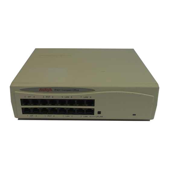
Page 12: Ip401 Compact Office - Front View
When the Uplink switch is in the in position the port can be connected directly to a PC. Cables IP401 Compact Office 2 is supplied with one red CAT5E cable. The Compact Office 4 is supplied with two red CAT5E cables. -
Page 13: Ip401 Compact Office - Rear View
• BRI Ports Two BRI trunk interface ports are fitted on an IP401 Compact Office 4 and only one on an IP401 Compact Office 2; providing four and two trunks respectively. See IP401 Expansion and Installation of Integral Modules for expansion and IP400 Office Systems for country specific variants. -
Page 14: Typical Configuration
The eight port 10/100M Hub allows the local PCs and Printers to be networked. Connectivity for all voice and data traffic between the Warehouse and the regional office is carried over the optional IP401 WAN interface using Voice over IP and standards based compression (through the optional IP400 VCM 5 media card). -
Page 15: Ip403 Office Platform
DT ports - support Avaya 2000 series telephones. • DS ports - support Avaya 6400, 2420 series and/or Avaya 4400 series telephones. Both ports can be set for either -Law or A-Law PCM encoding. At default DT ports are set to A-Law and DS ports are set to -Law. -
Page 16: Expansion Modules
IP Office Installation Expansion Modules Optional Expansion Modules allow the IP403 Office to be expanded to 100 extensions. These modules (with the exception of the WAN3) are connected via the Expansion Port sockets that are located on the back of each unit. Up to 3, in any combination, of the following Expansion Modules can be supported by the IP403 Office base unit. -
Page 17: Ip403 Office - Front View
DT ports are for connection to Avaya 2000 series telephones. • DS ports are for connection to Avaya 4400, 2420 and/or 6400 series telephones. • At default DT ports are set to A-Law PCM encoding and DS ports to either A-Law or -Law PCM encoding . -
Page 18: Ip403 Office - Rear View
IP Office Installation IP403 Office - Rear View • External O/P Socket Two relay ports that allow externally powered circuits to be controlled via a single 3.5mm stereo jack socket. • DC Power I/P Socket Socket for the external 24V DC unregulated power supply (supplied with equipment). •... -
Page 19: Typical Configuration
A customer with sophisticated telephony requirements, needing 30 exchange lines and 80 Display Terminals. This configuration provides support for 98 Avaya 20 series digital telephones (18 spare for growth) and a single Primary Rate ISDN connection. If growth beyond 18 users or additional line capacity were anticipated, the IP406 Office would be considered more appropriate. -
Page 21: Ip406 Office Platform
IP406 Office Platform IP406 Office The IP406 Office base unit supports up to 180 extensions by using up to 6 Expansion modules. Connection to trunks is via any two of the following integral interface modules as follows:- • Single PRI E1/PRI E1-R2 (30 trunks) or •... -
Page 22: Ip406 Office - Front View
IP Office Installation IP406 Office - Front View • LAN Ports The eight auto-negotiating 10/100 BaseT LAN hub ports are used for PC and server connectivity. They can also be used to connect to the optional IP400 WAN3 Expansion Module and IP telephones. -
Page 23: Ip406 Office - Rear View
IP406 Office Platform IP406 Office - Rear View • External O/P Socket Two relay ports that allow externally powered circuits to be controlled via a single 3.5mm stereo jack socket. • DC Power I/P Socket Socket for the external 24V DC unregulated power supply (supplied with kit). •... -
Page 24: Typical Configurations
IP Office Installation Typical Configurations Scenario 1 A business requiring 60 analog Telephones and 8 Basic Rate ISDN lines (16 channels). The IP406 Office BRI 16 with two IP400 Office Phone 30 modules provides the required line and extension capacity. Through the use of PhoneManager Lite the functionality provided by the Analog Telephones is greatly enhanced. - Page 25 IP406 Office Platform Scenario 2 A business requiring 180 analog Telephones and 60 lines. The configuration illustrates a fully configured IP406 Office providing 180 extensions and 60 trunks. Factory shipped with a single PRI the system is fitted with an extra trunk card in its spare slot to provide the additional 30 lines.
-
Page 27: Ip412 Office Platform
IP412 Office Platform IP412 Office The IP412 Office base unit supports up to 360 extensions by using up to12 Expansion modules. Connection to trunks is via a combination of any of the following integral interface modules :- • Single or Dual PRI E1/PRIE1-R2 (30 or 60 trunks respectively). •... -
Page 28: Ip412 Office - Front View
IP Office Installation IP412 Office - Front View • LAN Ports The segmented dual independent auto-negotiating 10/100 BaseT Ethernet ports are used for PC and server connectivity. They can also be used to connect to the optional IP400 WAN3 Expansion Module and IP telephones. Information relating to incoming and outgoing telephone calls can be forwarded to PC based applications via these ports. -
Page 29: Ip412 Office - Rear View
IP412 Office Platform IP412 Office - Rear View • External O/P Socket Two relay ports that allow externally powered circuits to be controlled via a single 3.5mm stereo jack socket. • DC Power I/P Socket Socket for the external 24V DC unregulated power supply (supplied with kit). •... -
Page 30: Scenario 1
IP412 Office PRI 48 T1 • 6 X IP400 Office Digital Station 30 Module • 2 x IP400 Office Analog Trunk 16 • 180 x Avaya 6412 Digital Terminals Installation Manual Page 24 IP Office 2.1 40DHB0002USCL Issue 10c (11th May 2004) -
Page 31: Scenario 2
IP412 Office Platform Scenario 2 A Business requiring 90 IP hardphones, 90 IP softphones and 60 lines. This configuration illustrates an IP412 Office PRI 60 E1 fitted with two optional IP400 Office Voice Compression Module 20s. These two internally fitted cards allow up 40 simultaneous calls to external parties, as they are only used when an IP extension is calling a non-IP telephone or line. -
Page 33: Expansion Modules
(1-16). • DT ports are used for connection to Avaya 2000 series telephones and support either A-Law or U-Law PCM encoding. Both DT and DS ports can be set for either U-Law or A-Law PCM encoding. Using DT Line Cords and standard structured wiring, these RJ45 ports can be extended to the required telephone location. -
Page 34: Ip400 Digital Stations 16/30
The IP400 Digital Station Expansion Module similar to the IP400 Digital Terminal Expansion Module (see IP400 Digital Terminal 16/30) with the exception that the Ports are labeled DS not DT and support Avaya 6400, 2420 or 4400 series telephones. IP400 Phone 8/16/30 •... -
Page 35: Ip400 So8
Expansion Modules IP400 So8 The So8 Module is only applicable to countries that support the ETSI signaling protocol (see Expansion Modules). • BRI Ports These are 64k ISDN BRI S-Bus ports and are used for connection to ISDN Telephones, Group 4 faxes, Video conferencing units, etc. -
Page 36: Ip400 Wan3
IP Office Installation IP400 WAN3 • LAN Port The LAN Port is the expansion port and permits connection to an IP403, IP406 or IP412 Office platform LAN Port. A LAN Interconnect cable is required for connection to an IP403 or IP406. An IP412 requires a LAN Crossover cable. -
Page 37: Ip400 Analog Trunk 16
Expansion Modules IP400 Analog Trunk 16 • Analog Trunk Ports These ports are used for connection to standard analog trunks (loop start or ground start). Using standard structured wiring, these RJ45 ports can be extended to the required trunk sockets. Trunk ports 1 and 2 are, in the event of power failure, automatically switched to PF1 and PF2 respectively on the rear of the unit. -
Page 39: Country Variants
Country Variants Overview of Country Variants The following are lists of the country variants for each IP400 Office platform, trunk module kits, Integral module kits and expansion modules. The PCS level for each module can be found on a label that is stuck to the base of each module. -
Page 40: Ip400 Office Systems
A-Law/ Country SAP Code U-Law IP401 Compact Office DT2 700184617 IP401 WAN Expansion kit 700185093 IP401 Memory Expansion kit 700198351 IP401 CO DT2 Expansion kit 700185085 IP401 Compact Office DT4 700184633 IP403 Office Variant A-Law/ Country SAP Code U-Law IP403 Office DT (No Trunks) -
Page 41: Integral Module Kits
Country Variants IP412 Office Variant A-Law/ Country SAP Code U-Law IP412 Office (No Trunks) ROW/CALA 700234479 IP412 Office PRI 30 E1 ROW but not CH, 700184724 CALA IP412 Office PRI 60 E1 ROW but not CH, 700184732 CALA IP412 Office (No Trunks) 700210784 IP412 Office PRI 24 T1 700184740... -
Page 42: Trunk Module Kits
IP Office Installation Trunk Module Kits BRI Trunk Interface Module Variant Country SAP Code IP400 BRI expansion kit 700185168 IP400 BRI 8 (UNI) expansion kit ROW but not CH 700262017 Analog Trunk Interface Module Variant Country SAP Code IP400 ANALOG 4 (LS) expansion kit NA/CALA 700185192 IP400 ANALOG 4 EU (LS) expansion kit... -
Page 43: Power Supplies
Country Variants Power Supplies Common Lump-in-Line Power Supply units are supplied with each IP Office/Expansion Module. However, the power leads are county specific and must be ordered separately. These power leads only applicable to IP Office base units/Expansions modules and must not be used on the IP Office Small Edition, see the separate Installation Manual for details. -
Page 44: Expansion Modules
IP Office Installation Expansion Modules IP400 Phone Variant Country SAP Code IP400 Phone 8 700184773 IP400 Phone 16 700184781 IP400 Phone 30 700184799 IP400 Digital Terminals Variant Country SAP Code IP400 Digital Terminal 16 700185606 IP400 Digital Terminal 30 700185069 IP400 Digital Stations Variant Country... -
Page 45: Preparing For Installation
Preparing for Installation Preparing for Installation This section reviews the requirements for installing an IP Office system. You must meet these requirements for the system to operate safely and in the intended manner. This section covers : • Tools & Parts Required. -
Page 46: Space Requirements
• Height : • A IP401 Compact Office module is 71mm (2.8 inches) high. • IP403, 406, 412 and all Expansion modules are 71mm(2.8 inches) high. Hence the total height of a system is the number of modules multiplied by 71mm (2.8 inches). -
Page 47: Environmental Requirements
Preparing for Installation Environmental requirements The planned location must meet the following requirements: • Check that the area is a well ventilated area, having a temperature range of 0°C to +40°C and a humidity range of 10% to 95% non-condensing. •... -
Page 48: Power Supply Requirements
• UPS Equipment The use of UPS's to support the IP Office system during mains power failure is highly recommended. Such equipment also provides mains conditioning. Contact Avaya for details of preferred and tested suppliers and models. Installation Manual Page 42 IP Office 2.1... -
Page 49: Grounding
Preparing for Installation Grounding Grounding Provision is made for both protective ground (earthing) and functional ground (earthing). In addition, where the installation of telephone and/or other standard (tip/ring) devices in another building is required, In-Range-Out-Of-Building (IROB) protectors must be fitted (see Out of Building Telephone Installations). -
Page 50: Functional Ground
IP Office Installation Functional Ground To ensure proper operation of the IP Office equipment, functional grounding is required: • Caution This functional ground is not a protective ground – see Protective Ground for protective grounding. On some models of the units/expansion modules, there may not be a specific M4 functional ground point. -
Page 51: Out Of Building Telephone Installations
Avaya IP400 Phone Barrier Boxes must only be used in conjunction with UL Listed Avaya IP400 Phone 8/16/30 modules. Where more than three Avaya IP400 Phone Barrier boxes are to be used, they must be rack mounted (see Rack Mounting Barrier Boxes). -
Page 52: Rack Mounting Barrier Boxes
Boxes. A maximum of 16 Avaya IP400 Phone Barrier Boxes (using two Rack kits) can be connected to one IP400 Phone 30 module. To rack mount up to eight Avaya IP400 Phone Barrier Boxes into a rack, perform the following: 1. - Page 53 Internal wires, e.g. wires going directly to the IP400 Phone 8/16/32. • Wires from external telephone going directly to the barrier box(es). 2. The Avaya IP400 Phone Barrier Box will not connect the ringing capacitor in the UK, hence a Master socket is required. CAUTION 1.
-
Page 55: Installing A New System
Installing a New System Unpacking Before proceeding with installation, ensure that you have read the notes covered in Expansion Modules above. Unpacking and checking : 1. Before unpacking check for any signs of damage that has occurred during transit. If any damage exists bring it to the attention of the carrier. -
Page 56: Trunk Interface Modules (Bri/Pri/Analog4)
IP Office Installation Trunk Interface Modules (BRI/PRI/ANALOG4) IP403 Office - Rear View, IP406 Office - Rear View IP412 Office - Rear View for details of which trunk interface modules may be fitted. 1. CAUTION - While installing, ensure that you wear a ground wrist strap that is connected to a suitable grounding point. -
Page 57: Installation Of Voice Compression Modules (Vcm)
Installing a New System Installation of Voice Compression Modules (VCM) The IP403 and 406 can support one VCM5, 10 or 20 but not the VCM30. The IP412 can support two VCMs of any type. VCMs are fitted to as follows: 1. -
Page 58: Dual Modem Module
IP Office Installation Dual Modem Module An optional Dual Modem Module is fitted to an IP Office base unit as follows: 1. CAUTION - While installing, ensure that you wear a ground wrist strap that is connected to a suitable grounding point. 2. -
Page 59: Rack Mounting Assembly Instructions
Installing a New System Rack Mounting Assembly Instructions IP403, 406, 412 and expansion modules can be mounted in any standard 19" rack as follows: CAUTIONS • Elevated Operating Ambient Temperature If installed in a closed or multi-unit rack assemble, the operating ambient temperature of the rack environment may be greater that the room ambient. -
Page 60: Ip401 Expansion And Installation Of Integral Modules
IP Office Installation IP401 Expansion and Installation of Integral Modules An IP401 Compact Office 2 can be expanded to an IP401 Compact Office 4. Either unit can also be expanded with addition of a WAN card, a Voice Compression Module 5 (VCM5) and/or a VME module (providing memory capacity for integral voice mail). -
Page 61: Ip401 Compact Office Wall Mounting
Cautions: 1. The Z-bracket must not be used as the sole mounting fixture. 2. When mounting vertically, the weight of the IP401 Compact Office must be held by the two No 8 Panhead screws located into the retaining slots. 3. When mounted vertically, the air vents (on the rear panel of the IP401 Compact Office) must be on the top surface. -
Page 62: Initial Assembly
9. From the IP Office Administrator CD, install on your PC the software required to configure and manage your Avaya IP Office. 10. Proceed to IP401 Expansion and Installation of Integral Modules below. Installation Manual Page 56 IP Office 2.1... -
Page 63: Basic System Programming
Basic System Programming Introduction This sections covers only the most basic aspects of system programming required to install an IP Office system. When first powered up, all IP Office systems will operate as a simple PBX. However, full system programming is highly dependent on customer requirements. Hence, some basic Initial Programming must be performed before detailed configuration programming is possible. -
Page 64: Programming Tools
IP Office Installation Programming Tools Programming Tools The IP Office supports programming through any one of it's 10/100 Base-T hub port connections. The tools required for programming of a newly installed IP Office system are: • PC running Windows 95/98, NT, 2000, XP or ME (see Tools &... -
Page 65: Initial Programming
6. Installation runs and on completion select Restart now and click Finish twice. 7. The IP Office Administration suite of applications is now installed on your PC and you are now ready to configure your Avaya IP Office. 8. You have two choices: •... -
Page 66: Using The Ip Office Installation Wizard
IP Office Installation Using the IP Office Installation Wizard: This application is recommended for first time installers. From the Program file on your PC, select IP Office and Wizard. The application is intuitive and will guide you through the configuration process. Follow the instructions on each menu and use the Help files for detailed instructions. -
Page 67: Software Upgrades
Basic System Programming Software Upgrades Software Upgrades The software level of the IP Office Administration suite and the core software within the IP Office hardware should always be the same. Installing a new version of IP Office Manager includes core software files appropriate for upgrading the hardware. - Page 68 IP Office Installation Installing the New IP Office Admin Suite This process should only be followed after having removed the previous IP Office Administration suite components as detailed above. 1. Insert the IP Office Admin CD. 2. The CD should auto run and display a language selection menu. Select the required installation language and click OK.
-
Page 69: Upgrading An Ip403 To Software Level 2.1
Basic System Programming Upgrading an IP403 to Software Level 2.1 IP403 systems with Level 1.4 or earlier core software cannot be directly upgraded to Level 2.1 core software. They must be upgraded as follows: 1. Upgrade to Level 1.99 using the ip403.bin file found in the Manager application's IP403V1_99 folder. -
Page 71: Telephone Installation
Telephone Installation Checking Telephones Checking Telephones It is preferable to leave connection of telephones until after installation of other IP Office equipment and full system programming has been completed (including the set-up of directory numbers and names). Note that by IP Office telephones we mean devices manufactured and supplied as part of the IP Office product range and not third party telephone devices. -
Page 72: Connecting & Checking Two-Wire Telephones
IP Office Installation Connecting & Checking Two-Wire Telephones All two-wire devices (POTS) should be tested according to the manufacturer's instructions before connection to the IP Office system. Connect the two-wire device and make a test call. Power Fail Telephones and Sockets All power fail sockets (on IP400 Analog Trunk 16 modules only –... -
Page 73: Wall Mounting 2000 Series Telephones
Telephone Installation Wall Mounting 2000 Series Telephones Mounting brackets exist which clip onto the base on IP Office telephones. These brackets (two required per telephone) can be used to either raise the desk position of the telephone or for wall mounting. Before wall mounting a telephone, check that the surface is flat, vertical and not subject to movement or vibration. -
Page 74: Wall Mounting 44/4600, 2420 & 6400 Series Telephones
IP Office Installation Wall Mounting 44/4600, 2420 & 6400 Series Telephones The following pictorial instructions, although for a 4600 telephone, provide a general overview on how to wall mount both series of telephones. For safety instructions and details, refer to the specific instructions for each telephone type (supplied on the CD with the IP Office system). -
Page 75: System Handover
Has the mains supply (and any UPS if fitted) been tested? • Where VoIP is to be deployed have the appropriate network design criteria and QoS mechanisms been applied as per the Avaya planning guidelines. Wiring : • Have the trunk modules and Analog Trunk 16, where equipped, been fitted with the appropriate functional/protective grounds (see Grounding). -
Page 77: Safety And Homologation Statements
The Declaration of Conformity (DoC) for the IP400 Office products is contained with in the CD accompanying the products. This warning symbol is found on the base of IP401, IP403, IP416 and IP412 units and on the base of the IP400 Digital Station 80W Lump-in-Line PSU (see IP400 Digital Stations 16/30). -
Page 78: Electromagnetic Interference Information
IP Office Installation Electromagnetic Interference Information Federal Communications Commission (FCC) This equipment has been tested and found to comply with the limits for a Class A digital device, pursuant to Part 15 of the FCC Rules. These limits are designed to provide reasonable protection against harmful interference when the equipment is operated in a commercial environment. -
Page 79: Trunk Interface Modules
Safety and Homologation Statements Trunk Interface Modules USA/Canada To ensure the validation of the approvals in US and Canada, only the following interface cards must be installed in the following IP400 Office products: Product Quad BRI PRI-E1 PRI-T1 Analog Trunk 4 Dual PRI-E1 Dual PRI-T1 (LS) -
Page 80: Further Information And Product Updates
This guide is also available from the Avaya's support web site: http://support.avaya.com Support Telephone Numbers For initial help and support, contact your distributor/supplier. The following contact points are for Avaya authorized partners. In the USA only, Avaya provides a toll-tree Customer Helpline 24 hours a day: •... -
Page 81: Regulatory Instructions For Use
Safety and Homologation Statements Regulatory Instructions for Use Regulatory Instructions for Use Any changes or modifications not expressly approved by Avaya ECS Ltd could void the user's authority to operate the equipment. • IP Office Operation in Australia • IP Office Operation in Canada •... -
Page 82: Industry Canada Notification (Doc)
IP Office Installation Industry Canada Notification (DoC) This equipment meets the applicable Industry Canada Terminal Equipment Technical Specifications. This is confirmed by the registration number. The abbreviation, IC, before the registration number signifies that registration was performed based on a Declaration of Conformity indicating that Industry Canada technical specifications were met. -
Page 83: Ip Office Operation In Usa
Safety and Homologation Statements IP Office Operation in USA FCC Notification This equipment is registered with the ACTA (Administrative Council for Terminal Attachments) in accordance with FCC Part 68 of its rules. In compliance with those rules, you are advised of the following: •... -
Page 85: Technical Data
Technical Data Port Pinouts Port Pinouts This section provides the technical specifications for the IP Office ports with the exception of the USB port and cable. All diagrams are viewed from the front. The USB port and cable (up to 5 meters) are standard. -
Page 86: Isdn Port - Bri (Rj45)
IP Office Installation ISDN Port – BRI (RJ45) Pin No. Description Signal Direction Transmit Data (Tx-A) > Receive Data (Rx-A) < Receive Data (Rx-B) < Transmit Data (Tx-B) > ISDN Port – PRI (RJ45) Pin No. Description Signal Direction Receive Data (Rx-A) <... -
Page 87: Dte Port (25 Way Or 9 Way D-Type Socket)
Technical Data DTE Port (25 Way or 9 Way D-Type socket) Pin No Pin No Description Signal Direction (25 Way). (9 Way). Receive Data (Rx) < Transmit Data (Tx) > Request to Send (RTS) < Clear to Send (CTS) > Data Set Ready (DSR) >... -
Page 88: External Control Port (3.5Mm Stereo Jack Socket)
IP Office Installation External Control Port (3.5mm Stereo Jack Socket) Pin No. Description Circuit 1. Circuit 2. 0 Volts (Ground/Chassis) Not connected. Not connected. Control Circuit Information Control Circuit 1 Pin 2 and Pin 3, ensure that Pin 2 is at a positive voltage with respect to Pin 3. Control Circuit 2 Pin 1 and Pin 3, ensure that Pin 1 is at a positive voltage with respect to Pin 3. -
Page 89: Wan Port (37 Way D-Type Socket)
Technical Data WAN Port (37 Way D-Type Socket) Pin No. Description Signal Dir. Pin No. Description Signal Dir. V11 Rx-B < V11 Rx-A < V11 Ind-A < V11 Ind-B < V11 Clk-A < V11 Clk-B < V11 Tx-A > V11 Tx-B >... -
Page 90: Cables
IP Office Installation Cables Cables This section provides information about the cables that are used with IP Office. Refer to page 3 for port pin out details. All of the following cables are for internal use only. All structured cabling/site wiring must conform to all local regulations. -
Page 91: Dt Line Cord For Structured Cabling
Technical Data DT Line Cord for Structured Cabling SAP Code.:- 700047871 A. RJ11 Plug. B. RJ45 Plug. C. Cable. D. 4 meters/13.2ft. Pin Connections RJ11 Pin Number RJ45 Pin Number • Caution: Other connections may be present in cables and or structured cabling. For 4450DS modules, this cable can be used to connect the module's PSU Line socket and the structured cabling. -
Page 92: Pri/Bri Isdn Cable
IP Office Installation PRI/BRI ISDN Cable SAP Code:- 700213440 Supply: As standard with IP Office systems. A. RJ45 Plug. B. RJ45 Plug. C. Cat 5 UTP cable - RED. D. 3 meters/9.84ft. Pin Connections End A Color Cable Notes End B *Rx-A *Tx-A Blue/White... -
Page 93: Lan Interconnect Cable
Technical Data LAN Interconnect Cable SAP Code:- 700213465 Supply: The cable is supplied with the WAN3 Expansion Module. A. RJ45 Plug. B. RJ45 Plug. C. Cat 5 UTP cable - GREEN. D. 1 meter/3.28ft. Pin Connections End A Color Cable Notes End B White/Orange Twisted Pair... -
Page 94: Lan Cable
IP Office Installation LAN Cable SAP Code:- 700213481 A. RJ45 Plug. B. RJ45 Plug. C. Cat 5 UTP cable - GREY. D. 3 meters/9.84ft. Pin Connections End A Color Cable Notes End B White/Orange Twisted Pair Orange/White White/Green Twisted Pair Green/White Blue/White Twisted Pair... -
Page 95: Lan Crossover Cable
Technical Data LAN Crossover Cable SAP Code:- 700213473 A. RJ45 Plug. B. RJ45 Plug. C. Cat 5 UTP cross-over cable - BLACK. D. 3 meters/9.84ft. Pin Connections End A Color Cable Notes End B White/Orange Twisted Pair Orange/White White/Green Twisted Pair Green/White •... -
Page 96: Expansion Interconnect Cable
IP Office Installation Expansion Interconnect Cable SAP Code:- 700213457 Supply: One per Expansion Module. A. Shielded RJ45 Plug. B. Shielded RJ45 Plug. C. STP (Shielded Twisted Pair) cable - BLUE. D. 1 meter/3.28ft. Pin Connections End A Name Color Cable Notes End B Rx-A White/Orange... -
Page 97: V.24/V.28 Wan Cable
Technical Data V.24/V.28 WAN Cable SAP Code:- 700213416 A. 37 Way D-Type Plug with UNC 4-40 locking screws. B. 25 Way D-Type Plug with UNC 4-40 locking screws. C. Label D. 12 core screened cable - each core is 7/0.203mm (24 AWG) tinned copper stranded wire, nominal capacitance of 95pF/m, resistance of 92 /km, screened with tinned copper braid, maximum working voltage of 440V rms and a Maximum current per core of 1A rms E. -
Page 98: X.21 Wan Cable
IP Office Installation X.21 WAN Cable SAP Code:- 700213408 A. 37 Way D-Type Plug with UNC 4-40 locking screws. B. 15 Way D-Type Plug with M3 locking screws. C. Label D. 6 twisted pair screened cable - each core is 7/0.203mm (24 AWG) tinned copper stranded wire, nominal capacitance of 98pF/m, impedance of 77 at 1MHz, screened with aluminized tape and a tinned copper wire drain. -
Page 99: Wan Cable
Technical Data V.35 WAN Cable SAP Code:- 700213424 A. 37 Way D-Type Plug with UNC 4-40 locking screws. B. 34 Way MRAC Plug. C. Label D. 10 twisted pair screened cable - each core is 7/0.203mm (24 AWG) tinned copper stranded wire, nominal capacitance of 98pF/m, impedance of 80 10% at 1MHz, screened with aluminized tape and a tinned copper wire drain. -
Page 100: Telephone Converter Cables
IP Office Installation Telephone Converter Cables The following diagrams show the pin-outs of various Structured Cabling Telephone Converters. The first two telephone converters shown provide the required conversion allowing correct operation of the attached telephone. Each telephone port on the Phone modules acts as a Master socket, thus only Slave Telephone Converters are required. -
Page 101: Port Safety Classification
Technical Data Port Safety Classification Port Safety Classification The Avaya IP Office systems have the following ports: • Expansion ports • 10/100 BaseT LAN ports • Telephone ports which are either DT (A-Law encoding) or DS (-Law encoding) • ISDN ports •... -
Page 102: Compliance With Fcc Rules
IP Office Installation Compliance with FCC Rules Transmit and Receive Gain Settings for PRI/T1 and Analog Ports The Gain settings are password controlled for use by qualified installation personnel only and must not be made available to the end user. The default gain settings of 0dB ensures compliance with FCC part 68 section 68.308(b)(5) and TIA/EIA-IS-968 Section 4.5.2.5. -
Page 103: Technical Specifications
Technical Data Technical Specifications General Dimensions Unboxed Boxed Width Height Depth Width Height Depth 255mm (10") 71mm (2.8") 235mm (9.3") 304mm (13.4") 105mm (4.2") 305mm (12") 403/406/412 445mm 71mm (2.8") 245mm (9.7") 445mm (17.5") 71mm (2.8") 245mm (9.7") and Expansion (17.5") Modules 0 to +40C. -
Page 104: Interfaces
IP Office Installation Interfaces Interface Information 25 way D-Type female connector, V.24/V.28. (9 way D-type on IP412s) ISDN ROW Interfaces: BRI : RJ45 sockets. ETSI S/T Interface to CTR3 for Pan European Connection. PRI E1: RJ45 socket. ETSI T Interface to CTR4 for Pan European Connection. PRI E1-R2: RJ45 socket. -
Page 105: Protocols
Technical Data Protocols Protocol Information A-Law - - - PCM encoding (mainly used outside North America) U-Law - - - PCM encoding (mainly used in North America and Japan) V.120 - - - A standard Rate Adaption mechanism. V.110 - - - A standard Rate Adaption mechanism. -
Page 106: Internal Data Channels
IP Office Installation Internal Data Channels Base Unit Max. No. of Internal Data Max. No. of Internal Data Channels Channels for Voicemail IP401 IP403 IP406 IP412 Installation Manual Page 100 IP Office 2.1 40DHB0002USCL Issue 10c (11th May 2004) -
Page 107: Snmp
SNMP SNMP Functionality The IP Office SNMP Agent implements SNMPv1 on a read-only basis for security reasons. More • SNMP Agent Configuration • MIBs Supported • Trap Generation • MIB Loading • HP OpenView Network Node Manager 6.41 and earlier •... -
Page 108: Mibs Supported
Traps supported: warmStart, coldStart, linkDown, LinkUp and authenticationFailure • IETF RFC2737 ENTITY-MIB • Provides architectural representation • Groups supported: entityPhysical and entityGeneral • Avaya IPO-PROD-MIB • Provides device/entity identification OIDs • Avaya IPO-MIB • Provides root OIDs for functional MIBs •... -
Page 109: Trap Generation
SNMP Trap Generation RFC1215 Generic SNMP Traps: Trap type Generated warmStart Upon soft reboot. coldStart Upon unexpected reboot such as a power outage. linkDown Upon transition of an interface (PPP or Frame-Relay) from the up operational state into the down operational state. linkUp Upon transition of an interface (PPP or Frame-Relay) from the down operational state into the up operational state. -
Page 110: Mib Loading
IP Office Installation MIB Loading In order to SNMP manage an IP Office system, that is browse its MIBs and fully interpret the traps it sends out, the MIBs supported by IP Office must be loaded and compiled for use with your Network Management System. -
Page 111: Castlerock Snmpc 5.1.6C And Earlier
SNMP CastleRock SNMPc 5.1.6c and earlier: For MIBs to be used with SNMPc they must first be copied into its mibfiles directory, which is normally C:\Program Files\SNMPc Network Manager\mibfiles. MIBs are installed by selecting Config and MIB Database from the SNMPc menu and then using the Add option and selecting the MIB file from the list presented to load and compile it. -
Page 113: Index
75, 79, 80, 86, 95, 98 IP400 So8 29 Installations 45 IP400 WAN3 30 Overview of Country Fault returns 49 IP401 Compact Cable ties 39 Variants 33 Feature Key 39, 58, Office - Front View 6 Cables 84 IP401 Compact... - Page 114 IP Office Installation Rack Mounting Height 40 Trunk Module Kits 36 Barrier Boxes 46 Width 40 Trunk Modules 12, V.24/V.28 WAN Regulatory Space requirements 17, 23 Cable 91 Instructions for Use Typical Configuration V.35 WAN Cable 93 Support Telephone 8, 13 Ventilation 41 Numbers 74 Typical...
-
Page 115: Ip Office 2.1 40Dhb0002Uscl Issue 10C (11Th May
Performance figures and data quoted in this document are typical, and must be specifically confirmed in writing by Avaya before they become applicable to any particular order or contract. The company reserves the right to make alterations or amendments to the detailed specifications at its discretion.
Need help?
Do you have a question about the IP401 and is the answer not in the manual?
Questions and answers