
Subscribe to Our Youtube Channel
Summary of Contents for Sutron X-Link-1
-
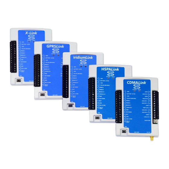
Page 1: Includes Gprslink, Iridiumlink, Hspalink And Cdmalink
X-Link Data Logger Operations & Maintenance Manual Includes GPRSLink, IRIDIUMLink, HSPALink and CDMALink Part No. 8800-1190 Rev 1.63 May 24, 2016... -
Page 2: Table Of Contents
Sutron Corporation X-Link Operations & Maintenance Manual, Rev 1.63 5/24/2016 pg. 2 TABLE OF CONTENTS Includes GPRSLink, IRIDIUMLink, HSPALink and CDMALink ..........1 Introduction ....................... 5 1.1. Models ........................6 1.2. Applications ......................6 1.3. Connections ......................7 1.4. Earth Ground Point....................8 1.5. - Page 3 Sutron Corporation X-Link Operations & Maintenance Manual, Rev 1.63 5/24/2016 pg. 3 8.6. Solar Radiation Sensor ..................106 8.7. SDI-12 Multi-Parameter Sensor ............... 107 8.8. ISCO Sampler triggering based on Stage ............108 8.9. Seametrics Flow Meter..................109 8.10. Computing Rate of Change ................112 Logging........................
- Page 4 18.3. Modbus Function Codes................... 172 18.4. Sutron Function Codes ..................174 19. Appendix A – Specifications ................181 20. Appendix B – Sutron Customer Service Policy ..........184 21. Appendix C – Commercial Warranty ..............185 21.1. Sutron Manufactured Equipment ..............185 21.2.
-
Page 5: Introduction
USB connection or remotely over cell, satellite, or Wi-Fi. LinkComm runs on Windows PC, OS X, iPhone/iPad, and Android platforms. X-Link was built to work with Sutron WIN. Sutron WIN makes it easy to collect data from multiple stations over different communication networks. Sutron WIN... -
Page 6: Models
5/24/2016 pg. 6 1.1. Models X-Link comes in several versions to meet varied customer needs. The table below shows the models currently offered. Check with Sutron for additional models or for a customized version of X-Link. Model Description X-Link-1 Basic unit with no modem, provides measurement and data logging... -
Page 7: Connections
Sutron Corporation X-Link Operations & Maintenance Manual, Rev 1.63 5/24/2016 pg. 7 1.3. Connections 1.3.1. USB Connector X-Link products come with a mini USB connector for connection to the USB port on a computer. X-Link uses the USB port for serial data communication only. -
Page 8: Earth Ground Point
Sutron Corporation X-Link Operations & Maintenance Manual, Rev 1.63 5/24/2016 pg. 8 1.4. Earth Ground Point A connection point has been provided for an Earth ground point. This critical connection always should be made first and should never be overlooked. - Page 9 Sutron Corporation X-Link Operations & Maintenance Manual, Rev 1.63 5/24/2016 pg. 9 Terminal Description Notes Block Main Battery/Power - + BATTERY (8-16V) Main Battery/Power + Solar Panel - + SOLAR (30W MAX) Solar Panel + RS485 A SDI-12 over RS-485, Modbus slave...
- Page 10 Sutron Corporation X-Link Operations & Maintenance Manual, Rev 1.63 5/24/2016 pg. 10 Terminal Description Notes Block AGND Analog ground Analog 0-5V ‘A’ Voltage input for sensors with 0-5V output AGND Analog ground Analog 0-5V ‘B’ Voltage input for sensors with 0-5V output DIFF ‘C’...
-
Page 11: Power Connections
Sutron Corporation X-Link Operations & Maintenance Manual, Rev 1.63 5/24/2016 pg. 11 1.7. Power Connections 1.7.1.1. Battery X-Link requires an external +12V power source to operate. The most common power source is a lead-acid or gel cell type battery. In the figure above, the battery and solar panel are shown connected Connect the battery to terminals #1 and #2 labeled - GND and + Battery (8-16V) on the external terminal strip. - Page 12 The Maximum battery size recommended for this charger is a 4AHr gel cell battery. If the station requires larger battery sizes, Sutron recommends using an external solar charger regulator such as the Sutron model 5100-0411 or similar.
- Page 13 Please see page 169 for details. 1.7.7.2. SDI-12 over RS-485 Sutron products such as the CF Bubbler support this connection. SDI-12 over RS- 485 is generally used to allow longer cable lengths. RS-485 does NOT provide power to the sensor. Do not forget to provide appropriate power to the sensor! 1.7.8.
-
Page 14: Wakeup Button
Sutron Corporation X-Link Operations & Maintenance Manual, Rev 1.63 5/24/2016 pg. 14 This line will output a voltage during the warmup for the following measurement types: analog, SDI-12, and digital. It will also always turn on when an analog measurement is made. -
Page 15: Getting Started
This indicates the X-Link is operating. 3. Download the LinkComm program. Go to http://www.sutron.com/downloads.htm, search on “LinkComm”, and download the installation package for your operating system, e.g., “Windows”, “OSX”, or “Android” (for “iOS”, please use App Store on your mobile device) o For Windows, extract all files to a folder on your computer. - Page 16 Sutron Corporation X-Link Operations & Maintenance Manual, Rev 1.63 5/24/2016 pg. 16 a. In the window that comes up, press “+” to create a new station. Set “Station type” to match your type of X-Link, set “Connect type” to “Serial”, and set “COM port” to the port assigned to X-Link b.
- Page 17 Sutron Corporation X-Link Operations & Maintenance Manual, Rev 1.63 5/24/2016 pg. 17 6. Select the Measurements tab. This is where you will set up X-Link to measure, process, and log data. If the unit is in its factory default condition, there will be no measurements enabled.
-
Page 18: Measurements
As a data logger, one of X-Link's primary functions is to measure and log data from sensors. All commonly used environmental sensors are supported. Here is a list of some of the sensors supported and available through Sutron: AT/RH (Air temperature and relative humidity) - using analog or SDI-12 sensors ... - Page 19 Sutron Corporation X-Link Operations & Maintenance Manual, Rev 1.63 5/24/2016 pg. 19 o Level digital inputs (read line state as 1 or 0) RS-485 o Support for certain sensors such as the Seametrics flow meter SDI-12 input o SDI-12 V1.3 compliant supports multiple sensors all connected to the same bus ...
-
Page 20: Linkcomm
Sutron Corporation X-Link Operations & Maintenance Manual, Rev 1.63 5/24/2016 pg. 20 4. LinkComm LinkComm is a software application designed to talk to X-Link. LinkComm is free. LinkComm is used to: Check X-Link status Set up an X-Link station ... -
Page 21: Sutron Corporation X-Link Operations & Maintenance Manual, Rev 1.63 5/24/2016 Pg
Sutron Corporation X-Link Operations & Maintenance Manual, Rev 1.63 5/24/2016 pg. 21 You use LinkComm’s “Stations List View” (sometimes called “Connect View”) to perform station management. This is the view you first see when LinkComm starts up. To add a new station, press the “+” button in the stations list header. To delete a station definition, select the station and then press the minus sign in the stations list header. - Page 22 There are several ways to connect to X-Link: Directly via USB cable Remotely via TCP/IP Remotely through the Sutron Redirector Locally via X-Link’s Wi-Fi Basic features, such as checking status and changing setup are available via all connection types.
- Page 23 Sutron Corporation X-Link Operations & Maintenance Manual, Rev 1.63 5/24/2016 pg. 23 connect to X-Link. This can be a considerable amount of data (several k-bytes). Here again, you may choose to disable this feature to reduce data costs. 4.1.2.1. Connecting via USB LinkComm can connect directly to X-Link via a USB cable.
- Page 24 SIM cards are behind a firewall, and so need special steps to be taken for access. When obtaining one of these SIM cards from Sutron, you will also receive a user name, password, and station name to use when setting up your station connection in LinkComm.
- Page 25 Sutron Corporation X-Link Operations & Maintenance Manual, Rev 1.63 5/24/2016 pg. 25 In order for LinkComm to connect to X-Link via Wi-Fi, the computer that is running LinkComm must first connect to the Wi-Fi hotspot provided by X-Link. To connect to X-Link via Wi-Fi, follow this sequence: 1.
-
Page 26: Station View - Connected Or Working Offline
See “About…” information Visit the Sutron website View the LinkComm event log (useful for debugging with customer service) Exit the app (not present on mobile app) 4.2. - Page 27 Sutron Corporation X-Link Operations & Maintenance Manual, Rev 1.63 5/24/2016 pg. 27 The main menu is accessed by pressing the button in the upper left. Different tabs are selected by pressing the tab buttons at the bottom of the view. The station view header contains two important buttons in the upper right, described next.
- Page 28 Sutron Corporation X-Link Operations & Maintenance Manual, Rev 1.63 5/24/2016 pg. 28 Pressing the setup status button typically prompts the user to take the next logical step towards getting the setup in-sync between LinkComm and X-Link, with recording on. Note: When the setup displayed by LinkComm is the same as the setup in X- Link, then we say the setups are “in-sync”.
- Page 29 Sutron Corporation X-Link Operations & Maintenance Manual, Rev 1.63 5/24/2016 pg. 29 4.2.3. Working with Setups Since both LinkComm and X-Link maintain separate setups, working with setups can be a bit tricky. This section explains how to work with setups in more detail, so you can be sure X-Link is always running the setup you intend.
- Page 30 Sutron Corporation X-Link Operations & Maintenance Manual, Rev 1.63 5/24/2016 pg. 30 When you later connect to X-Link, you need to send the setup to X-Link to bring the setups “in-sync”. If you checked “Get setup on connect” in the station’s Connection Settings, then when you first connect, LinkComm will prompt to overwrite your changes.
- Page 31 Start (or Stop, if applicable) recording* Help About… Display a dialog showing information about LinkComm, including version Sutron Website… Visit the Sutron website Event Log… Show LinkComm event log. This is a text file showing diagnostic information about LinkComm operation Exit...
-
Page 32: Dashboard Tab
Sutron Corporation X-Link Operations & Maintenance Manual, Rev 1.63 5/24/2016 pg. 32 4.3. Dashboard Tab The Dashboard tab is the first tab displayed after you connect to X-Link. When LinkComm connects to X-Link, it always retrieves the current station status, and current data values for measurements, and displays this data on the Dashboard. - Page 33 Sutron Corporation X-Link Operations & Maintenance Manual, Rev 1.63 5/24/2016 pg. 33 High level telemetry status is also shown on this page. To see low level details about telemetry, please see the Telemetry tab. If the station has any active errors, these are shown in RED just below the status area.
-
Page 34: Measurements Tab
Sutron Corporation X-Link Operations & Maintenance Manual, Rev 1.63 5/24/2016 pg. 34 4.4. Measurements Tab The measurements tab is the first tab displayed when you select Work Offline in the stations list view. This is the tab where all sensors are configured. Up to 16 sensors may be enabled and configured. - Page 35 Sutron Corporation X-Link Operations & Maintenance Manual, Rev 1.63 5/24/2016 pg. 35 To set up a sensor using a sensor template, press the Sensor Template… button. The following dialog is displayed. You browse for different available templates by pressing the arrows displayed over the sensor picture (which are only shown when the mouse hovers over them), or by using the Model: drop-down control.
- Page 36 Sutron Corporation X-Link Operations & Maintenance Manual, Rev 1.63 5/24/2016 pg. 36 4.4.2. Resetting Measurement Defaults A measurement entry can be reset to its default values by pressing the Mx Defaults button, which appears at the bottom of the Sensor settings section of the measurement settings, just above the schedule settings.
-
Page 37: Data Tab
Sutron Corporation X-Link Operations & Maintenance Manual, Rev 1.63 5/24/2016 pg. 37 4.5. Data Tab The data tab shows historical measurement readings made by X-Link. If recent data was downloaded when connecting to X-Link, the graph displays this data the first time you select the Data tab. -
Page 38: Telemetry Tab
Sutron Corporation X-Link Operations & Maintenance Manual, Rev 1.63 5/24/2016 pg. 38 4.6. Telemetry Tab The Telemetry tab is used to configure a station for Iridium or Cellular communications and data reporting. The contents of the tab differ for each telemetry type. - Page 39 Sutron Corporation X-Link Operations & Maintenance Manual, Rev 1.63 5/24/2016 pg. 39 Telemetry tab showing Iridium settings: 4.6.1. Telemetry Status Telemetry status is displayed on the telemetry tab, just below the telemetry setup. You may need to scroll down to see the status section.
-
Page 40: Other Setup
Sutron Corporation X-Link Operations & Maintenance Manual, Rev 1.63 5/24/2016 pg. 40 4.7. Other Setup Various settings are displayed in the Other Setup dialog, which is accessed from the Telemetry tab by pressing the Other Setup button. The settings shown include those for: ... -
Page 41: Diagnostics Tab
Sutron Corporation X-Link Operations & Maintenance Manual, Rev 1.63 5/24/2016 pg. 41 4.8. Diagnostics Tab This tab provides extensive diagnostics information, and offers tools for performing various diagnostics and maintenance operations. For example: Get diagnostics information including software versions and data usage ... - Page 42 Sutron Corporation X-Link Operations & Maintenance Manual, Rev 1.63 5/24/2016 pg. 42 4.8.2. LinkComm Versions and Diagnostics The bottom two text areas on the Diagnostics tab display information about LinkComm. The LinkComm Data Usage section displays the total byte counts between LinkComm and X-Link for the current session.
- Page 43 Sutron Corporation X-Link Operations & Maintenance Manual, Rev 1.63 5/24/2016 pg. 43 4.8.4. Data Flow The Data Flow dialog shows recent command line traffic expressed in terms of binary byte values, and shows traffic direction and timestamp information. To open the dialog, press the Data Flow button on the Diagnostic tab.
- Page 44 Sutron Corporation X-Link Operations & Maintenance Manual, Rev 1.63 5/24/2016 pg. 44 To send a command to an SDI-12 device connected to X-Link, enter the Address and Command fields, and then press the Send button. Be sure to check SDI-12 over RS-485, if you need to send the command over the RS-485 bus.
- Page 45 Firmware Upgrade The software running in X-Link can be upgraded. The latest version of X-Link firmware is delivered as part of the LinkComm download package obtained from the Sutron web site. LinkComm may be downloaded from http://www.sutron.com/downloads.htm (search on “LinkComm”).
-
Page 46: Linkcomm For Phones And Tablets
Sutron Corporation X-Link Operations & Maintenance Manual, Rev 1.63 5/24/2016 pg. 46 4.8.8. Setting to Factory Defaults Setting the station to factory defaults will permanently erase all setup and status. The setup will be set to defaults. To set X-Link to factory defaults, press the Factory Defaults button on the Diagnostics tab and answer “Yes”... - Page 47 Sutron Corporation X-Link Operations & Maintenance Manual, Rev 1.63 5/24/2016 pg. 47 4.9.2. Measurements List On phones and tablets, the measurements list is normally hidden, and must be accessed by selecting a link. To access the measurements list on the...
-
Page 48: Telemetry
Additionally, GPRSLink, HSPALink, and CDMALink units can be set up to receive incoming connections via the Listening feature. In this case, a program like the Sutron AutoPoll can be used to periodically gather data from X-Link. When scheduled transmissions are set up, X-Link initiates the data transfer; in Listening mode, an application starts the communication with X-Link. - Page 49 Sutron Corporation X-Link Operations & Maintenance Manual, Rev 1.63 5/24/2016 pg. 49 Scheduled: these transmissions occur periodically, a time designated by the user settings Tx Time and Tx Interval. Alarm: alarm transmissions happen when a sensor reading goes into alarm range.
-
Page 50: Retransmissions
Sutron Corporation X-Link Operations & Maintenance Manual, Rev 1.63 5/24/2016 pg. 50 5.2. Retransmissions Starting with version 1.57, X-Link is able to make retransmissions (ReTx). Retransmissions are retries of failed scheduled transmissions. When a scheduled transmission fails, X-Link notes the time of the failure. Once a future scheduled transmission succeeds, X-Link will proceed to re-transmit the data from the missing transmissions. -
Page 51: Cell Phone Telemetry
Sutron Corporation X-Link Operations & Maintenance Manual, Rev 1.63 5/24/2016 pg. 51 5.3. Cell Phone Telemetry GPRSLink, HSPALink, and CDMALink use the cell phone network to connect to the internet and deliver sensor data. The internet connection enables X-Link to get in touch with a server that will accept the sensor data. - Page 52 An X-Link can be set up to always be listening, which means that it will act as a server, accepting TCP/IP incoming connections. Sutron's AutoPoll PC software can periodically reach out to a listening X-Link station and collect sensor data from X-Link.
- Page 53 SMS notifications are meant to be sent to a customer's cell phone. They are meant to be immediately read by a person (rather than a computer, like Sutron WIN). SMS notifications are the way for a customer to receive notice a station in alarm on his cell phone.
- Page 54 Sutron Corporation X-Link Operations & Maintenance Manual, Rev 1.63 5/24/2016 pg. 54 2. The next line contains the event that caused the notification. It will look like the corresponding log entry except that there will be no timestamp. 3. The next line contains the measurement data for each active measurement that has a valid last reading.
- Page 55 Mode = SMS and Tx Mode = Internet Fallback SMS), the transmissions are expected to be received by a computer, such as Sutron WIN. It is not expected that the customer will receive those on a cell phone. These transmissions are formatted in whatever Tx Format the user selected, including Pseudobinary.
-
Page 56: Iridium Telemetry
Sutron Corporation X-Link Operations & Maintenance Manual, Rev 1.63 5/24/2016 pg. 56 5.4. Iridium Telemetry IRIDIUMLink uses the Iridium satellite constellation to deliver sensor data. Iridium satellite coverage is available everywhere. The diagram below shows how the signal travels through the Iridium Gateway to an email address, etc. -
Page 57: Sending Messages To X-Link
Sutron Corporation X-Link Operations & Maintenance Manual, Rev 1.63 5/24/2016 pg. 57 When installing the station, make sure IRIDIUM link consistently reports a signal strength of 4 or higher for at least 10 minutes. 5.4.2. Short Burst Data X-Link uses the Iridium Short Burst Data (SBD) capability to send transmissions and receive messages. - Page 58 Sutron Corporation X-Link Operations & Maintenance Manual, Rev 1.63 5/24/2016 pg. 58 When X-Link is turned on, it keeps the modem on for ten minutes. During that time, it will receive messages immediately. When it does receive a message, X- Link will keep the modem turned on for ten additional minutes to facilitate additional message conversations.
-
Page 59: Telemetry Status
Sutron Corporation X-Link Operations & Maintenance Manual, Rev 1.63 5/24/2016 pg. 59 The email's subject must be the IMEI of the Iridium modem. Each IRIDIUMLink will have its IMEI written on the front panel. Each transmission made by IRIDIUMLink will be stamped with its unique IMEI. - Page 60 Sutron Corporation X-Link Operations & Maintenance Manual, Rev 1.63 5/24/2016 pg. 60 5.6.1.2. Diagnostic Status IP Address (GPRSLink, HSPALink, and CDMALink only) Number of good, bad, and retried transmissions made lifetime Number of bytes transmitted today Number of bytes received today (GPRSLink and HSPALink only) ...
-
Page 61: Message Check
Sutron Corporation X-Link Operations & Maintenance Manual, Rev 1.63 5/24/2016 pg. 61 5.7. Message Check A message check is the process of using X-Link's modem to see if there are any messages waiting. For IRIDIUMLink, this means getting in touch with the gateway. -
Page 62: Optimizing Data Usage
Sutron Corporation X-Link Operations & Maintenance Manual, Rev 1.63 5/24/2016 pg. 62 It allows stations to go into lower power mode than if Listening were enabled. 5.8. Optimizing Data Usage The data contained in the transmission is largely dependent on the user setup variable Tx Data Content and the Tx Interval. -
Page 63: Transmissions And Measurements Coinciding
Sutron Corporation X-Link Operations & Maintenance Manual, Rev 1.63 5/24/2016 pg. 63 5.9. Transmissions and Measurements Coinciding Make sure to have the transmission scheduled a short while after the measurements are completed. If the measurements happen at the 15-minute mark, set the transmission time to 16 minutes to ensure the measurements are completed before the transmission process starts. -
Page 64: Alarms
Sutron Corporation X-Link Operations & Maintenance Manual, Rev 1.63 5/24/2016 pg. 64 6. Alarms Alarms are used to send immediate notifications when sensor readings read a certain threshold. They can also be used to control an output (page 120.) When a measurement is made, if alarms are enabled for that measurement, the sensor reading is compared to the Alarm Threshold and Alarm Deadband. - Page 65 Sutron Corporation X-Link Operations & Maintenance Manual, Rev 1.63 5/24/2016 pg. 65 6.1.1. Alarm Settings 6.1.1.1. Alarm 1, Alarm 2, and Alarm 3 Each of these settings can have one of the following values Off Hi Low ...
- Page 66 Sutron Corporation X-Link Operations & Maintenance Manual, Rev 1.63 5/24/2016 pg. 66 The system will log once every two minutes when in alarm, and once an hour when not in alarm. Measurement Interval = 00:02:00 Logging Interval = 01:00:00 Alarm Logging = Every Measurement...
- Page 67 Sutron Corporation X-Link Operations & Maintenance Manual, Rev 1.63 5/24/2016 pg. 67 If the absolute difference between the two readings (absolute of current reading minus past reading) is greater or equal to the Alarm Threshold, the station goes into alarm.
-
Page 68: Setup
Sutron Corporation X-Link Operations & Maintenance Manual, Rev 1.63 5/24/2016 pg. 68 7. Setup Once it is powered on, how X-Link operates is controlled by its setup. The user has the option of changing any part of the setup. The setup is stored in non- volatile memory and will not be affected when the unit loses power. - Page 69 Sutron Corporation X-Link Operations & Maintenance Manual, Rev 1.63 5/24/2016 pg. 69 Names and descriptions of each measurement setup field are described in the following sections. 7.1.1.1. Active Will X-Link make this measurement? If a measurement is not active, it will not be measured or logged.
- Page 70 Sutron Corporation X-Link Operations & Maintenance Manual, Rev 1.63 5/24/2016 pg. 70 Please note that if the setup is changed while X-Link is running, it may take up to twice the measurement interval before X-Link switches to the new schedule.
- Page 71 Sutron Corporation X-Link Operations & Maintenance Manual, Rev 1.63 5/24/2016 pg. 71 them. That result would be used as a sample. Once an hour, 60 samples would be averaged into a final result. Data collection starts at Measurement Time + Measurement Interval – Averaging Time + Sampling Interval, and the last sample is taken at Measurement Time + Measurement Interval.
- Page 72 Sutron Corporation X-Link Operations & Maintenance Manual, Rev 1.63 5/24/2016 pg. 72 wanted to log both the minimum and the maximum, it would be sufficient to set Details to enabled. 7.1.2. Logging Settings 7.1.2.1. Logging Interval Logging Interval dictates how often to log sensor data.
- Page 73 Sutron Corporation X-Link Operations & Maintenance Manual, Rev 1.63 5/24/2016 pg. 73 Maximum (the highest sample collected) Number of samples collected Details can only be enabled if averaging (see page 70) is taking place; otherwise, the number of samples would be 1, and the minimum and maximum would be equal to the final result.
- Page 74 Sutron Corporation X-Link Operations & Maintenance Manual, Rev 1.63 5/24/2016 pg. 74 The field Use Equations can be set to enabled or to disabled. It determines whether equation processing is to be applied to the raw data. The field Equation can be set to an ASCII string no longer than 128 bytes (per measurement).
- Page 75 Sutron Corporation X-Link Operations & Maintenance Manual, Rev 1.63 5/24/2016 pg. 75 ABS returns the absolute value of a real number. ABS(11.456) = 11.456 ABS(-1.345) = 1.345 POLY is used to compute up to a 5th level polynomial equation: POLY(x, A, B, C, D, E, F) equates to A + Bx + Cx^2 + Dx^3 + Ex^4 + Fx^5...
- Page 76 Sutron Corporation X-Link Operations & Maintenance Manual, Rev 1.63 5/24/2016 pg. 76 PULSE12(CONDUC=1, 100) If measurement CONDUC is equal to 1, then DOUT will activate for 100 ms. If it is not, nothing will happen. PULSE12(1, 500) Always pulses the DOUT line for 500ms PULSE12 will compute to 1 if DOUT was turned on;...
- Page 77 Sutron Corporation X-Link Operations & Maintenance Manual, Rev 1.63 5/24/2016 pg. 77 If both Equations and Slope and Offset are used, Slope and Offset are applied after the equation is processed. 7.1.3.6. Referencing other measurements If you are setting up an equation that references another measurement, set the measurement type to meta, and make sure the measurement time and interval are the same as the referenced measurement.
- Page 78 Sutron Corporation X-Link Operations & Maintenance Manual, Rev 1.63 5/24/2016 pg. 78 Below are listed all the Measurement Types available. 7.1.4.2. Precip Accumulation and Precip Rate Connection: Tipping bucket type sensor connected to terminals #8 and #9 X-Link can be set up with a tipping bucket in order to measure rainfall.
- Page 79 Sutron Corporation X-Link Operations & Maintenance Manual, Rev 1.63 5/24/2016 pg. 79 command, changing the sensor’s address from 0 to x, where x is a unique number or letter of your choice. 7.1.4.5. SDI-12 Command When the measurement type is set to SDI-12, data is obtained by sending a command to the SDI-12 sensor.
- Page 80 SDI-12 sensor as long as the sensor does not require to be powered on all the time. Some sensors (such as the Sutron SDR) need to be powered on all the time and will not work correctly if powered from the Switched Power line.
- Page 81 Sutron Corporation X-Link Operations & Maintenance Manual, Rev 1.63 5/24/2016 pg. 81 output into environmental units can be done via slope and offset for simple sensors, and via equations for non-linear sensors. 7.1.4.10. Analog Type This setting directs the input channel to which the sensor should be connected and the type of analog measurement to make.
- Page 82 Sutron Corporation X-Link Operations & Maintenance Manual, Rev 1.63 5/24/2016 pg. 82 The sensor will likely require power – connect that to VREF if 2.5V is appropriate or to +SW POWER which is 12V (or whatever power X-Link is supplied with).
- Page 83 Sutron Corporation X-Link Operations & Maintenance Manual, Rev 1.63 5/24/2016 pg. 83 Reading Negative Output Voltages on Differential Inputs: In limited cases, sensors with negative outputs may be used on the differential inputs with the following limitations: 1) The negative line from the sensor must not connect to the digital ground of the sensor with the sensor making a ground connection to the ground (including antenna ground) of the X-Link logger.
- Page 84 Sutron Corporation X-Link Operations & Maintenance Manual, Rev 1.63 5/24/2016 pg. 84 The common mode voltage for differential sensors is 0.5V to 3.7V. If the sensor is floating, it should be tied to VREF and not to AGND in order to maintain this common mode voltage.
- Page 85 Sutron Corporation X-Link Operations & Maintenance Manual, Rev 1.63 5/24/2016 pg. 85 NOTE: X-Link does not provide a dedicated power supply for 4-20ma sensors. The sensor shall have its own supply or run off the 12 volt supply of X-Link.
- Page 86 Sutron Corporation X-Link Operations & Maintenance Manual, Rev 1.63 5/24/2016 pg. 86 Wind sensors, sometimes referred to as anemometers, provide two readings: wind speed and wind direction (sometimes referred to as azimuth). Wind speed is expressed in units of velocity (mph, kph, etc), while wind direction is expressed in degrees (0 to 360).
- Page 87 Sutron Corporation X-Link Operations & Maintenance Manual, Rev 1.63 5/24/2016 pg. 87 o Mean Direction Unit – This is the wind direction (in degrees) not weighted for wind speed. Here, the average of 10mph at 0 with 20mph at 90 is 45.
- Page 88 Sutron Corporation X-Link Operations & Maintenance Manual, Rev 1.63 5/24/2016 pg. 88 Counter type readings may be optionally debounced for 3ms using the debounce setting. The 3ms debouncing eliminates false counts from tipping buckets and other devices with noisy switches.
- Page 89 1.8 and the offset to 32. 7.1.4.26. Accubar Pressure And Temperature Sutron provides Accubar Barometric Pressure and Temperature sensors which can be connected to X-Link via an internal connector. By default, the sensors produce an atmospheric pressure reading in millibars and...
- Page 90 Sutron Corporation X-Link Operations & Maintenance Manual, Rev 1.63 5/24/2016 pg. 90 use the Slope and Offset settings. Multiply millibars by 0.02952998 to get inches of Mercury at 0C (inHg). Multiply millibars by 0.01450377 to convert to PSI. Each Accubar reading takes a bit longer than one second to complete. If two Accubar measurements coincide, a single sensor reading is made and the result shared between all the measurements.
- Page 91 Sutron Corporation X-Link Operations & Maintenance Manual, Rev 1.63 5/24/2016 pg. 91 11:00 measure and log data 11:15 measure and log data 11:30 measure and log data 11:45 measure and log data 11:50 transmission Setup options: ...
-
Page 92: Telemetry Setup
Sutron Corporation X-Link Operations & Maintenance Manual, Rev 1.63 5/24/2016 pg. 92 7.1.9. Measurement Two-Point Calibration Changing the slope and offset of a measurement can be accomplished by using the automated two point calibration. You will need to be able to affect the sensor so that it can provide two different readings. - Page 93 GPRSLink, HSPALink, and CDMALink will be able to receive incoming connections too. Setting up your GPRSLink with Tx Enable disabled and Listening enabled is a valid setup in which software like Sutron WIN may periodically get data from the station. 7.2.1.2.
- Page 94 The CSV format is an extremely verbose human readable format only suitable for diagnostics. It's full name is Sutron Standard CSV and it is the same format that X-Link's downloaded logs are in. Here is an example of the format: 09/14/2009,12:30:00,TEMP,28.5...
- Page 95 Sutron Corporation X-Link Operations & Maintenance Manual, Rev 1.63 5/24/2016 pg. 95 7.2.1.6. Max Tx Time The Max Tx Time setting dictates how long X-Link will continue to attempt to make a transmission. The default value is 10 minutes. The goal of this setting is to reduce power consumption when there is a transmission problem, such as no network for cellular stations or no satellite view for Iridium stations.
- Page 96 Sutron Corporation X-Link Operations & Maintenance Manual, Rev 1.63 5/24/2016 pg. 96 7.2.2.6. SMS Tx Phone A See Below. 7.2.2.7. SMS Tx Phone B See Below. 7.2.2.8. SMS Tx Phone C When it is time to make a scheduled transmission, if Tx Mode is set to SMS, X- Link will send data to the phone number(s) set up in SMS Tx Phone.
- Page 97 If SMS Listening Only is disabled, GPRSLink will always be connected to the internet. It will keep a TCP/IP listening socket open on the Listen Port. Programs like LinkComm, HyperTerminal, Sutron WIN, can get in touch with X-Link immediately in order to download data, change setup, or perform any other activity.
-
Page 98: Other Setup
Sutron Corporation X-Link Operations & Maintenance Manual, Rev 1.63 5/24/2016 pg. 98 The time may be initially set using the Set Clock button on the diagnostic tab to ensure it is close to the time desired, otherwise, the time will be UTC until it does the clock sync at the next transmission. - Page 99 Sutron Corporation X-Link Operations & Maintenance Manual, Rev 1.63 5/24/2016 pg. 99 7.3.1.5. Output1 X-Link features a digital output labeled DOUT. X-Link can automatically activate the output. See the Output section for details (page 120.) 7.3.1.6. Modbus All Modbus settings are described in the Modbus section (page 169).
-
Page 100: Measurement Setup Examples
Sutron Corporation X-Link Operations & Maintenance Manual, Rev 1.63 5/24/2016 pg. 100 8. Measurement Setup Examples 8.1. RM Young Wind Speed and Direction This section describes how to connect the sensor and how to set up X-Link in order to measure wind speed and direction. The sensor used is an RM Young 05103-11 which has a four-blade propeller for speed and a vane for direction. -
Page 101: Thermistor
Sutron Corporation X-Link Operations & Maintenance Manual, Rev 1.63 5/24/2016 pg. 101 Wind Direction Setup Value Wind Type Wind Dir Analog Analog Type 0-5V A Warmup 0 sec Averaging Time 00:00:10 Sampling Interval 1.0 sec Use Equation Equation X/VREF*355 {converts to degrees} Some settings have been excluded from the table above. -
Page 102: Pressure Transducer (Analog Bridge Sensor)
Sutron Corporation X-Link Operations & Maintenance Manual, Rev 1.63 5/24/2016 pg. 102 Meas Type Analog Analog Type 0-5V A (or B) Warmup 0 sec Averaging Time 00:00:00 Sampling Interval 0.0 sec Slope 1 for Celsius 1.8 for Fahrenheit Offset 0 for Celsius... - Page 103 Sutron Corporation X-Link Operations & Maintenance Manual, Rev 1.63 5/24/2016 pg. 103 Pressure Transducer Pin COLOR Terminal Block Description Description WHITE AGND Negative Supply VREF Positive Supply DIFF ‘C’ (+) YELLOW Positive Output DIFF ‘C’ (- ) BLUE Negative Output Connect the shield wire on the pressure transducer to the earth ground on the side of the X-Link.
-
Page 104: Thermocouple Sensor
Sutron Corporation X-Link Operations & Maintenance Manual, Rev 1.63 5/24/2016 pg. 104 8.4. Thermocouple Sensor The thermocouple sensor is a common sensor for temperature readings. This application note will show operation using the Type K thermocouple. This sensor outputs a voltage that represents the difference in temperature from the terminal block to the junction of the wires. -
Page 105: Tipping Bucket
Sutron Corporation X-Link Operations & Maintenance Manual, Rev 1.63 5/24/2016 pg. 105 To have an absolute temperature reading, you must measure the temperature of the terminal strip and then add to it the thermocouple temperature. K-Type Equations: Linear delta T range of ± 20°C. Approximation error is ±0.20°C. -
Page 106: Solar Radiation Sensor
Sutron Corporation X-Link Operations & Maintenance Manual, Rev 1.63 5/24/2016 pg. 106 Tipping Bucket X-Link Connections Lead 1 TB/DIG IN 2 Terminal #8 Lead 2 GND Terminal #9 Tipping Bucket Setup Value (Total Rain) Active Label RAIN Meas Type Precip Accumulation... -
Page 107: Multi-Parameter Sensor
Sutron Corporation X-Link Operations & Maintenance Manual, Rev 1.63 5/24/2016 pg. 107 + SIG Diff C + - SIG Diff C - This X-Link setup will measure solar radiation, in units of Watts per m², from the sensor that has a sensitivity of 79.4uV / Wm² (.0000794 V/ Wm²). -
Page 108: Isco Sampler Triggering Based On Stage
Sutron Corporation X-Link Operations & Maintenance Manual, Rev 1.63 5/24/2016 pg. 108 Wind speed Setup Value M1 Active Label SDI0P1 Meas Type SDI-12 SDI-12 Address SDI-12 Command SDI-12 Param Meas Interval 00:15:00 Meas Time 00:00:00 Averaging Time 00:00:00 M2 Active... -
Page 109: Seametrics Flow Meter
Sutron Corporation X-Link Operations & Maintenance Manual, Rev 1.63 5/24/2016 pg. 109 This X-Link setup measures the STAGE parameter from a single SDI-12 sensor in Measurement 1 and then uses that value to determine when to trigger the ISCO sampler. Note: In this setup, the M2 equation determines if the STAGE is greater than 7.75, then it will pulse the DOUT for 1000mS (1 second). - Page 110 Sutron Corporation X-Link Operations & Maintenance Manual, Rev 1.63 5/24/2016 pg. 110 8.9.1. Hardware Interface The Seametrics flow meter connects to X-Link's RS-485 interface. External signal conditioning is required to connect a Seametrics flow meter to X-Link . Refer to diagram below to wire a Seametrics meter to an X-Link.
- Page 111 Sutron Corporation X-Link Operations & Maintenance Manual, Rev 1.63 5/24/2016 pg. 111 The only reason to change X-Link's Timeout setting is if there are SDI-12 sensors connected. The RS-485 bus used to connect to Seametrics is shared with the SDI-12 bus. As long as X-Link is listening for data from the Seametrics flow meter, it cannot collect data from any SDI-12 sensors.
-
Page 112: Computing Rate Of Change
Sutron Corporation X-Link Operations & Maintenance Manual, Rev 1.63 5/24/2016 pg. 112 10 seconds was added to ensure that a reading was not missed due to minor timing issue. As long as the SDI-12 sensor takes less than 50 seconds to complete, there should be no issues getting data from both sensors. -
Page 113: Sutron Corporation X-Link Operations & Maintenance Manual, Rev 1.63 5/24/2016 Pg
Sutron Corporation X-Link Operations & Maintenance Manual, Rev 1.63 5/24/2016 pg. 113 For this setup, DeltaT1 is always 10. Note that the equation becomes quite complicated if it needs to account for a rollover value. -
Page 114: Logging
measurement reading (optional) measurement quality (optional) The format of logged data is the Sutron Standard CSV format, which was introduced in the 2009. It is a format common to current Sutron products. The general format specification for Sutron Standard CSV format is:... -
Page 115: Log Events
X-Link Operations & Maintenance Manual, Rev 1.63 5/24/2016 pg. 115 The downloaded data is in Sutron Standard CSV format and can be easily displayed using Sutron’s GRAPHER program (downloadable from www.sutron.com) or common spreadsheet/word processing programs. You can download the whole log or only parts of it. You may specify the start date and optionally the end date for the downloaded data. - Page 116 Sutron Corporation X-Link Operations & Maintenance Manual, Rev 1.63 5/24/2016 pg. 116 Event Description Condition: A transmission is successfully completed. Time logged: The time the transmission processes started, which may be Tx Good minutes before it completed, depending on signal strength.
- Page 117 Sutron Corporation X-Link Operations & Maintenance Manual, Rev 1.63 5/24/2016 pg. 117 Event Description Condition: Logged when X-Link is powered on. Logged with the cumulative total number of power on resets. If that number is Reset 100, it means it is the 100 time the unit was powered on.
- Page 118 Sutron Corporation X-Link Operations & Maintenance Manual, Rev 1.63 5/24/2016 pg. 118 Event Description Failure Time logged: Logged only the first time the sensor fails and it gets logged only once a day. Value logged: The value logged is the index of the measurement that failed.
-
Page 119: Password
Sutron Corporation X-Link Operations & Maintenance Manual, Rev 1.63 5/24/2016 pg. 119 Password Password protection can be configured to prevent unauthorized access. If password protection is enabled, a user who is connected via USB can view setup and data. However, no changes to setup are allowed until a password is entered. -
Page 120: Output
Sutron Corporation X-Link Operations & Maintenance Manual, Rev 1.63 5/24/2016 pg. 120 Output X-Link features a digital output. X-Link's digital output line is on terminal #11 and is labeled DOUT. The digital output may be activated via several means. Manually via command line. A command may be sent using... -
Page 121: Output Hardware
Sutron Corporation X-Link Operations & Maintenance Manual, Rev 1.63 5/24/2016 pg. 121 Command line access to output 1: OUTPUT1 tells whether the output is currently on. X-Link's possible replies: Output1 is NOT active Output1 is ACTIVE OUTPUT1 ON turns on the output ... - Page 122 Sutron Corporation X-Link Operations & Maintenance Manual, Rev 1.63 5/24/2016 pg. 122 With a pull-up resistor connected o When the output is turned on, the output syncs current from all attached devices. o When the output is turned off, the output is pulled up to the supplying...
-
Page 123: Time Keeping
Sutron Corporation X-Link Operations & Maintenance Manual, Rev 1.63 5/24/2016 pg. 123 Time Keeping To keep time, X-Link uses an RTC (real time clock) backed by an internal battery. The RTC keeps ticking even if the main battery to the X-Link is removed. The RTC will, at worst case, drift ±2 minutes per month (0 to +50C). -
Page 124: Sdi Clock Synchronization
12.2. SDI Clock Synchronization Certain Sutron SDI-12 sensors (such as the SDR, RLR, and the CF Bubbler) support a command to set the time of the sensor via SDI-12. X-Link takes advantage of that feature, and periodically sets the clock of the sensors using an SDI-12 command, ensuring that all devices share a common time. -
Page 125: Errors
Sutron Corporation X-Link Operations & Maintenance Manual, Rev 1.63 5/24/2016 pg. 125 Errors During operation, X-Link may notice system errors. If it does, it will blink the red LED on the front panel. To see the error details, check the status with LinkComm. Via command line, type STATUS to see any potential errors. -
Page 126: System Errors
Sutron Corporation X-Link Operations & Maintenance Manual, Rev 1.63 5/24/2016 pg. 126 The system missed a scheduled measurement (likely due to measurement taking longer than Meas Interval to complete – e.g. system was told to measure every 5 seconds even though the sensor takes 10 seconds to finish a reading ... - Page 127 Every hardware error has a code logged with it. A hardware error usually indicates a serious problem with the unit. Contact Sutron customer support at 703 406 2800 for help with hardware errors. 13.3.5.
-
Page 128: Command Line Interface
Sutron Corporation X-Link Operations & Maintenance Manual, Rev 1.63 5/24/2016 pg. 128 Command Line Interface The best way to set up and talk to X-Link is by using LinkComm software. Connect X-Link to a PC via a USB cable, install any required drivers, and run LinkComm. -
Page 129: Sending Messages
Sutron Corporation X-Link Operations & Maintenance Manual, Rev 1.63 5/24/2016 pg. 129 While it is not recommended, changing the baud rate can be done by typing BAUD RATE. The default baud rate is 115200. With the terminal program, if the emulation is set for VT100, pressing the up arrow brings back the last typed command. -
Page 130: Status
Recording or Tx Enable. 14.4. Status To check the status, type STATUS (or just S). >STATUS X-Link: X-Link ver 1.04 Station Name = SUTRON DEV1 System In Alarm Measurement M1 STAGE reading 10.16 2012/03/30 12:10:15 Into Alarm Recording = On 4 Meas Active GPRS Modem: Off. - Page 131 >STATION NAME = SUTRON DEV 1 Setup changed Station Name = SUTRON DEV 1, max length 23 Changing measurement setup fields requires that the measurement be named. For example, to change the Measurement Type it is not enough to type MEAS TYPE.
-
Page 132: Measurements
Sutron Corporation X-Link Operations & Maintenance Manual, Rev 1.63 5/24/2016 pg. 132 Setting the whole setup to defaults can be accomplished by typing SETUP DEFAULTS. Setting just measurement one to defaults can be done via M1 SETUP DEFAULTS. 14.6. Measurements To view the setup and the last reading made measurement one, type M1. -
Page 133: Recording
Sutron Corporation X-Link Operations & Maintenance Manual, Rev 1.63 5/24/2016 pg. 133 Slope = 0.709607 Offset = 13.297492 14.7. Recording By default, X-Link is not running. That means that it is neither making measurements nor recording data. To start X-Link, click the Start button in LinkComm, or type RECORDING = ON. -
Page 134: Examples
Sutron Corporation X-Link Operations & Maintenance Manual, Rev 1.63 5/24/2016 pg. 134 14.9. Examples Following is the captured communication of a user setting up measurement one for a battery voltage measurement, making a measurement, and turning recording on. >M1 ACTIVE = 1... -
Page 135: Machine-To-Machine Communication
E.g. STATION NAME will show the current name. Every setup variable can be changed by typing its name = new value. E.g. STATION NAME = STURON will set the current name to SUTRON. For a list of all the setup names, see the Setup section. - Page 136 Sutron Corporation X-Link Operations & Maintenance Manual, Rev 1.63 5/24/2016 pg. 136 14.12.1. List of Commands Command Description This command is used to help with antenna placement. Once issued, X-Link will keep the modem on and output the signal strength every few seconds. The output will continue until the user presses a key, disconnects, or after 30 minutes.
- Page 137 That includes each setup variable and its current value. Can be followed by a setup variable name and a new value for that variable. E.g. STATION NAME = SUTRON If SETUP DEFAULT is issued, it will reset the entire setup to defaults. STATUS 0...
- Page 138 Sutron Corporation X-Link Operations & Maintenance Manual, Rev 1.63 5/24/2016 pg. 138 Command Description TXBUF This command shows the data content of the transmission buffer. Normally, the transmission buffer will contain data from the last transmission. The transmission buffer can hold...
-
Page 139: Upgrading Firmware
LinkComm section for those details. (page 20.) Upgrades may only be done when directly connected to the USB port on X-Link. Upgrade files for X-Link can be downloaded from www.sutron.com. X-Link upgrade files will have names such as v1_05mainXLINK1298.upg and v1_01bootOMEGA1298.upg. - Page 140 Sutron Corporation X-Link Operations & Maintenance Manual, Rev 1.63 5/24/2016 pg. 140 3. Make sure serial drivers are installed (see the USB Connector section). 4. Run a terminal program such as HyperTerminal on the PC. 5. Select the correct communications port (e.g. COM1).
-
Page 141: Collecting Data
Sutron provides the Iridium service in a bundled plan that includes 12Kbytes of data for a low monthly fee. Every additional 1024 bytes cost $1.50. - Page 142 5/24/2016 pg. 142 The delivery of data via the internet is via e-mail and/or direct IP. Sutron uses Direct IP in its SutronWin and Tempest products. The protocol delivers the messages within 5 seconds of their reception by the gateway. Sutron only uses the e-mail delivery of messages in tests.
- Page 143 5/24/2016 pg. 143 Sutron’s GPRS service is supported by T-Mobile and AT&T and their roaming partners in the United States. The TGPRS plan is the standard one to use in the US. This plan uses T-Mobile infrastructure. The WGPRS plan expands the footprint by supporting AT&T and roaming partners.
-
Page 144: Decide Where You Want The Data To Be Transmitted
Sutron Corporation X-Link Operations & Maintenance Manual, Rev 1.63 5/24/2016 pg. 144 ordered by Sutron will receive a static, private IP address for easy two-way access to the station. (see the section above for more information on static/private IP addresses). 15.2. -
Page 145: Estimate Communications Costs
If you are going to use your own station, plan on the following: Run Sutron’s AutoPoll (GPRS/CDMA) or Tempest software (GPRS/CDMA/IRIDIUM). Consult Sutron if you have your own SW/system and you’d like to receive directly the messages from the field stations. - Page 146 Sutron Corporation X-Link Operations & Maintenance Manual, Rev 1.63 5/24/2016 pg. 146 Measurement Interval = 01:00:00 Transmit Interval = 01:00:00 Wyless Wyless GPRS Bytes/Msg B/Msg B/Month TGPRS.1MB Sheffix 256 KB $10.00 Pseudobinary B 248 KB $10.00 Pseudobinary C 257 KB $10.00...
- Page 147 Sutron Corporation X-Link Operations & Maintenance Manual, Rev 1.63 5/24/2016 pg. 147 15.3.3. Example 3: Measuring One Value Every 15 Minutes and Transmitting it Every 15 Minutes Wireless Cost Calculator (Fill in all yellow boxes) Unit Name = Omega # of Sensors =...
-
Page 148: Sign The Agreement
15.4. Sign the Agreement Sutron has a standard agreement you must sign before Sutron will activate a modem. In the agreement, you agree to pay for overage charges and you acknowledge that service is not guaranteed. Contact Sutron for a copy of the... -
Page 149: Place The Order
Be aware that SMS is not available with all providers and is optional on some plans. If you have your own SIM card (not from Sutron) be aware that most SIM cards give the modem a private, dynamic IP address. You cannot initiate communications with a modem that has a dynamic IP–... - Page 150 Sutron Corporation X-Link Operations & Maintenance Manual, Rev 1.63 5/24/2016 pg. 150 ISBD.ACT One-time Iridium modem activation fee ISBD.OK.1 Minimum monthly fee with no data plan ISBD.12KB.PLAN Minimum monthly fee with 12KB data included (every 1KB after the initial 12KB is charged at the ISBD.1KB.ADDL rate).
- Page 151 SCDMA.1MB.ADDL Overage charge per MB SCDMA.SMS Each 15.6.4. GPRS International Contact Sutron about operation in Canada. 15.6.4.1. WYLESS INTERNATIONAL GPRS -- INTERNATIONAL WIGPRS.ACT Activation - one time charge Monthly plan - per month – Zone 1 – WIGPRS.1MBZ1 PLAN 1MB included Monthly plan - per month –...
- Page 152 Sutron Corporation X-Link Operations & Maintenance Manual, Rev 1.63 5/24/2016 pg. 152 15.6.5. VPN connection - only needed if customer is not using SutronWin and/or wants to initiate connection to field station WVPN.IPSEC One time charge WVPN.PPTP One time charge...
-
Page 153: Data Formats
Sutron Corporation X-Link Operations & Maintenance Manual, Rev 1.63 5/24/2016 pg. 153 Data Formats 16.1. TCP/IP Session GPRSLink, HSPALink, and CDMALink use scheduled transmissions periodically connect to a server and deliver sensor data. See the Cell Phone Telemetry and Cell Phone Settings sections for more details, beginning on page Relevant settings include Main Server, Backup Server, Server Port, and Server Password. -
Page 154: Iridium Telemetry Header
Sutron Corporation X-Link Operations & Maintenance Manual, Rev 1.63 5/24/2016 pg. 154 9. If user login matches, X-Link enters command-line session. 10. Server issues pending commands, and X-Link processes and responds accordingly. 11. When command processing complete, the server disconnects. - Page 155 Sutron Corporation X-Link Operations & Maintenance Manual, Rev 1.63 5/24/2016 pg. 155 o packet-type o sub-header o data The packet-type is a single byte: Hex Value ASCII Description 0x30 Self-timed 0x31 Self-timed extended 0x32 Entering alarm 0x33 Entering alarm extended...
-
Page 156: Pseudobinary B Data Format
Sutron Corporation X-Link Operations & Maintenance Manual, Rev 1.63 5/24/2016 pg. 156 16.2.2.2. Example 2 The same data in SHEF format: Self-timed 0:HG 0 #1 42.00 42.00 42.00 :EM 0 #1 69.00 69.00 69.00 Entering Alarm 2:HG 0 #1 42.00 42.00 42.00 :EM 0 #1 69.00 69.00 69.00 Exiting Alarm 4:HG 0 #1 42.00 42.00 42.00 :EM 0 #1 69.00 69.00 69.00... -
Page 157: Pseudobinary C Data Format
All the required values for one sensor (most recent first) before proceeding to the next measurement. This format is similar to that used by the Sutron Satlink but different from the 8210. BATTERY VOLTAGE This is the battery voltage measured prior to making the transmission. - Page 158 All the required values for one sensor (most recent first) before proceeding to the next measurement. This format is similar to that used by the Sutron Satlink but different from the 8210. There will be 3 bytes of encoded data for every sensor reading.
-
Page 159: Pseudobinary D Data Format
Sutron Corporation X-Link Operations & Maintenance Manual, Rev 1.63 5/24/2016 pg. 159 M1 Right Digits M1 Meas Interval 00:01:00 M1 Tx Data Content All Logged M2 Right Digits M2 Meas Interval 00:01:00 M2 Tx Data Content Last Tx Time 00:00:30... - Page 160 All the required values for one sensor (most recent first) before proceeding to the next measurement. This format is similar to that used by the Sutron Satlink but different from the 8210. There will be 3 bytes of encoded data for every sensor reading.
-
Page 161: Six Bit Binary Encoded Format
Sutron Corporation X-Link Operations & Maintenance Manual, Rev 1.63 5/24/2016 pg. 161 M1 Right Digits M1 Meas Interval 00:01:00 M1 Tx Data Content All Logged M2 Right Digits M2 Meas Interval 00:05:00 M2 Tx Data Content Last Tx Time 00:00:30... - Page 162 Sutron Corporation X-Link Operations & Maintenance Manual, Rev 1.63 5/24/2016 pg. 162 16.6.1. Example 1: Encoding the Number 10 in 1 Byte Since 10 will fit in 6-bits we only have to add 64 which would yield 74. So the number 10 would appear as ASCII 74 or the letter J.
-
Page 163: Pseudobinary Over Sms
Replacement Byte ASCII 16.8. SHEF and SHEFFIX Data Format SHEF is a format that is commonly used by Sutron's Satlink satellite transmitter. It is an ASCII format that is easy to read and contains some self-descriptive information. The format of the transmission data is: : <LABEL1>... - Page 164 Sutron Corporation X-Link Operations & Maintenance Manual, Rev 1.63 5/24/2016 pg. 164 DATA This is data collected and logged by X-Link through measurements. Only logged data may be transmitted. If Tx Data Content is set to Exclude, no data from that measurement will be transmitted.
-
Page 165: Sutron Standard Csv
16.9. Sutron Standard CSV Logs downloaded from X-Link will be in the Sutron Standard CSV format. It is possible to transmit data in the CSV format. However, CSV messages are too large for most applications and are generally used to help set up a station. -
Page 166: More About Sdi-12
Sutron Corporation X-Link Operations & Maintenance Manual, Rev 1.63 5/24/2016 pg. 166 More about SDI-12 17.1. Overview SDI-12 is a standard for interfacing data recorders with microprocessor-based sensors. SDI-12 stands for serial data interface at 1200 baud. SDI-12 is intended for applications with the following requirements: ... -
Page 167: Wiring Guidelines
water velocity weight of snow and ice on a snow pillow wind speed and direction Sutron also offers general purpose interfaces for making analog and digital measurements via SDI-12. For more information on SDI-12, go to www.sdi-12.org. -
Page 168: Useful Sdi Commands
Sutron Corporation X-Link Operations & Maintenance Manual, Rev 1.63 5/24/2016 pg. 168 When setting up multiple SDI-12 sensors, connect one sensor at a time. Once a new sensor is connected, you must give it a unique address. To do so, either use LinkComm or the command line. -
Page 169: Modbus
Sutron Corporation X-Link Operations & Maintenance Manual, Rev 1.63 5/24/2016 pg. 169 Modbus Modbus is a communications protocol commonly used in industrial applications. Please see the Wikipedia entry for more details. X-Link can be configured as a Modbus slave device. That means that some other Modbus master can collect data from X-Link. -
Page 170: Modbus Setup
Listen Port: This is the port that the Modbus master will use to access X-Link. The Listen Port setting in X-Link must match the Modbus master's port setting. Sutron provides Autopoll software which is capable of accessing X-Link using the Modbus protocol over cell. For more information on AutoPoll, please visit www.sutron.com. - Page 171 Sutron Corporation X-Link Operations & Maintenance Manual, Rev 1.63 5/24/2016 pg. 171 18.2.1.2. Modbus Cell Protocol Within Modbus, there are different protocols: RTU ASCII TCP RTU is the most basic Modbus protocol and is commonly used for directly wired systems.
-
Page 172: Modbus Function Codes
0x0C Diagnostic 0x08 Return Bus Exception Count 0x0D Diagnostic 0x08 Return Slave Message Count 0x0E Diagnostic 0x08 Return Slave Broadcast Count 0x0F Diagnostic 0x08 Return Bus Char Overrun Count 0x12 Write Multiple Registers 0x10 Sutron Function Code 0x41 Get Log... - Page 173 Sutron Corporation X-Link Operations & Maintenance Manual, Rev 1.63 5/24/2016 pg. 173 Sutron Function Code 0x41 Get File Sutron Function Code 0x41 Send File 18.3.1. Identifying Registers There are two types of data that can be accessed using the Modbus protocol.
-
Page 174: Sutron Function Codes
309 and 310 and combine the result into a single 32 bit IEEE floating point value. 18.4. Sutron Function Codes This section describes the use of the Sutron function code to get files, send files and, get the log over MODBUS. - Page 175 5/24/2016 pg. 175 The data portion of a packet carrying the Sutron function code (function code 65, or 0x41) contains a subcode and associated parameters to define the particular function to perform. The subcode and its parameters are expressed using ASCII characters.
- Page 176 Sutron Corporation X-Link Operations & Maintenance Manual, Rev 1.63 5/24/2016 pg. 176 The datetime value in the response message is the datetime of the returned record and, therefore, may be different from the datetime in the GetLog command statement. The data to the end of the file can be read by leaving datetime at the desired starting point and incrementing recordID until the status indicates record not found.
- Page 177 Sutron Corporation X-Link Operations & Maintenance Manual, Rev 1.63 5/24/2016 pg. 177 accepted by X-Link. If the value provided is too small, the command may fail. To be safe, use 128, 255, or, best of all, *. X-Link will reply to the GF command like so:...
- Page 178 Access recent measurements and setup details by asking for the file "sensors.txt". The data in the file will describe the measurement setup along with the most recent radings. The data mimic's Sutron 9210's sensor view. Tab characters are used to denote column breaks. Each line is terminated by a CR/LF.
- Page 179 Sutron Corporation X-Link Operations & Maintenance Manual, Rev 1.63 5/24/2016 pg. 179 18.4.2.4. Setup X-Link's setup may be read by asking for "setup.txt". The data returned will be exactly the same as that of a saved LinkComm setup file. !Station Name=XLINK...
- Page 180 Sutron Corporation X-Link Operations & Maintenance Manual, Rev 1.63 5/24/2016 pg. 180 STATION NAME = HAPPY CREEK M1 MEAS INTERVAL = 00:00:30 The format of the reply is as follows: SFR,status,bytepos,numbytes The value of status can be any of the following values:...
-
Page 181: Appendix A - Specifications
Sutron Corporation X-Link Operations & Maintenance Manual, Rev 1.63 5/24/2016 pg. 181 Appendix A – Specifications ELECTRICAL Input Voltage 8-16VDC 10 V minimum for SDI-12 sensor support Reverse power protected @ 12V URRENT ONSUMPTION Standby (all sensors unpowered) 0.5mA typical... - Page 182 USB port 1 Mini-B Male 5 pin USB connector designed to be connected to USB Type-A Male on Windows PC. Sutron provides ‘LinkComm’ software for USB port communications Not a full function USB port. SDI-12 INTERFACE Supports up to 16 SDI-12 sensors ...
- Page 183 Sutron Corporation X-Link Operations & Maintenance Manual, Rev 1.63 5/24/2016 pg. 183 4-20 A ANALOG INPUT Range 0 - 22mA Resolution <1nA Accuracy @25⁰C 0.02% Loop Power External Loop Resistance 200 Ohm TEMPERATURE MEASUREMENT (I NTERNAL Range -40°C to +60°C Accuracy ±...
-
Page 184: Appendix B - Sutron Customer Service Policy
Of course not all problems can be fixed over the phone. Sometimes a customer needs an on-site technician to identify site related problems or troubleshoot a network. Sutron can provide these services at a reasonable cost. Call for details. If you would like to learn more about Sutron products email sales@sutron.com... -
Page 185: Appendix C - Commercial Warranty
Sutron’s plant. Sutron’s obligation under this Warranty shall be limited to repair at the factory (22400 Davis Drive, Sterling, VA 20164), or at its option, replacement of defective product. -
Page 186: Repair And Return Policy
21.3. Repair and Return Policy Sutron maintains a repair department at the factory, 22400 Davis Drive, Sterling, VA 20164. Turnaround time normally ranges from 10-30 days after Sutron receives equipment for repair. Call Customer Service at (703) 406-2800 for a Return Material Authorization (RMA) number. -
Page 187: Appendix D - Installation
2. Wall Panel Mount System. 3. Din Rail Mount System. Sutron NEVER recommends direct outdoor mounting of the product as it is not a sealed waterproof enclosure. Sutron also recommends mounting the X-link in an enclosure under all circumstances as leaving the exposed X-Link to wet and humid gauge houses... -
Page 188: Power Budget Calculations
Sutron Corporation X-Link Operations & Maintenance Manual, Rev 1.63 5/24/2016 pg. 188 22.2. Power Budget Calculations The power budget needs to be calculated for the proper selection of the station battery and solar panel size. Simple stations with hourly sensor measurements and hourly transmissions frequently get by with a 4 AHr battery and a 2 Watt solar panel. -
Page 189: Cabling Precautions
Sutron Corporation X-Link Operations & Maintenance Manual, Rev 1.63 5/24/2016 pg. 189 22.3. Cabling Precautions Many station failures may be connected to poor weatherproofing of cables and connectors. When installing a station, be sure to: 1. Using proper weatherproofing sealing tape, tape any joints in wiring to any of the sensors. -
Page 190: Antenna Mounting Details
Sutron Corporation X-Link Operations & Maintenance Manual, Rev 1.63 5/24/2016 pg. 190 22.4. Antenna Mounting Details Antenna mounting is an important aspect of a station installation. Poor antenna installation can render a good station intermittent or even useless. Follow these general guidelines for optimal performance. -
Page 191: Index
Sutron Corporation X-Link Operations & Maintenance Manual, Rev 1.63 5/24/2016 pg. 191 Index Hardware Failure · 127 LED · 125 Recording Off · 126 Sensor Failure · 125 Time Not Set · 127 Accubar · 89 Events · 115 Atmospheric Pressure · 89 Auto Output ·... - Page 192 Setup · 130 Software Upgrade · 139 Password · 99, 119, 120 Station Name · 98 Power Connections · 10 Sutron Standard CSV · 114, 165 pseudobinary format random transmission · 157 SMS · 163 PULSE12 · 75 Timeout · 109 Tipping Bucket connector ·...
Need help?
Do you have a question about the X-Link-1 and is the answer not in the manual?
Questions and answers