Advertisement
OpenAir™ Electronic Damper Actuator
GDE/GLB Rotary Non-spring Return
90
a
Product Description
Steps for direct-coupled mounting of the OpenAir
GDE/GLB Series non-spring return rotary electronic
damper actuator.
Product Numbers
GDE131.1U
GDE131.1U/B (24 pk)
GDE131.1P
GDE131.1P/B (24 pk)
GDE131.1Q/B 6-ft cable (12 pk)
GDE132.1P
GDE136.1P
GDE161.1P
GDE161.1P/B (24 pk)
GDE163.1P
GDE164.1P
GDE166.1P
Required Tools
•
4 mm hex wrench
•
4 mm (5/32-inch) drill bit and drill
•
Small flat-blade screwdriver
•
Marker or pencil
Estimated Installation Time
30 minutes
Warning/Caution Notations
WARNING
:
CAUTION:
Item Number: 129-367, Rev. 010
e
b
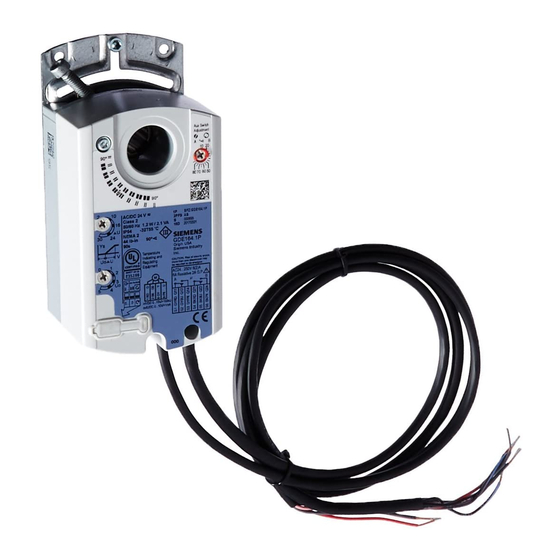
Figure 1. Parts of the GDE/GLB Rotary Actuator.
GLB131.1P
GLB132.1P
GLB136.1P
GLB161.1P
GLB163.1P
GLB164.1P
GLB166.1P
Personal injury/loss of life may
occur if you do not follow a
procedure as specified.
Equipment damage or loss of
data may occur if you do not
follow a procedure as
specified.
Installation Instructions
a. Actuator
b. Position indicator
c. Mounting bracket
c
d. Mounting screws
e. 4 mm hex key
f.
f
d
Instructions
WARNING:
Do not open the actuator.
NOTE:
Place the actuator on the damper shaft so
that the front of the actuator is accessible.
The label is on the front side.
1. Determine whether the damper blades will rotate
clockwise or counterclockwise to open. See
Figure 2.
2. If the blades will rotate counterclockwise, slide the
Manual Override switch to manual, and move the
adjustment lever to the right. Return the switch to
automatic. See Figure 9.
To mount a (modulating) GDE/GLB16x, set the Dual
In-line Package (DIP) switches to the required
positions.
1. To access the DIP switches, raise the tab on the
lower left side of the actuator. See Figure 2. The
factory setting is clockwise (middle switch), with a
direct-acting feedback signal (right switch).
2. Close the tab over the DIPswitches.
To mount a (3-positon) GDE/GLB13x for counter-
clockwise rotation, follow the Counterclockwise
Damper Rotation instructions located in the Wiring
Diagrams section when wiring the actuator to the
controller.
Document No. 129-367
September 1, 2003
Shaft insert for use with
3/8-inch (8-10 mm) shafts
Page 1 of 6
Advertisement

Related Manuals for Siemens GDE131.1U


Summary of Contents for Siemens GDE131.1U
- Page 1 NOTE: Place the actuator on the damper shaft so GDE131.1U GLB131.1P that the front of the actuator is accessible. GDE131.1U/B (24 pk) GLB132.1P The label is on the front side. GDE131.1P GLB136.1P 1. Determine whether the damper blades will rotate GDE131.1P/B (24 pk)
- Page 2 4 mm 60-90 lb-in (7-10 Nm) Torque Mounting GDE/GLB on 3/8-inch 8...10 mm shafts Figure 4. 3/8 Ø inch shaft, see Figure 1 Item f. Figure 7. Installing the Position Indicator (b). Page 2 of 6 Siemens Building Technologies, Inc.
- Page 3 † The long arm of the points to the setting. Manually turn the red ring of the B switch. The narrower tab on the ring points to the setting. See Figure 10. Siemens Building Technologies, Inc. Page 3 of 6...
- Page 4 6 (violet) and 7 (orange) wires at the controller. CAUTION: Do not wire different types of actuators (such as GBB or GIB actuators) in parallel with these Figure 13. models. Page 4 of 6 Siemens Building Technologies, Inc.
- Page 5 Black Switch A – N.O. Black Switch B – Common Black S2 S3 S5 S6 Switch B – N.C. Black Figure 15. 0 to 10V Modulating Control. Switch B – N.O. Black Siemens Building Technologies, Inc. Page 5 of 6...
- Page 6 Information in this publication is based on current specifications. The company reserves the right to make changes in specifications and models as design improvements are introduced. OpenAir is a trademark of Siemens Building Technologies, Inc. Other product or company names mentioned herein may be the trademarks of their respective owners.