Siemens SITRANS FUP1010 Operating Instructions Manual
Ultrasonic flowmeters ip67
Hide thumbs
Also See for SITRANS FUP1010:
- Operating instructions manual (208 pages) ,
- Quick start (2 pages) ,
- Quick start manual (46 pages)

Related Manuals for Siemens SITRANS FUP1010


Summary of Contents for Siemens SITRANS FUP1010
- Page 1 Ultrasonic flowmeters SITRANS FUP1010 IP67 7ME3510 Portable Flowmeter Operating Instructions - March 2012 SITRANS F Answers for industry.
- Page 3 ___________________ FUP1010 IP67 Portable Introduction ___________________ Safety notes ___________________ Description SITRANS F ___________________ Installing/mounting Ultrasonic Flowmeters ___________________ FUP1010 IP67 Portable Connecting ___________________ Commissioning Operating Instructions ___________________ Functions ___________________ Alarm, error, and system messages ___________________ Maintenance and service ___________________ Troubleshooting ___________________ Technical data ___________________ Appendix...
- Page 4 Note the following: WARNING Siemens products may only be used for the applications described in the catalog and in the relevant technical documentation. If products and components from other manufacturers are used, these must be recommended or approved by Siemens. Proper transport, storage, installation, assembly, commissioning, operation and maintenance are required to ensure that the products operate safely and without any problems.
-
Page 5: Table Of Contents
Table of contents Introduction..............................9 Preface............................9 Items supplied ..........................9 History ............................9 Further Information ........................10 Safety notes............................. 11 Laws and directives ........................11 Lithium batteries...........................12 Certificates ...........................12 Description............................... 13 FUP1010 features........................13 Applications..........................14 Theory of Operation ........................15 Installing/mounting........................... 21 Installation safety precautions......................21 Use according to specifications ....................21 Application Guidelines .........................22 AC Battery Charger........................22 Connecting .............................. - Page 6 Table of contents Empty Pipe Set ........................... 68 Installation Menus ........................72 Functions ..............................77 Selecting Flow Units........................77 Span Data ........................... 81 Logger Control ..........................83 Operation Adjust Menu Settings ....................86 Setting Relays ..........................89 Memory Control........................... 91 Analog Out Setup........................
- Page 7 Table of contents Appendix..............................155 Installation/Outline Drawings .....................155 Glossary ..............................157 Index..............................163 Tables Table 4- 1 Power Cord Codes........................24 Table 5- 1 Keypad Function Chart ........................35 Table 5- 2 Pipe Configuration Option List Definitions ...................39 Table 7- 1 Totalizer Modes ...........................78 Table 7- 2 Totalizer Controls (the "n"...
- Page 8 Table of contents Figure 5-2 Reflect Mount (Pipe shown from above in 12 o'clock position) ...........28 Figure 5-3 Direct Mount (Pipe shown from above in 12 o'clock position) .............29 Figure 5-4 Sensor Alignment (Horizontal Plane)...................30 Figure 5-5 Pipe Surface Preparation ......................31 Figure 5-6 Universal Sensor Label ........................32 Figure 5-7...
-
Page 9: Fup1010 Ip67 Portable Operating Instructions, 03/2012, A5E02951522-02
Table of contents Figure 10-1 Test Facilities Graph Screen......................127 Figure 10-2 Setting Digital Damping Factor ....................130 Figure 10-3 Setting the MinDamp Factor ......................131 Figure 10-4 Envelope Threshold Adjustment ....................133 FUP1010 IP67 Portable Operating Instructions, 03/2012, A5E02951522-02... - Page 10 Table of contents FUP1010 IP67 Portable Operating Instructions, 03/2012, A5E02951522-02...
-
Page 11: Introduction
Introduction Preface These instructions contain all the information you need for using the device. The instructions are aimed at persons mechanically installing the device, connecting it electronically, configuring the parameters and commissioning it as well as service and maintenance engineers. Note It is the responsibility of the customer that the instructions and directions provided in the manual are read, understood and followed by the relevant personnel before installing the... -
Page 12: Further Information
Product information on the Internet The Operating Instructions are available on the CD-ROM shipped with the device, and on the Internet on the Siemens homepage, where further information on the range of SITRANS F flowmeters may also be found: Product information on the internet (http://www.siemens.com/flow) -
Page 13: Safety Notes
Operating Instructions must be observed. CAUTION Material compatibility Siemens can provide assistance with the selection of sensor parts. However, the full responsibility for the selection rests with the customer and Siemens can take no responsibility for any failure due to material incompatibility. -
Page 14: Lithium Batteries
Do not expose contents to water. Certificates Certificates are posted on the Internet and on the documentation CD-ROM shipped with the device. See also Technical data (Page 141) Certificates on the Internet (http://www.siemens.com/processinstrumentation/certificates) FUP1010 IP67 Portable Operating Instructions, 03/2012, A5E02951522-02... -
Page 15: Description
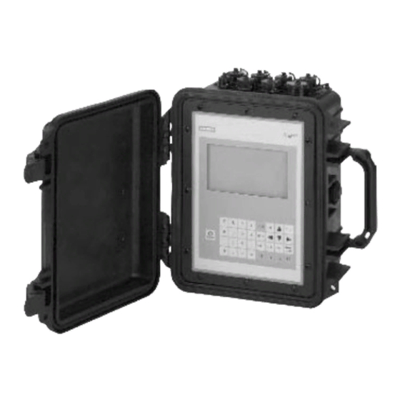
Description FUP1010 features Description The Siemens SITRANS FUP1010 Weatherproof IP67 Portable flow meters achieve highly accurate flow measurements using ultrasonic transit-time technology. The sensors are mounted on the outside of the pipe, preventing contact with the medium. This means no cavities or clogging by high paraffin liquids found in many hydrocarbon applications. -
Page 16: Applications
Description 3.2 Applications Channel Functions The system software allows simultaneous operation of one channel in the Transit-Time mode and the other in Reflexor mode. Transit-Time Mode All SITRANS F 1010 models use transit-time flow measurement technology varying only in functionality and environmental housing. Reflexor Mode The SITRANS F 1010 transit-time flow meter is highly resistant to the effects of liquid non- homogeneity caused by the inclusion of air or solid particulate. -
Page 17: Theory Of Operation
Description 3.3 Theory of Operation Typical Industries Serviced ● HVAC (Hotels, Airports, Government) ● Power Generation (Nuclear, Fossil, and Hydro) ● Chemical Processing ● Food and Pharmaceutical ● Aircraft Avionics and Ground Support ● Water and Wastewater ● Aerospace ● Automobile Manufacturing ●... - Page 18 Description 3.3 Theory of Operation ① Velocity of Sound ② Flow Vector ③ Pipe ID ④ WideBeam Sensors ∅° = sin (VOS / V Where: VOS = Velocity of sound in liquid phase = Phase velocity of sensor phase = 2 * ID / (VOS * cos ∅) ID = Pipe inside diameter = Transit time in liquid * DT / (2 * TL)
- Page 19 Description 3.3 Theory of Operation The Reynolds number is then computed as follows: where viscosity = cS = cP/density cS = kinematic viscosity cP = absolute viscosity The flow meter then uses this computation of Reynolds number to compensate the raw flow velocity for conditions of laminar or turbulent flow profile as defined by an internal Reynolds compensation table.
- Page 20 Description 3.3 Theory of Operation a) ρ = (141.5 *999.012) / (131.5 + API60) ● where:ρ = density at 60 F (Kg/m b) α / ρ / ρ 60 2 ● where K and K are coefficients of thermal expansion. c) ρ...
- Page 21 Description 3.3 Theory of Operation 2-Path 2-Path flow meters use two measurement channels to achieve a single output via a "virtual" third channel. The resultant data is the average of the two channels. Only clamp-on or in-line transit-time operation is allowed. Benefits include highest available precision and enhanced immunity to distorted flow profile conditions.
- Page 22 Description 3.3 Theory of Operation Flow Calibration Factor Normally, the flow stream is in line with the axis of the pipe. On this basis, the calibration factor of a clamp-on ultrasonic flow meter is proportional to the cosine of the beam angle relative to the pipe axis.
-
Page 23: Installing/Mounting
● Use the flow meter as support of external loads like pipes, etc. ● Change the flow meter in any way. For e.g. decomposition of material in connection with processing, welding and use of accessories and spare parts not approved by Siemens. Note If the flow meter is not used according to the specifications, the manufacturer cannot be held responsible for any resulting damage. -
Page 24: Application Guidelines
Installing/mounting 4.3 Application Guidelines Application Guidelines Basic Requirements ● Determine pipe material and dimensions. ● Avoid vertical pipes flowing in a downward direction. ● Avoid installation of sensors on the top and bottom of horizontal pipes, if possible. ● Select a location with the longest straight run of pipe. ●... -
Page 25: Figure 4-1 Power Adapter/Battery Charger
Installing/mounting 4.4 AC Battery Charger ① IEC 320 Power Inlet ② Connector ③ 0,9 meters minimum (3 ft) ④ NEMA 5 - 15P (see Power Cord table) ⑤ IEC 320 Plug (see Power Cord table) Figure 4-1 Power Adapter/Battery Charger FUP1010 IP67 Portable Operating Instructions, 03/2012, A5E02951522-02... -
Page 26: Table 4- 1 Power Cord Codes
Installing/mounting 4.4 AC Battery Charger Table 4- 1 Power Cord Codes Assembly P/N POWER CORD Plug Std. Rating 1015BCA-1 CEE 7/7 10A / 230VAC 1015BCC-1 A5 3112 10A / 250VAC 1015BCD-1 BS 1363 5A / 240VAC 1015BCJ-1 JIS 8303 12A / 125VAC 1015BCK-1 NEM 5-15P 10A / 120VAC... -
Page 27: Connecting
Connecting Transmitter Wiring 5.1.1 Forming the Internal Battery Battery Operation All portable systems include battery chargers that operate from an AC voltage source. We strongly recommend that you "form" and charge the battery before operating the system for the first time. The Charge Indicator LED A battery status indicator shows the status of its internal battery and charging circuits. - Page 28 Connecting 5.1 Transmitter Wiring To Produce a Charge/Discharge Cycle: 1. Press the ON keypad to turn the flow meter ON without connecting an external power source. Leave it ON until an automatic shutdown occurs. 2. Connect the AC charger (Page 27) and charge the internal battery with the meter power shut OFF.
-
Page 29: Connecting Ac Power Adapter/Charger
Connecting 5.1 Transmitter Wiring 5.1.2 Connecting AC Power Adapter/Charger Connecting the 1015BCK-1 (7ME39404PG00) Power Adapter/Charger 1. Connect the AC power cord to the AC cord input of the Power Adapter/Charger. 2. Plug the Power Adapter/Charger connector into the rear panel Auxiliary Power/Battery Charger input connector. -
Page 30: Sensor Wiring
Connecting 5.2 Sensor Wiring Sensor Wiring 5.2.1 Preliminary Installation Procedures Reflect and Direct Sensor Mounting Reflect and Direct mounting modes are supported for clamp-on sensors. The flow meter recommends a mounting mode after analyzing your pipe and liquid data entries. Note When installing sensors, do not key in the V/M (Version/Modification) label number as the Sensor Size. - Page 31 Connecting 5.2 Sensor Wiring Direct mount provides a shorter sonic beam path. This usually improves performance with sonically attenuative liquids or pipe materials. We recommend using Direct mount for plastic pipes. Compared to Direct mounting, Reflect mount requires almost double the amount of mounting length.
-
Page 32: Figure 5-4 Sensor Alignment (Horizontal Plane)
Siemens systems, or any type of ultrasonic equipment. You can run these cables through a common conduit ONLY if they originate at the same flow meter. -
Page 33: Sensor Identification And Selection
Connecting 5.2 Sensor Wiring Note Please note that the instructions show vertical mounting for clarity purposes only. Do not install sensors on the top of a pipe. ① Pipe ② Cleaned Areas Figure 5-5 Pipe Surface Preparation 4. Clean an area 13 mm (1/2-inch) on either side of the sensors. 5. - Page 34 Connecting 5.2 Sensor Wiring 1011 Universal series sensors and mounting frames have the following color codes for easy identification: ● Gold - size 'A' ● Blue - size 'B' ● Red - size 'C' ● Green - size 'D' ● Black - size 'E' Note Check to make sure that the sensors are a matched set with the same serial numbers and marked with an "A"...
- Page 35 Connecting 5.2 Sensor Wiring ① Hi Precision sensor model number ② Sensor size Figure 5-7 Hi Precision Sensor Label Sensor Selection Note The transmitter must be powered up before you can select a sensor model. Refer to Transmitter Wiring (Page 25). Before selecting sensors proceed to Setting the Parameters (Page 36) and perform the preliminary programming procedures.
-
Page 36: Navigating The Menu
Connecting 5.2 Sensor Wiring 5.2.3 Navigating the Menu Installation Menu Navigation The Installation Menu Chart is a multi-level structure divided into three columns from left to right Level A - lists the major menu categories. Level B - list the menu cells associated with Level A. You can enter data into Level B menu cells that are display parameters in a column at the right of the screen. -
Page 37: Table 5- 1 Keypad Function Chart
Connecting 5.2 Sensor Wiring Table 5- 1 Keypad Function Chart Keys Description MENU Press to activate the Installation Menu. ENTER Store numeric data, select from option lists, etc. Left / Right Arrows Menu navigation keys move cursor. Up / Down Arrows Same as <Left>... -
Page 38: Setting The Parameters
Connecting 5.2 Sensor Wiring 5.2.4 Setting the Parameters Select Language and Units Note Before creating a site select a language and then English or Metric units from the Meter Facilities menu. To select English or metric units: 1. In Meter Type Menu, scroll to [Meter Facilities] menu. Press <Right Arrow> and select preferred units. - Page 39 Connecting 5.2 Sensor Wiring ① Insert desired name (8 characters max.) Note To select letters: Press <Right Arrow> to cursor and then press <Up/Down Arrows> to select letters. Press <ENTER> when done. Note To select English or metric units: In Meter Type Menu, scroll to [Meter Facilities] menu. Press <Right Arrow>...
- Page 40 Connecting 5.2 Sensor Wiring 4. Pre-programmed Pipe Size and relevant pipe parameters will appear in menu cells. Press <Right Arrow> and scroll to desired pipe size. Press <ENTER>. Enter dimensions manually if pre-programmed dimensions do not match application. Note The DN sizes listed in the [Select Pipe Size] menu option list are referenced to DIN Table 2448.
-
Page 41: Table 5- 2 Pipe Configuration Option List Definitions
Connecting 5.2 Sensor Wiring ① Use this menu cell to enter the number of pipe diameters between the upstream configuration and the sensor installation. ② Use this menu cell to select the pipe configuration that most accurately represents the upstream pipe condition. 4. - Page 42 Connecting 5.2 Sensor Wiring 4. Press the <Right Arrow> to [Sensor Model]. Press <Right Arrow> and scroll to select the sensor model number on the sensor label. 5. The drop down menu lists the following sensor selections: – 1011 Universal –...
-
Page 43: Reflect Mount
Connecting 5.2 Sensor Wiring 5.2.5 Reflect Mount Reflect Mount using E-Z Clamp and Spacer Bar The EZ Clamp is a quick and easy way to securely mount sensors on any pipe. The spacer bar eliminates manual spacing measurements and provides rigidity for mounting the sensors while maintaining axial alignment. - Page 44 Connecting 5.2 Sensor Wiring Installation Procedure 1. After receiving the Number Index from the Installation Menu, prepare the pipe surface area where the sensors will be mounted. Check to ensure that you have a matched set of sensors. They both should have the same S/N number but marked with either an "A" or "B"...
-
Page 45: Figure 5-11 Sensor Mounting With E-Z Clamp And Spacer Bar
Connecting 5.2 Sensor Wiring ① ④ Adjusting Nut Sensor ② ⑤ Bit Snap E-Z Clamp Chain ③ ⑥ Spacer Bar Pipe Figure 5-11 Sensor Mounting with E-Z Clamp and Spacer Bar Note To surround larger pipes, link multiple lengths of chain together by mating the Bit Snap and "S"... -
Page 46: Figure 5-14 Connecting Sensors To Flow Meter
Connecting 5.2 Sensor Wiring 12. Tighten the adjusting nut until the chain is just snug around the pipe. Ensure that the chain is straight around the pipe and the sensor contacts the pipe at the white dot just under the front label. Ensure that there is equal space on either side of the dot between the edges of the sensor and pipe. -
Page 47: Direct Mount
Connecting 5.2 Sensor Wiring 5.2.6 Direct Mount Direct Mount - Installation with EZ Clamp and Spacing Guide The combination of EZ Clamp and spacer guide is the recommended way to mount Direct Mode sensors. This method ensures that sensors will align exactly 180° from each other and remain spaced the proper distance apart. -
Page 48: Figure 5-16 Ez Clamping Sensor To Pipe
Connecting 5.2 Sensor Wiring 4. Attach the EZ Clamp to the sensor under the spring clip. The adjusting nut knob should be pointing up and on the side opposite of the spacer bar. Unscrew the knob until it’s at the stop. ①... - Page 49 Connecting 5.2 Sensor Wiring 6. Place sensor at the center of the pipe in the middle of one of the areas you have cleaned. Ensure that the cable connector is facing away from where the other sensor will be placed. 7.
-
Page 50: Figure 5-19 Wrapping The Mylar Spacing Guide Around The Pipe (End View)
Connecting 5.2 Sensor Wiring ① ⑤ Sensor 1 Sensor Edge Line ② ⑥ Pipe Spacer Bar ③ ⑦ Place dot below white dot ④ ⑧ Sensor 2 Line ⑨ Mylar Spacing Guide 16. Wrap the Mylar spacing guide around the pipe so that the left edge is against the sensor edge mark (see "C"... -
Page 51: Figure 5-20 Finding The Halfway Distance
Connecting 5.2 Sensor Wiring 17. Realign left edge of the guide with the sensor edge mark. Line up both vertical edges of the guide and, ensuring that it is snug around the pipe, mark along the overlapping edge. 18. Remove Mylar spacing guide and lay it out on a flat surface. Either measure the exact distance half-way between the overlap edge and the mark at the overlap, or fold the guide from the overlap edge to the overlap mark and draw a line at the fold (halfway point). -
Page 52: Figure 5-22 Connecting Sensors To Flow Meter
Connecting 5.2 Sensor Wiring 23. Attached the EZ Clamp to the sensor under the spring clip. Unscrew the knob until it's at the stop. 24. Apply a continuous lengthwise 3mm (1/8-inch) bead of coupling compound across the center of the sensor emitting surface. 25. -
Page 53: 1012T Mounting Tracks
Connecting 5.2 Sensor Wiring 5.2.7 1012T Mounting Tracks Using 1012T Sensor Mounting Tracks The 1012TP and 1012THP Mounting Tracks provide a rigid mounting platform for Series 1011 Universal or high precision size A or B sensors. The mounting tracks service pipe sizes up to a maximum of 140 mm (5.00") outer diameter. -
Page 54: Figure 5-23 Reflect Mount With Model 1012Tp Mounting Track (Side View)
Connecting 5.2 Sensor Wiring 1. Perform all required menu steps up until the point where you respond to the [Install Complete?] prompt. 2. Make a note of the Number Index. Check to ensure that you have a matched set of sensors. -
Page 55: Figure 5-24 Reflect Mode Chain Loop (Front View)
Connecting 5.2 Sensor Wiring 4. Holding the track assembly in place, loop one of the roller chains under the pipe, pull it around and maintain tension while slipping a link over the tension screw hook. Tighten the tension screw enough to hold the assembly on the pipe, but still allow rotation. Repeat for the other roller chain. - Page 56 Connecting 5.2 Sensor Wiring Installing a 1012T Mounting Track in Direct Mode The Sensor Installation procedures show how the automatic selection of sensors, mounting mode and spacing method are established. Examine the figure below, which illustrates a typical [Install Sensor] menu screen. Note the automatic assignment of model numbers for the sensor and mounting track, plus the designation of the Number Index.
-
Page 57: Figure 5-25 Direct Mount 180° Opposed With Mounting Tracks
Connecting 5.2 Sensor Wiring Note Index pins are used as stops against each sensor inserted at the reference hole for one ⑩ sensor and the Number Index hole for the other sensor (see in figure below). ① ⑧ Tension Screw Pipe ②... - Page 58 Connecting 5.2 Sensor Wiring Track Assembly Installation 1. Perform all required menu programming steps up until the point where you respond to the [Install Complete?] prompt. 2. Make a note of the Number Index displayed in the [Install Sensor] menu. Check to ensure that you have a matched set of sensors.
-
Page 59: Figure 5-26 Direct Mount Roller Chain
Connecting 5.2 Sensor Wiring ① ⑤ Chain Tension Screw Centering Pin ② ⑥ Chain Hook Sensor 1 and Clamping Screw ③ ⑦ Track Rail Assembly 1 Pipe ④ ⑧ Track Rail Assembly 2 Sensor 2 Figure 5-26 Direct Mount Roller Chain Note For a vertical pipe installation, use a tie, tape or bungee cord to hold the two tracks in place while chaining. -
Page 60: Figure 5-27 Wrapping The Mylar Spacing Guide Around Pipe (End View)
Connecting 5.2 Sensor Wiring Positioning Track Assemblies 1. Wrap a length of the Mylar spacing guide around the pipe and against the end of the track assemblies. Ensure that the spacer guide edges on both sides align. Arrange so that one end overlaps the other by at least 8 cm (3 inches). Trim to fit if necessary, but in order to keep the end square, be sure not to trim at the overlapping end. -
Page 61: Figure 5-29 Track Rail Alignment
Connecting 5.2 Sensor Wiring 3. Use the edge of the Spacer Guide as a stop for both tracks to keep them parallel. Adjust tracks as necessary. ① Align tracks with Spacer Guide edge ② Mylar Spacer Guide ③ Halfway distance of Spacer Guide Figure 5-29 Track Rail Alignment 4. -
Page 62: Figure 5-30 Ref And Number Index Pin Locations
Connecting 5.2 Sensor Wiring Sensor Installation 1. Insert an index pin into the REF hole of the track marked "Reflect Mode Spacing." 2. Take one of the sensors and insert it between the track rails and to the left of the index pin with the cable connector pointing away from the pin. -
Page 63: Zero Flow Adjust Menu
"match" of the electronics, cables and ultrasonic sensors. Consequently some flow offset (or zero offset) may be present in any installation. To eliminate this residual zero offset Siemens has developed several different methods to insure proper zero flow compensation. The following paragraphs describe each method and when they should be used. - Page 64 Connecting 5.3 Zero Flow Adjust Menu Actual Zero The Actual Zero function simply averages the indicated "zero flow" readings (over a user defined time period) then stores this average value in memory. Under normal operation the indicated flow reading is zero compensated by simply subtracting this memorized value from the uncompensated flow reading.
- Page 65 Connecting 5.3 Zero Flow Adjust Menu To invoke Actual Zero: 1. Access the [Zero Flow Adjust] option list by pressing <Right Arrow>. 2. Press <ENTER>. A pop-up window prompts you to set the current flow rate (in selected rate units) to equal zero (0.000). Note If a flow offset is desired (i.e., to test analog outputs) then press <Right Arrow>...
- Page 66 Connecting 5.3 Zero Flow Adjust Menu This completes the ReversaMatic procedure. The system’s zero accuracy will be very close to that obtainable using the Actual Zero method, providing flow remained constant during this procedure. CAUTION A caution on the use of upper and lower flow limits (used to prevent flow mis-registration) prior to using the Reversal Zero technique (ReversaMatic): If the negative flow rate that the flow meter reads in the step during which the sensors are reversed is more negative than the lower flow limit, the meter will re-register positive and the Reversal Zero cycle will thus...
- Page 67 Connecting 5.3 Zero Flow Adjust Menu To disable the ZeroMatic function: 1. Select the [Install Sensor] menu cell from the [Dual Path Flow] menu. 2. Scroll down to the [Zero Flow Adjust] menu cell by pressing <Up/Down Arrow>. Note The highlighted [ZeroMatic] menu item is the only indication that ZeroMatic is functioning. 3.
- Page 68 Connecting 5.3 Zero Flow Adjust Menu FUP1010 IP67 Portable Operating Instructions, 03/2012, A5E02951522-02...
-
Page 69: Commissioning
Power Adapter / Battery Charger. 1. Apply power. 2. Within 10 seconds of power-up the main display will become active and a typical Siemens graphic will appear briefly. The screen also identifies the software version of the unit as shown below. ①... -
Page 70: Empty Pipe Set
Commissioning 6.3 Empty Pipe Set Final Setup 1. Press <MENU> key once to display the main menu. 2. Press the <Right Arrow> twice. 3. Scroll down to [Install Complete]. Press the <Right Arrow> and select [Install]. Press <ENTER>. The flow meter will go through its drives. 4. - Page 71 Commissioning 6.3 Empty Pipe Set Actual MTY Command If application conditions allow you to empty and refill the pipe, then you may choose to perform the Actual Empty procedure; however, it is not required to do so. Note IMPORTANT NEVER perform the Actual MTY procedure if the pipe can not be emptied. To use the Actual MTY command: 1.
- Page 72 Commissioning 6.3 Empty Pipe Set Using the MTYmatic command You can repeat MTYmatic (performed during the Initial Makeup) to correct an inaccurate Actual MTY setting if conditions do not allow you to repeat the Actual Empty procedure. Note IMPORTANT Only use the MTYmatic procedure when the pipe is full. To start MTYmatic: 1.
- Page 73 Commissioning 6.3 Empty Pipe Set 4. Press <ENTER>. The current empty threshold number appears in a pop-up window. 5. Use the numeric keys to type a new Set Empty number. 6. To store the Set Empty number press <ENTER> FUP1010 IP67 Portable Operating Instructions, 03/2012, A5E02951522-02...
-
Page 74: Installation Menus
Commissioning 6.4 Installation Menus Installation Menus FUP1010 Installation Menu Chart Level A Level B Level C Level D Level E Level F Level G Level H Meter Type 2-Channel Channel 1/2 FastStart Pick Pipe Enter From List Flow Setup Class Clamp-on Dual Path Reflexor... - Page 75 Commissioning 6.4 Installation Menus Level A Level B Level C Level D Level E Level F Level G Level H Density S.G. Numeric Entry Temp. Range Enter From List Pipe Config Enter From List Anomaly Diams Numeric Entry Install Sensor Sensor Model Enter From List Sensor Size Enter From List...
- Page 76 Commissioning 6.4 Installation Menus Level A Level B Level C Level D Level E Level F Level G Level H Logger Data Enter From List Logger Interval Enter From List Logger Events Enter From List Display Logger Enter From List I/O Data Analog Out Setup Enter From List Control...
- Page 77 Commissioning 6.4 Installation Menus Level A Level B Level C Level D Level E Level F Level G Level H Trim Vo1 Operate / Trim @ Trim Vo2 Operate / Trim @ Trim Pgen1 Operate / Trim @ 1Khz Trim Pgen2 Operate / Trim @ 1Khz...
- Page 78 Commissioning 6.4 Installation Menus Level A Level B Level C Level D Level E Level F Level G Level H System Time View mm.dd.yy.hh. Only mm.ss Language Enter From List FUP1010 IP67 Portable Operating Instructions, 03/2012, A5E02951522-02...
-
Page 79: Functions
Functions Selecting Flow Units Selecting Flow Units The [Flow/Total Units] menu is available after selecting a meter type and measurement channel. Use the [Flow/Total Units] menu to select volumetric flow units and an associated time base for the flow rate and total outputs. After making your selections, a view-only menu cell shows the resultant scaling. -
Page 80: Table 7- 1 Totalizer Modes
Functions 7.1 Selecting Flow Units 5. Press the <Right Arrow> to select the option list and use the <Up/Down Arrows> to select the desired units. 6. Press <ENTER> to store selection. Totalizer Modes The Totalizer function operates in any of the modes listed below: Table 7- 1 Totalizer Modes Mode... - Page 81 Functions 7.1 Selecting Flow Units 4. Scroll down to the [Totalizer Mode] menu and press the <Right Arrow> to select the Totalizer Mode option list. 5. Press the <Up/Down Arrows> to select the desired mode. 6. Press <ENTER> to store selection. Totalizer Mode Controls From the RS-232 serial port all of the Totalizer commands listed below can be executed using PC keyboard function keys via VT100 terminal key emulation.
-
Page 82: Table 7- 2 Totalizer Controls (The "N" In
Functions 7.1 Selecting Flow Units 8. At the Terminal screen, press <ENTER> and the Data Display mode appears. 9. If not, to enter the Data Display mode type MENU and then press <Ctrl L>. Table 7- 2 Totalizer Controls (the "n" in <Fn> = channel number)* PC # Command Description...= Channel Number) -
Page 83: Span Data
Functions 7.2 Span Data Span Data The [Span Data] menu allows you to set 0% and 100% output limits for volumetric flow (Vfo), absolute flow (Vfab) and sonic velocity (Vs). Each menu cell shows appropriate rate units and time base. If you change flow rate units after spanning the system, the computer automatically updates the output data setup to reflect the change. - Page 84 Functions 7.2 Span Data 3. Highlight [Span Data] and press the <Right Arrow>. 4. Highlight [Max Flow] and press <Right Arrow> to. Input 100% flow rate numeric data for 20mA. Press <ENTER> to store data. 5. Scroll down to [Min Flow].Press <Right Arrow> to input 0% flow rate numeric data for 4mA.
-
Page 85: Logger Control
Functions 7.3 Logger Control Logger Control Logger Control Menu The Logger Control menu in the [Meter Facilities] menu provides the Logger controls for the flow meter measurement channels and paths. It allows the user to select data items/alarm events, a logging interval and a destination for Logger reports. While the Logger Setup menu is measurement channel/path specific, this Logger Control menu provides global control functions. - Page 86 Functions 7.3 Logger Control Display Logger This menu cell allows you to send the Logger contents to the display screen. This command is effective only after a successful install. You can set the report to scroll on the screen with or without line-wrap.
- Page 87 Functions 7.3 Logger Control 4. To transmit Logger contents to external device via the serial port press <ENTER>. 5. To stop printout press <Left Arrow>. Circular Memory In its default mode, the Logger collects data until its memory becomes full. At that time the flow meter suspends datalogging and cannot resume until the Logger memory is cleared (see Clear Logger command).
-
Page 88: Operation Adjust Menu Settings
Functions 7.4 Operation Adjust Menu Settings Clearing Logger Memory 1. To access the [Clear Logger] option list press <Right Arrow>. 2. Move the cursor to [Yes] by pressing <Up/Down Arrow>. 3. To clear the memory press <ENTER>. Operation Adjust Menu Settings Introduction The [Operation Adjust] menu becomes available after picking a meter type and measurement channel. - Page 89 Functions 7.4 Operation Adjust Menu Settings 4. Use the numeric keys to type the new Time Average setting. 5. To register the new value press <ENTER>. Setting SmartSlew: 1. From the [Dual Path Flow] menu scroll to the [Operation Adjust] menu and press <Right Arrow>.
- Page 90 Functions 7.4 Operation Adjust Menu Settings Memory/Fault Set Certain situations will interrupt data production (e.g., an empty pipe or excessive aeration). Use Memory/Fault Set to select the flow meter response to such an interruption. The Fault setting (default) will zero the flow rate output and declare an alarm on a flow display screen, Datalogger report and an assigned relay output.
-
Page 91: Setting Relays
Functions 7.5 Setting Relays 1. FAULT – When selected the system will declare the Reflexor channel to be in Fault and the flow meter will indicate "F" on the display screen. Note that when a new Reflexor channel is created the [Fault] option is the default mode. Also note that the sum (or difference) channel will also be declared to be in Fault. - Page 92 Functions 7.5 Setting Relays Reverse Flow Flow is in negative direction. BatchTot Batch/Sample total advances. Interface Liquid interface set point exceeded. Pos Total Positive total volume advances 1 digit. Neg Total Negative total volume advances 1 digit. Assigning functions to Relay 1: 1.
-
Page 93: Memory Control
Functions 7.6 Memory Control Memory Control Introduction Memory Control is a reference menu that shows the amount of bytes of data memory left. The data memory capacity depends on the number and complexity of the site setups stored in memory and the size of the current Datalogger file. The [Memory Control] menu is located in the [Meter Facilities] menu. -
Page 94: Analog Out Setup
Functions 7.7 Analog Out Setup Analog Out Setup Analog Out Setup The flowmeter provides current, voltage and pulse-rate analog outputs. The [Analog Out Setup] menu allows you to assign data functions for these signals. The transmitter terminal strip contains the analog output terminals. Table 7- 6 Analog Outputs Io (Isolated Current) - Page 95 Functions 7.7 Analog Out Setup Io Output Functions This output also provides an industry-standard fault indication by dropping to 2mA if assigned to flow rate and under fault conditions. Assigning a function to the current output: 1. From the [Dual Path Flow] menu scroll to [I/O Data Control]. 2.
-
Page 96: Analog Input Setup
Functions 7.8 Analog Input Setup Vo Output Functions The Vo analog output is a 0-10 VDC signal that varies linearly in relation to a selected function. Assigning a function to the voltage output: 1. From the [Analog Out Setup] menu, press <Right Arrow] to access the [Vo1] option list. 2. - Page 97 Functions 7.8 Analog Input Setup For example, when using the analog input Aux function, assigned numeric variables for temperature monitoring might be spanned as follows: 4mA=1 (0°C / 32°F) and 20mA=100 (100°C / 212°F). Temperature data sent to the Aux 1 input port will feed through the flow meter and report the scaling data to the Datalogger.
- Page 98 Functions 7.8 Analog Input Setup Setting the Analog Current Input The DC current input port must be enabled first. From the [Analog Inp Setup] menu proceed as follows: 1. Access the [Iin1] option list by pressing the <Right Arrow> twice. 2.
-
Page 99: Analog Output Trim
Functions 7.9 Analog Output Trim 3. To enable numeric entry, press the <Right Arrow>. Type a numeric value corresponding to a 4mA input signal. 4. To store the data press <ENTER>. This moves the cursor to [20 mA]. 5. To enable numeric entry, press the <Right Arrow>. Type the numeric value corresponding to a 20mA input signal. - Page 100 Functions 7.9 Analog Output Trim Current Output Trim (Io1 & Io2) Note Can be trimmed to within .005mA of nominal. To calculate a current output: 1. Set up the ammeter and then connect it to the supply and return terminals of the current output under test.
- Page 101 Functions 7.9 Analog Output Trim To calculate a voltage output: 1. Set up the multi-meter to read volts, then connect it to the supply and return terminals of the voltage output under test. 2. Move the highlight to the port to be tested by pressing <Up/Down Arrow>, press <Right Arrow>, then press <Down Arrow>...
-
Page 102: Rtd Calibration
The RTD Calibrate Menu appears on all SITRANS F 1010 models. Use this menu to calibrate Temperature Sensors to an external standard. It is important to note that Siemens RTD temperature sensors are factory-calibrated for high accuracy. We recommend that before deciding to perform the calibration, check the current RTD reading in the [Diagnostics/Liquid Data] menu. -
Page 103: Table 7- 9 Rtd Calibrate Menu Structure
Functions 7.10 RTD Calibration Table 7- 9 RTD Calibrate Menu Structure RTD Calibrate RTD 1 Factory User Cal RTD 2 Factory User Cal RTD Calibration by Entry Data The [RTD Calibrate] menu allows you to adjust the intrinsic RTD reading to match an external reference thermometer by directly entering its reading. - Page 104 Ice Bath RTD Calibration Use distilled deionized water and ice mixture at 0°C (32°F) equilibrium for an ice bath. Ensure temperature with a reference thermometer. Siemens can not assume responsibility for the incorrect design, construction or operation of an Ice Bath.
-
Page 105: Reflexor
Functions 7.11 Reflexor 7.11 Reflexor Reflexor is one of the operating modes available on certain SITRANS F 1010 models. The Reflexor operating mode utilizes Doppler flow detection along with digital signal processing techniques to successfully measure flow under conditions that may not be suitable for transit-time flow measurement. - Page 106 Functions 7.11 Reflexor Selecting Sensor Mounting Location Select a sensor mounting location that has a fully developed flow profile. Do not locate the sensor so that sonic energy enters a region that is not representative of the flow velocities at the measuring location.
-
Page 107: Table 7- 10 Inline Metal And Plastic Pipe Cable Connections
Functions 7.11 Reflexor Mounting Sensors Two mounting configurations are available in the Reflexor Mode: ● Adjacent mounting locates the two sensors alongside each other using a single mounting chain or strap. ● In-Line mounting locates the two sensors axially along the pipe using two mounting chains or straps. - Page 108 Functions 7.11 Reflexor ① ② Connect to DN on flow meter for metal Connect to UP on flow meter for metal pipe (Receive) / Connect to UP on flow pipe (Receive) / Connect to DN on flow meter for plastic pipe (Transmit) meter for plastic pipe (Transmit) ③...
- Page 109 Functions 7.11 Reflexor Installing Reflexor Operating Mode 1. From the [Meter Type] menu press the <Right Arrow>, select the desired channel setup and press <ENTER>. 2. Press the <Right Arrow>, scroll to [Reflexor] and press <ENTER>. 3. At the [Channel Setup] menu press the <Right Arrow>. 4.
- Page 110 Functions 7.11 Reflexor 4. In the [Install Sensor] menu, scroll down to [Flow Range], press the <Right Arrow> and select the lowest flow range rate available that is at least two times higher than the maximum flow expected at this application. 5.
-
Page 111: Figure 7-4 Spectra Graph Display Screen
Functions 7.11 Reflexor Selecting the Spectra Graph Display 1. In the [Install Sensor] menu scroll to [Spectra Graph] and press the <Right Arrow>. 2. Press the <Down Arrow>to select [Yes] and press <ENTER>. The Spectra Graph display shows the results of the Fast Fourier Transform (FFT) performed by the flow meter. -
Page 112: Table 7- 11 Cursor Definitions
Functions 7.11 Reflexor The reported flow rate is the mean value of the included Spectra Graph bars. It is computed by excluding signals that are lower (to the left of) than the Low Limit Cursor or higher (to the right of) than the High Flow Cursor or lower (under) than the Noise Cursor. Spectra Graph Cursor Use Table 7- 11 Cursor Definitions... - Page 113 Functions 7.11 Reflexor 3. Adjust the Noise Level cursor, if required, by pressing the <+> key to increase or <-> key to decrease. Note A delay in response to all keys will occur. This is due to the longer periodic sampling of the keyboard by the processor while performing FFT’s.
-
Page 114: Table 7- 12 Diagnostic Data
Functions 7.11 Reflexor Table 7- 12 Diagnostic Data Application Information Function / Explanation Low Limit High Pass Filter Setting High Limit Low Pass Filter Setting Noise Level Set Noise Filter Setting Doppler Frequency (Hz) Average FFT Frequency % Deviation The width of Spectra is used to determine beam penetration and calibration. - Page 115 Functions 7.11 Reflexor Display of "F" at No-Flow conditions It is normal for the digital display to show an "F" for the no flow condition since the lack of Spectra information during no flow is the same as a fault condition. Note Selecting the [Operation Adjust] menu cell [Zero/Fault Set] allows the option of indicating Zero Flow rather than a Fault.
- Page 116 Functions 7.11 Reflexor FUP1010 IP67 Portable Operating Instructions, 03/2012, A5E02951522-02...
-
Page 117: Alarm, Error, And System Messages
Alarm, error, and system messages Alarm Letter Codes Alarm Letter Codes The following alarm codes appear on the main display of the flow meter. Table 8- 1 Alarm Codes and Descriptions Letter Codes Alarm Code Description SPACE Spacing Sensor spacing may need adjustment EMPTY Empty Pipe is empty... - Page 118 Alarm, error, and system messages 8.1 Alarm Letter Codes 68.10 112.38 30.0 -30.0 9/26 12:45 ① Alarm Codes FUP1010 IP67 Portable Operating Instructions, 03/2012, A5E02951522-02...
-
Page 119: Maintenance And Service
Service & Support on the Internet In addition to our documentation, we offer a comprehensive knowledge base online on the Internet at: Service and support (http://www.siemens.com/automation/service&support) There you will find: ● The latest product information, FAQs, downloads, tips and tricks. -
Page 120: Replacing The Battery
Maintenance and service 9.3 Replacing the battery Additional Support Please contact your local Siemens representative and offices if you have additional questions about the device. Find your local contact partner at: http://www.automation.siemens.com/partner See also Local contact person (http://www.automation.siemens.com/partner) Replacing the battery The internal battery pack used with SITRANS F 1010 portable flow meters may be removed and replaced when needed. -
Page 121: Figure 9-1 Faceplate Removal
Maintenance and service 9.3 Replacing the battery ① Top cover release latch ② Faceplate screws (12) ③ Pry open faceplate here Figure 9-1 Faceplate Removal CAUTION When lifting faceplate make sure not to damage wire harnesses. FUP1010 IP67 Portable Operating Instructions, 03/2012, A5E02951522-02... -
Page 122: Figure 9-2 Battery Cover Removal
Maintenance and service 9.3 Replacing the battery 5. Pry up faceplate and gently lift upwards. Tilt faceplate back and rest it securely so that the inside of the flow meter is accessible but that there is no pressure on the wiring harnesses. -
Page 123: Battery Disposal
In accordance with EU directive 2006/66/EC, batteries are not to be disposed of using municipal waste disposal services. Waste industrial batteries are accepted back by Siemens or by the local Siemens representative. Please talk to your local Siemens contact (http://www.siemens.com/processinstrumentation/contacts) or follow the return procedures (Page 122) of Siemens Flow Instruments. -
Page 124: Disposal
Required forms ● Delivery Note ● Cover Note for Return Delivery with the following information Cover note (http://support.automation.siemens.com/WW/view/en/16604370) – product (ordering number) – number of devices or spare parts returned – reason for the return ● Declaration of Decontamination Declaration of Decontamination (http://pia.khe.siemens.com/efiles/feldg/files/Service/declaration_of_decontamination_en. -
Page 125: Troubleshooting
The following is list of troubleshooting tips and messages that you may encounter. They include explanations and, in some cases, a recommended action. If a problem seems unsolvable, contact your local Siemens office or regional Ultrasonic Flow Representative for expert help at: http://www.automation.siemens.com/partner (http://www.automation.siemens.com/partner). - Page 126 Troubleshooting 10.1 Troubleshooting Error or Message Probable Cause Solution Re-space Index The measured liquid sonic velocity (Vs) is Ensure proper pipe dimensions and/or Liquid more than +/- 25% of the average Vs range. data entries are correct. Properly enter correct Sensor Size into the ...
-
Page 127: F4 Reset Procedure
10.2 F4 Reset Procedure Note If you receive a Detection Fault message, it is strongly recommended that the Technical Service Department (http://www.automation.siemens.com/partner) be contacted. 10.2 F4 Reset Procedure You may encounter an operating problem that blocks access to the Diagnostics Menu, or the flow meter may operate erratically after exposure to a power transient or some other traumatic event. -
Page 128: Test Facilities Graph Screen
Troubleshooting 10.3 Test Facilities Graph Screen Clearing All Saved Data 1. Turn off power (if it is currently on). 2. Press <F4> and keep it pressed while you turn on power. The prompt: [Clr Active Memory? No] appears at the top of the screen. Press the <Down Arrow>. Note that the prompt switches to [Clr Saved Data? No]. - Page 129 Troubleshooting 10.3 Test Facilities Graph Screen Figure 10-1 Test Facilities Graph Screen Entering the Diagnostic Graph Screen Before you can view the Diagnostic Graph Screen the flow channel must first be properly installed and operating in a non-empty condition. If a previously installed channel is in a "Fault"...
- Page 130 Troubleshooting 10.3 Test Facilities Graph Screen Time Base Control The digitized receive signal can be moved either to the left or right on the screen by pressing the <Left> or <Right> keypad arrows. The direction of the arrow actually represents the direction in which the Receive "window"...
- Page 131 Troubleshooting 10.3 Test Facilities Graph Screen [MinDamp #] Command Pressing the <1> key will cause [MinDamp #] to appear on the command line at the lower left-hand corner of the screen. The number listed to the right of the command code represents the exponent in the meter exponential averaging routine, where the larger the number the greater the digital averaging.
-
Page 132: Figure 10-2 Setting Digital Damping Factor
Troubleshooting 10.3 Test Facilities Graph Screen To activate the Test Facilities Graph Screen: 1. In the main menu, scroll to the [Diagnostic Data] menu and select [Test Facilities]. 2. Scroll down to [Graph], press the <Right Arrow> and highlight [Yes]. Press <ENTER> to select. -
Page 133: Figure 10-3 Setting The Mindamp Factor
Troubleshooting 10.3 Test Facilities Graph Screen To INCREASE the Digital Damping: 1. Press the <1> key while viewing the Test Facilities Graph Screen as shown above. The damping control [MinDamp #] will appear on the command line at the lower left-hand corner of the screen. - Page 134 Troubleshooting 10.3 Test Facilities Graph Screen Transit Time Adjustment: (Hot Key 3) Observe the short vertical marker at the beginning of the receive signal in the Graph Screen above. This line represents the position in time (Tn) where the flow meter perceives the arrival of the ultrasonic signal.
- Page 135 Troubleshooting 10.3 Test Facilities Graph Screen Envelope Threshold Adjustment: (Hot Key 5 & 6) Pressing the <=> key causes the graph to toggle between the default signal waveform screen and the signal envelope screen (see example below). This envelope screen can aid in the diagnosis of Tn errors caused by unusual receive waveform distortion.
-
Page 136: Table 10- 2 Description Of Graph Screen Text Display Parameters
Troubleshooting 10.3 Test Facilities Graph Screen Signal Masking Function: (Hot Key 7) Under conditions of extremely low signal amplitude, a noise spike associated with the flow meter receive signal window may be present on the extreme left side of the graph display. If this spike is large enough it may interfere with the signal detection routines. -
Page 137: Table 10- 3 Hot Key Summary
Troubleshooting 10.3 Test Facilities Graph Screen Table 10- 3 Hot Key Summary Command Line Description <+> Expands (magnifies) waveform to view more detail. <-> Contracts waveform to view more of the waveform. <Left Arrow> Shifts receive window to the left (waveform to the right). -
Page 138: Site Setup Data
Troubleshooting 10.4 Site Setup Data 10.4 Site Setup Data This menu provides data pertaining to sensor characteristics and operation. Some menu items are for technical support interpretation only. Table 10- 4 Site Setup Menu Items fx Drive Current Transmit drive code selected during Initial Makeup. - Page 139 Troubleshooting 10.4 Site Setup Data [HF] Menu Item The flow meter includes a Diagnostics Menu item that permits the entry of a flow registration correction parameter labeled [HF]. This "HF" parameter is the input for a proprietary algorithm that automatically compensates for signal beam blowing, thereby extending the upper flow limit of the flow meter.
- Page 140 Troubleshooting 10.4 Site Setup Data Manual Adjustment Procedure 1. In the [Site Setup Data] Menu, press the <Down Arrow> and scroll to the [HF] menu cell. Press the <Right Arrow> and a pop-up [Manual] prompt will appear as shown below. Note Press the <Up/Down Arrow>...
- Page 141 Troubleshooting 10.4 Site Setup Data Automatic Adjustment Procedure 1. In the [Site Setup Data] Menu, press the <Down Arrow> and scroll to the [HF] menu cell. Press the <Right Arrow> and a pop-up [Manual] prompt will appear. 2. Press the <Up or Down Arrow> to select [Automatic] then press <ENTER>. 3.
- Page 142 Troubleshooting 10.4 Site Setup Data Note The value shown in the [Automatic] pop-up prompt can not be changed and is for user information only. 5. If you decide not to use the [Automatic] selection, press any key other than <ENTER> to abort the operation.
-
Page 143: Technical Data
Technical data 11.1 Technical Data Temperature Range Degree of Protection Operating: -18°C to 60°C (0°F to 140°F) IP67 (weather proof)) Storage: -20°C to 60°C (-4°F to 140°F) Performance The following specifications apply under standard conditions (i.e., measurements taken on a straight run of 15 diameters upstream and 5 diameters downstream;... - Page 144 Technical data 11.1 Technical Data FUP1010 IP67 Portable Operating Instructions, 03/2012, A5E02951522-02...
-
Page 145: Appendix
In order to ensure that the ordering data you are using is not outdated, the latest ordering data is always available on the Internet: Catalog process instrumentation (http://www.siemens.com/processinstrumentation/catalogs) See also Process instrumentation catalog (http://www.siemens.com/processinstrumentation/catalogs) I/O Connections and Wiring Terminal Block Wiring - FUP1010 IP67 Battery Powered 2 Channel/2 Path Weatherproof Flow Meter Wiring... -
Page 146: Table A- 2 2 Channel/2 Path Input/Output Terminal Block Wiring
Appendix A.2 I/O Connections and Wiring Table A- 2 2 Channel/2 Path Input/Output Terminal Block Wiring Pin# Signal Function Description Signal Ground Return For Signals No Connection Logic Out 1 Logic Level State (HIGH=5 to 3 VDC; LOW= 1 to 0 VDC) No Connection Logic Out 2 Logic Level State (HIGH=5 to 3 VDC;... -
Page 147: Site Setup For Sitrans F
Appendix A.3 Site Setup For SITRANS F Site Setup For SITRANS F How to use the Windows HyperTerminal Program Windows provides a communication program called HyperTerminal, which is ideal for interfacing your computer with the flow meter. The following typical example explains how to set up HyperTerminal. - Page 148 Appendix A.3 Site Setup For SITRANS F 7. Left-click the [Settings] tab. Expand the [Emulation] box by left-clicking the <Down Arrow> on the right-hand side. Drag the highlight down to [VT-100] and then left-click to select it (as shown below). 8.
- Page 149 Appendix A.3 Site Setup For SITRANS F ● Drag to Accessories. Drag to [Communications], and click. ● Double-click the icon you selected for the connection. Note For easier access, create a shortcut to the connect icon from your desktop. Right-click on the icon to open its dialog box.
- Page 150 Appendix A.3 Site Setup For SITRANS F Data Display Mode After you complete the installation, you can toggle between Installation Menu mode to Data Display mode. This is the same as using the <MENU> key on the transmitter keypad. The PC keyboard equivalent to the <MENU>...
- Page 151 Appendix A.3 Site Setup For SITRANS F SITRANS F 1010 Keypad PC Keyboard Description <Up Arrow> <Up Arrow> Move up 1 menu cell (or Flow Display screen) <Down Arrow> <Down Arrow> Move down 1 menu cell (or Flow Display screen) <Right Arrow>...
- Page 152 Appendix A.3 Site Setup For SITRANS F SITE "n" Invokes a site download for channel "n", where "n" = the Channel # (1, 2, 3, 4, etc.). DP "n" Commands the flow meter to download the digitized receive signal data for Channel or Path "n".
- Page 153 Appendix A.3 Site Setup For SITRANS F Closing the Terminal or HyperTerminal Program You may now close the Terminal program. The file(s) you have downloaded are now saved in the location you selected. You may now import the file you have saved into the appropriate program (i.e., MS Word for site data, or MS Excel for Datalogger or Wave shape data for graphing or analysis).
-
Page 154: Flowrate Calibration And Calibration Tables
Appendix A.4 Flowrate Calibration and Calibration Tables 3. Press the <Right Arrow> and then the <Down Arrow> to switch the option list to: [Clr Saved Data? Yes]. 4. Press <ENTER> to clear all Saved Site Data, Datalogger Data, User created Pipe Data and Sensor Data. - Page 155 Appendix A.4 Flowrate Calibration and Calibration Tables Kc Factor To obtain the Kc factor, compare flow total data taken simultaneously from the flow meter and a reference meter whose accuracy meets the required standard. Allow both meters to accumulate flow total data long enough to average out any differences due to flow fluctuation between the two meter locations.
- Page 156 Appendix A.4 Flowrate Calibration and Calibration Tables Calibration Tables 1 through 3 SITRANS F 1010 instruments offer a unique methodology by which a particular flow response of an instrument may be linearized or optimized by tabulating the results of a series of calibration exercises or collected batch data points.
-
Page 157: Appendix
Appendix Installation/Outline Drawings The following are the installation and outline drawings for the SITRANS FUP1010 portable flow meter. 1010WP-7 - Installation Drawing, Single Channel Weather Proof Portable Flow Meter 1010WDP-7 - Installation Drawing, Dual-Channel Weather Proof Portable Flow Meter 1010WP-8 - Outline Dimensions, Single Channel Weather Proof Portable Flow Meter... - Page 158 Appendix B.1 Installation/Outline Drawings 990TDMVH-7B - Installation Drawing, 990 Series Transducer Assembly, Very High Temp., Direct Mode 990TRMVH-7A - Installation Drawing, 990 Series Transducers & Tracks, Very High Temp., Reflect Mode 990TRMVH-7B - Installation Drawing, 990 Series Transducers Assembly, Very High Temp., Reflect Mode 191P1-7 - Installation Drawing, 191P1 Portable Transducer 191P1-8 - Outline Dimensions, 191P1 Portable Transducer...
- Page 201 Siemens Industry, Inc. Industry Automation Division CoC Ultrasonic Flow Hauppauge, New York 11788 USA Web: www.usa.siemens.com Sonic Velocity Relative to Temperature of Pure Water Temperature Velocity Temperature Velocity Temperature Velocity °F °C °F °C °F °C -17.8 1292.45 100.0 37.8 1525.03...
- Page 203 Glossary Active Memory Section of RAM allocated for active site parameters (all current values). The flow meter receives site-specific operating instructions from Active Memory. Alphanumeric Field An 8-character data entry field that allows you to specify a Site Name or a Security code. Arrow Keys Use the <Up, Down, Left and Right>...
- Page 204 Glossary ENTER Key Use the <ENTER> key to store a current numeric value or option list item. Flow Meter Refers to the flow meter itself (the transmitter and sensors combined). Graphic Screen Refers to the integral LCD display screen. Initial Makeup An internal process performed during installation, where the flow meter acquires its receive signal and enhances other parameters for optimal operation at a site.
- Page 205 Glossary Menu Cell A location within a menu where you can define either a single numeric value or option list selection that supports the Sub-Menu’s function. Certain view-only menu cells show reference data appropriate to the current application. NEGFLOW Totalizer mode for negative flow total only. NETFLOW Totalizer mode that combines positive and negative flow totals.
- Page 206 Site Storage Memory to store configurable operating parameters such as pipe, liquid or gas tables. Si-Ware Siemens software program that interfaces with Siemens flow meters to assess flow meter installation conditions and to collect data for comparison with prior baseline data. Spacing Index Refers to the Number Index used by the flow meter to determine the space between the upstream and downstream sensors on clamp-on systems.
- Page 207 Glossary Spacing Offset Fixed sensor offset assigned by the flow meter. This can be overridden by the installer. TOTCNT A Totalizer pulse count function used for Batching or Sampling. Transducer Also known as sensor. Vaer The flow meter’s aeration percent output. The sonic propagation velocity of a pipe.
- Page 208 Glossary FUP1010 IP67 Portable Operating Instructions, 03/2012, A5E02951522-02...
-
Page 209: Index
Index Damping Control, 86 Data Output Filters 1012T Sensor Mounting Tracks SmartSlew, Time Average, 86 Direct Mount, 54 Datalogger Reflect Mount, 51 Circular Memory, 85 Clear Logger data, 85 Control menu, 83 Display screen setup, 84 AC Power Est LogTime Left, 85 Power Adapter/Charger, 27 RS-232 output, 84 Actual MTY Command, 69... - Page 210 Index EZ Clamp, 41 Reflexor Installation Diagnostic Data, 111 Safety instructions, 21 Operating Mode and Installation, 103 Installation Menu Spectra Graph, 108 Navigating and Keypad functions, 34 Zero/Fault Option, 88 Installation Menu Chart, 72 Relay Functions, 89 Internet Return procedures, 122 Contact person, 10, 118 ReversaMatic, 62 Flowdocumentation, 10...
- Page 211 Index I/O Terminal Block, 143 Zero Flow Compensation Methods, 61 ZeroMatic, 62 FUP1010 IP67 Portable Operating Instructions, 03/2012, A5E02951522-02...
- Page 212 Index FUP1010 IP67 Portable Operating Instructions, 03/2012, A5E02951522-02...
- Page 214 For more information www.siemens.com/flow Siemens Industry, Inc. Subject to change without prior notice Industry Automation Division Order No.: A5E02951522 Revision 02 CoC Ultrasonic Flow Printed in the USA Hauppauge, NY 11788 © Siemens AG 03.2012 www.siemens.com/processautomation...