Table of Contents
Advertisement
Advertisement
Table of Contents

Subscribe to Our Youtube Channel
Related Manuals for Aruba Networks 7210


Summary of Contents for Aruba Networks 7210
- Page 1 Aruba 7200 Series Controller...
- Page 2 Legal Notice The use of Aruba Networks, Inc. controller platforms and software, by all individuals or corporations, to terminate other vendors’ VPN client devices constitutes complete acceptance of liability by that individual or corporation for this action and indemnifies, in full, Aruba Networks, Inc.
- Page 3 Contents Preface ........................... 5 Guide Overview .....................5 Related Documentation ..................5 Contacting Support ....................6 Chapter 1 7200 Controller..................7 Models ........................7 Package Checklist ....................7 Front Panel ......................8 Dual-Media Ports ....................8 10/100/1000Base-T (RJ-45) Ports............9 1000Base-X (SFP) Ports ................9 Dual-Media Port LEDs ................9 10GBase-X (SFP+) Ports................10 10GBase-X Port LEDs ................10 Management/Status LED Indicators .............11...
- Page 4 Installing a Power Supply................26 Removing a Power Supply................27 Installing an SFP....................27 Removing an SFP ..................27 Connecting an LC Fiber Optic Cable ............27 Chapter 3 Specifications, Safety, and Compliance..........29 7200 Specifications .....................29 Physical ......................29 Power Supply Specifications ................29 Operating Specifications................29 Storage Specifications ..................29 Safety and Regulatory Compliance ..............29 Regulatory Models ..................30...
-
Page 5: Preface
Preface This document describes the hardware features of the Aruba 7200 Series Controller. It provides a detailed overview of the physical and performance characteristics of each controller model and explains how to install the controller and its accessories. Guide Overview Chapter 1, “7200 Controller”... -
Page 6: Contacting Support
Contacting Support Table 1 Web Sites and Emails Web Site Main Site http://www.arubanetworks.com Support Site https://support.arubanetworks.com Software Licensing Site https://licensing.arubanetworks.com/login.php Wireless Security Incident Response Team (WSIRT) http://www.arubanetworks.com/support/wsirt.php Aruba Documentation Site http//www.arubanetworks.com/documentation Support Emails Americas and APAC support@arubanetworks.com EMEA emea_support@arubanetworks.com... -
Page 7: Controller
(AMs) into a wired LAN system. Models The 7200 series includes three models that provide varying levels of functionality. Table 4 Aruba 7200 Controller Model Number of APs Supported 7210 7220 1024 7240 2048 Package Checklist Inform your supplier if there are any incorrect, missing, or damaged parts. If possible, retain the carton,... -
Page 8: Front Panel
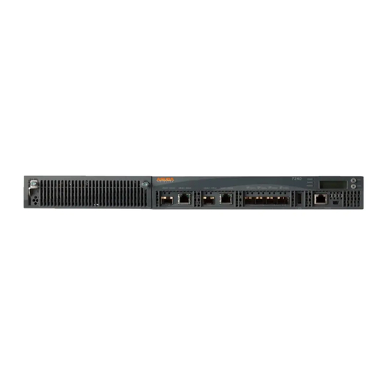
Table 5 Package Contents (Continued) Item Quantity End User License Agreement (Printed) Aruba Document Pointer (Printed) Optional accessories are available for use with the Aruba 7200 Series and are sold separately. Contact your Aruba sales representative for details and assistance. Front Panel The front panel of the Aruba 7200 mobility controller contains the following components: Four 10GBase-X (SFP+) ports... -
Page 9: Base-T (Rj-45) Ports
priority over the 10/100/1000Base-T copper connection. If a link is detected on the 1000Base-X interface, the 10/100/1000Base-T connection will be disabled. Aruba tests and supports Aruba optics within their controller systems. Third party optics are not tested or supported; therefore, Aruba does not guarantee proper functionality of third party optics when used in an Aruba system. -
Page 10: Gbase-X (Sfp+) Ports
Table 6 10/100/1000Base-T Port LEDs Function LCD Mode Indicator Status Status Port status Administrative Green (Solid) Port Enabled Port Administratively Disabled Duplex Green (Solid) Full-duplex Half-duplex Speed Green (Solid) 1000 Mbps 10/100 Mbps Table 7 1000Base-X Port LEDs Function LCD Mode Indicator Status LINK/ACT... -
Page 11: Management/Status Led Indicators
LINK/ACT: on the left side of the port, displays the link status of the port. Status: on the right side of the port, displays the status of the port. The information displayed by this LED changes based on LCD’s mode. The LED behavior for each mode is describe in Table Table 8 10GBase-X Port LEDs Function... - Page 12 displays two lines of text with a maximum of 16 characters on each line. When using the LCD panel, the active line is indicated by an arrow next to the first letter. Figure 3 LCD Panel M E N U E N T E P O W S T A T...
- Page 13 The LED mode menu allows you to choose what information is communicated by the LEDs on each port. Refer to Table 8 on page 11 for descriptions of the LED behavior of each mode. Table 12 LCD Panel Mode: LED Mode Function/Menu Options Displays Administrative LED MODE: ADM - displays whether the port is administratively enabled or disabled.
-
Page 14: Disabling The Lcd Screen
Table 14 LCD Panel Mode: Maintenance Function/Menu Options Displays System Halt Allows you to halt the controller. Halt [no | yes] Exit Maintenance Menu EXIT MAINTENANCE Disabling the LCD Screen By default, the LCD screen is enabled. However, if your 7200 is deployed in a location without physical security, the LCD screen can be disabled through the CLI. -
Page 15: Console Port
Console Port A serial console port is provided for connection to a terminal, allowing for direct local management. The port’s RJ-45 female connector accepts an RS-232 serial cable with a male connector. Figure 4 Serial Console Port Pin-Out Serial RJ-45 Female Console Port Pin-Out Direction... -
Page 16: Rear Panel
Rear Panel The rear panel of the Aruba 7200 controller consists of the following components: Two power supply slots One fan tray slot Grounding point Figure 6 Rear Panel Fan Tray The 7200 is equipped with a field-replaceable, hot-swappable fan tray. Each fan tray features four individual fans that pull air through the chassis from the front through to the rear. -
Page 17: Power Supply
Table 16 Fan Tray Components Callout Component Description Left Latch Used to secure the left side of the fan tray to the chassis. Right Latch Used to secure the right side of the fan tray to the chassis. Handle Used to insert and remove the fan tray from the chassis. Figure 8 shows the airflow pattern for the 7200. -
Page 18: Redundancy
Redundancy With power redundancy, the 7200 can continue normal operation even when a power supply fails or is turned off. When multiple power supplies are installed, if one becomes unavailable (fails, or is turned off or removed) the remaining power supplies will attempt to provide full power for the device. If the device’s total power load does not exceed the combined rated output of the remaining, operational power supplies, the controller will continue to operate. -
Page 19: Leds
Table 17 Power Supply Components Callout Component Description Handle Used to insert and remove the power supply from the chassis. Power Supply Blanking Plate Covers the extra power supply slot. Do not operate your 7200 without this blanking plate or a power supply in either slot. LEDs Each power supply is equipped with three LEDs to help monitor the power supply module’s status. - Page 20 | 7200 Controller Aruba 7200 Series Controller | Installation Guide...
-
Page 21: Installation
Chapter 2 Installation Installation of the device should be performed by a trained installation professional. This chapter describes how to install an Aruba 7200 controller using the many mounting options available. The 7200 ships with an accessory kit that includes the equipment needed to install the controller in standard, two-point 19-inch telco rack. -
Page 22: Selecting A Location
Selecting a Location The 7200, like other network and computing devices, requires an “electronics friendly” environment. Reliable power. Verify that your electrical outlet is compatible with the 7200 power supplies. Cool, non-condensing ventilation For proper operation, the 7200 requires an environment with an ambient air temperature between 0 and 40 ºC (32 to 104 ºF). - Page 23 Figure 10 Rack Mount Brackets 4. Mount the controller within your organization’s rack system using four (two per bracket) M6 x 15mm phillips flat head screws and suitable screwdriver (see Figure 11). Figure 11 Rack Mount Installation 5. Leave a minimum of four inches (10cm) of space on the left and right side of the unit for proper air flow and ventilation.
-
Page 24: Table Or Shelf Installation
Table or Shelf Installation Required Tools and Equipment Rubber Feet (included) Installation Steps 1. Attach the included rubber feet to the bottom of the controller. 2. Place your controller in the location you have chosen. 3. Connect the AC power cord to the rear of the unit. 4. - Page 25 4. Slide the fan tray module into the controller. 5. Lift both the hinged captive screws into the lock position then secure the fan tray module by tightening the captive screws. Figure 12 Installing a Fan Tray Aruba 7200 Series Controller | Installation Guide Installation |...
-
Page 26: Installing And Removing A Power Supply
Installing and Removing a Power Supply Never insert or remove a power supply while the power cord is connected. Verify that cord has been disconnected from the power supply before installation or removal. Use standard ESD precautions when installing or removing a power supply module. The power supply modules are hot-swappable. -
Page 27: Removing A Power Supply
Removing a Power Supply To remove a power supply from your 7200: 1. Lift the power cord retaining clip from the power cord. 2. Remove the power cable connected to the power supply module. 3. Using a Phillips head screwdriver, loosen the hinged captive screw on the front of the power supply module. - Page 28 2. Insert the fiber optic cable into the SFP module. Ensure that the latch on the cable faces the top of the SFP module. 3. Slide the cable into place until a connection is made and an audible click is heard. To disconnect an LC fiber optic cable from an SFP-SX or SFP-LX module: 1.
-
Page 29: Chapter 3 Specifications, Safety, And Compliance
Storage Humidity Range: 5% - 95% (RH), non-condensing Safety and Regulatory Compliance Aruba Networks provides a multi-language document that contains country-specific restrictions and additional safety and regulatory information for all Aruba products. This document can be viewed or downloaded from the following location: www.arubanetworks.com/safety_addendum... -
Page 30: Regulatory Models
Regulatory Models This document covers the following models: Table 19 Regulatory Model Numbers Part Number Regulatory Model Number 7210 7210-IL ARCN0100 7210-US 7220 7220-IL ARCN0101 7220-US 7240 7240-IL ARCN0102 7240-US This device complies with Part 15 of the FCC Rules. Operation is subject to the following two conditions: (1) this device may not cause harmful interference, and (2) this device must accept any interference received, including interference that may cause undesired operation.”... -
Page 31: Eu Regulatory Conformance
This product is CE marked according to the provisions of the EMC Directive (2004/108/EC) - CE. Aruba Networks Inc., hereby declares that 7210; 7220 & 7240 device models are in compliance with the essential requirements and other relevant provisions of Directive (2004/108/EC). CE The Declaration of Conformity made under Directive 1999/5/EC is available for viewing at the following location in the EU community. -
Page 32: China Rohs
restricted materials under the RoHS Directive are Lead (including Solder used in printed circuit assemblies), Cadmium, Mercury, Hexavalent Chromium, and Bromine. Some Aruba products are subject to the exemptions listed in RoHS Directive Annex 7 (Lead in solder used in printed circuit assemblies). Products and packaging will be marked with the “RoHS”...
Need help?
Do you have a question about the 7210 and is the answer not in the manual?
Questions and answers