Table of Contents
Advertisement
SCALANCE XR-500
SIMATIC NET
Industrial Ethernet switches
SCALANCE XR-500
Operating Instructions
05/2014
A5E03275845-05
___________________
Introduction
___________________
Safety notes
___________________
Description of the device
___________________
Assembling
___________________
Connecting
___________________
Uninstalling
___________________
Upkeep and maintenance
___________________
Technical data
___________________
Dimension drawings
___________________
Certification
1
2
3
4
5
6
7
8
9
10
Advertisement
Table of Contents

Related Manuals for Siemens SCALANCE XR524-8C


Summary of Contents for Siemens SCALANCE XR524-8C
- Page 1 ___________________ SCALANCE XR-500 Introduction ___________________ Safety notes ___________________ Description of the device SIMATIC NET ___________________ Assembling Industrial Ethernet switches ___________________ SCALANCE XR-500 Connecting ___________________ Uninstalling Operating Instructions ___________________ Upkeep and maintenance ___________________ Technical data ___________________ Dimension drawings ___________________ Certification 05/2014 A5E03275845-05...
-
Page 2: Legal Information
Note the following: WARNING Siemens products may only be used for the applications described in the catalog and in the relevant technical documentation. If products and components from other manufacturers are used, these must be recommended or approved by Siemens. Proper transport, storage, installation, assembly, commissioning, operation and maintenance are required to ensure that the products operate safely and without any problems. - Page 3 Mounting the PS598-1 power supply unit on the rear panel of modular device ......43 Connecting ..........................45 Commissioning........................45 24 VDC power supply ......................48 100 to 240 VAC power supply ....................50 5.3.1 Power supply for a SCALANCE XR524-8C ................50 SCALANCE XR-500 Operating Instructions, 05/2014, A5E03275845-05...
- Page 4 Downloading new firmware using TFTP without WBM and CLI ..........72 Restoring the factory settings ....................73 Technical data ..........................75 Technical specifications of the SCALANCE XR524-8C ............75 Technical specifications of the SCALANCE XR528-6M ............78 Technical specifications of the SCALANCE XR552-12M ............80 Switching properties ........................82...
-
Page 5: Introduction
The configuration and the integration of the device in a network are not described in these operating instructions. Validity of the Operating Instructions These operating instructions apply to the following devices: ● SCALANCE XR524-8C ● SCALANCE XR528-6M ● SCALANCE XR552-12M Designations used... - Page 6 ● On the data medium that ships with some products: – Product CD / product DVD – SIMATIC NET Manual Collection ● On the Internet pages of Siemens Industry Online Support under the following entry IDs: – 27069465 (http://support.automation.siemens.com/WW/view/en/27069465) Industrial Ethernet / PROFINET Industrial Ethernet System Manual –...
- Page 7 ● On the Internet under the following entry ID: 50305045 (http://support.automation.siemens.com/WW/view/en/50305045) Catalogs You will find the order numbers for the Siemens products of relevance here in the following catalogs: ● SIMATIC NET Industrial Communication / Industrial Identification, catalog IK PI ●...
- Page 8 Introduction Unpacking and checking WARNING Do not use any parts that show evidence of damage If you use damaged parts, there is no guarantee that the device will function according to the specification. If you use damaged parts, this can lead to the following problems: •...
-
Page 9: Safety Notes
The operating temperature of a device of the SCALANCE XR-500 product line depends on the ambient temperature. For SCALANCE XR524-8C, the ambient temperature must not exceed 70 °C. For SCALANCE XR528-6M and SCALANCE XR552-12M, the ambient temperature must not exceed 60 °C. - Page 10 Safety notes NOTICE Suitable fusing for the power supply cables The current on the terminal may not exceed 25 A. Use a fuse, that protects against currents > 25 A. The fuse must meet the following requirements: In areas according to NEC or CEC: •...
-
Page 11: Description Of The Device
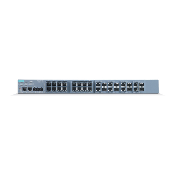
Description of the device Product overview The type designation of a SCALANCE XR-500 IE switch is made up of several parts that have the following meaning: Order numbers Device Order number Description XR524-8C 6GK5 524-8GS00-2AR2 1 height unit, 8 combo ports, 2 x 24 VDC, connector for the power supply on the front 6GK5 524-8GR00-2AR2 1 height unit, 8 combo ports, 2 x 24 VDC, connector for the power supply on... - Page 12 SFP+ XR524-8C XR528-6M XR552-12M Components of the product The following components ship with a SCALANCE XR-500: SCALANCE XR524-8C SCALANCE XR528-6M SCALANCE XR552-12M Device with exchangeable medium ● ● ● C-PLUG Product DVD with documentation and ●...
- Page 13 Restriction for pluggable transceivers for SCALANCE XR524-8C (2 x 24 VDC) If you use transceivers of the types LH, LH+, ELH or ELH200 with a SCALANCE XR524-8C (2 x 24 VDC), the maximum ambient temperature is reduced to 60 ℃.
- Page 14 Description of the device 3.1 Product overview Note No far-end fault detection for an SFP transceiver in the SFP+ slot If you use an SFP transceiver in an SFP+ slot, no far-end fault detection is possible for this interface. KEY-PLUG Type Order number KEY-PLUG XR-500...
- Page 15 Description of the device 3.1 Product overview Fan unit NOTICE Operation only with fan unit Use the devices SCALANCE XR528-6M and SCALANCE XR552-12M only with a correctly fitted fan unit. Operation without the fan is not possible and would damage the device. Type Order number FAN597-1 for SCALANCE XR552-12M...
-
Page 16: Select/Set Button
With a SCALANCE XR-500, the "SELECT/SET" button is on the front of the housing. The "SELECT/SET" button has several functions that are described below. Figure 3-1 SELECT/SET button on the SCALANCE XR524-8C Figure 3-2 SELECT/SET button on the SCALANCE XR552-12M SCALANCE XR528-6M is analogous. - Page 17 Description of the device 3.2 SELECT/SET button CAUTION Restart with the SELECT/SET button disabled for "Restore Factory Defaults" If you have disabled the SELECT/SET button for "Restore Factory Defaults" in the configuration, this does not apply during the startup phase. When you restart after cycling power, the configuration can nevertheless be deleted using this button.
-
Page 18: Led Display
Description of the device 3.3 LED display LED display 3.3.1 The "RM" LED for the "redundancy manager" function The "RM" LED indicates whether or not the device is a redundancy manager and whether or not the ring is operating free of error. LED color LED status Meaning... -
Page 19: The "F" Led For The Fault Status
Description of the device 3.3 LED display 3.3.3 The "F" LED for the fault status The "F" LED shows the fault/error status of the device. Meaning during device startup LED color LED status Meaning during device startup Device startup was completed successfully. Device startup is not yet completed or errors have occurred. -
Page 20: L1" And "L2" Leds For The Power Supply
Description of the device 3.3 LED display Setting the display mode To set the required display mode, press the "SELECT/SET" button. If you do not press the "SELECT/SET" button for longer than 1 minute, the device automatically changes to display mode A. Pressing SELECT/SET button LED status Display mode... - Page 21 Description of the device 3.3 LED display Meaning in display mode D In display mode D, the "L1" and "L2" LEDs indicate whether the power supply is monitored. Table 3- 3 Monitoring for devices with 24 VDC L1/L2 LED L1/L2 connector LED color LED status Power supply is not monitored.
-
Page 22: Port P1, P2, ... Leds For The Port Status
Description of the device 3.3 LED display 3.3.6 Port P1, P2, ... LEDs for the port status The port LEDs "P1", "P2" etc. show information about the corresponding ports. The meaning of the Port LEDs depends on the set display mode, see section ""DM1" and "DM2"... - Page 23 Description of the device 3.3 LED display Meaning in display mode C In display mode C, the port LEDs indicate the mode. LED color LED status Meaning Port operating in half duplex mode Green Port operating in full duplex mode Meaning in display mode D In display mode D, the port LEDs indicate whether the port is monitored.
-
Page 24: C-Plug / Key-Plug
Description of the device 3.4 C-PLUG / KEY-PLUG C-PLUG / KEY-PLUG 3.4.1 Function of the C-PLUG/KEY-PLUG NOTICE Do not remove or insert a C-PLUG/KEY-PLUG during operation A C-PLUG/KEY-PLUG may only be removed or inserted when the device is turned off. Saving configuration data and enabling layer 3 functionality A PLUG is an exchangeable storage medium for storing the configuration data of the device. -
Page 25: Removal And Insertion Of The C-Plug/Key-Plug
A C-PLUG/KEY-PLUG may only be removed or inserted when the device is turned off. Position of the C-PLUG/KEY-PLUG with rack devices On a SCALANCE XR524-8C, the slot is below a cover on the left-hand side of the housing. On a SCALANCE XR528-6M and SCALANCE XR552-12M, the slot is below a cover on the right-hand side of the housing. - Page 26 Description of the device 3.4 C-PLUG / KEY-PLUG Removing a C-PLUG/KEY-PLUG 1. Turn off the power to the device. 2. Remove the cover. 3. Insert a screwdriver between the front edge of the C- PLUG/KEY-PLUG (position A) and the slot and release the C-PLUG/KEY-PLUG.
-
Page 27: Combo Ports
Description of the device 3.5 Combo ports Combo ports The following devices have combo ports: ● SCALANCE XR524-8C Characteristics Combo port is the name for two communication ports. A combo port has the two following jacks: ● a fixed RJ-45 port ●... - Page 28 Description of the device 3.5 Combo ports SCALANCE XR-500 Operating Instructions, 05/2014, A5E03275845-05...
-
Page 29: Assembling
Assembling Safety notices for installation Safety notices When installing the device, keep to the safety notices listed below. CAUTION Use only approved components If you use components and accessories that are not approved for SIMATIC NET devices or their target systems, this may violate the requirements and regulations for safety and electromagnetic compatibility. - Page 30 Assembling 4.1 Safety notices for installation Note During installation and operation, keep to the installation guidelines and safety notices described in this document and in the system manuals "Industrial Ethernet / PROFINET Industrial Ethernet" and "Industrial Ethernet / PROFINET passive network components". You will find information on the system manuals in the section "Introduction (Page 5)", in "Further documentation".
-
Page 31: Types Of Installation
Assembling 4.2 Types of installation Types of installation Mounting the IE switches For the devices, you have the following options: ● 19" rack mounting ● Desktop operation with adhesive feet ● Secured at 4 points using special mounting brackets Mounting modular components For the modular components, you have the following options: ●... - Page 32 4.3 19" rack mounting Procedure Figure 4-1 19" rack mounting of the SCALANCE XR552-12M. SCALANCE XR524-8C/SCALANCE XR528-6M are mounted in the same way. To mount the device in a 19" rack, follow the steps below: 1. Secure the two mounting brackets with four screws each (M3 x 6 supplied with the ①...
-
Page 33: Desktop Operation With Adhesive Feet
Desktop operation of the SCALANCE XR528-6M and SCALANCE XR552-12M devices is permitted only when the power supply units are fitted to them. With SCALANCE XR524-8C, desktop operation is possible without restrictions. Note Strain relief for the cables A cable duct or cable tray must be present at a suitable distance from the device to provide strain relief. -
Page 34: Four-Point Mounting
For the SCALANCE XR524-8C, the mounting brackets for left and right are identical. For the SCALANCE XR524-8C, you can also use the mounting brackets intended for 19" rack mounting for the four-point mounting. Two suitable brackets ship with the device. Make the two missing mounting brackets according to the design drawings. - Page 35 Assembling 4.5 Four-point mounting Procedure Figure 4-2 Attaching the mounting bracket to a SCALANCE XR552-12M. SCALANCE XR524- 8C/SCALANCE XR528-6M are mounted in the same way. To install the device with a four-point mounting, follow the steps below: 1. Secure the four mounting brackets each with four countersunk screws (M3 x 6 supplied ①...
-
Page 36: Plugging And Pulling Mm900 Media Modules
Assembling 4.6 Plugging and pulling MM900 media modules Plugging and pulling MM900 media modules You can use media modules with the following devices: ● SCALANCE XR528-6M ● SCALANCE XR552-12M Notes on plugging/pulling media modules NOTICE Use only approved media modules In the module slots of the devices, use only approved media modules "MM900"... - Page 37 Assembling 4.6 Plugging and pulling MM900 media modules Identification of the media module slots and ports Below, you can see the arrangement of the slots and ports of a SCALANCE XR552-12M: Slot Port Slot Port Slot Port (SFP+) Slot Port Slot Port A SCALANCE XR528-6M has a total of six slots and four SFP+ ports.
- Page 38 Assembling 4.6 Plugging and pulling MM900 media modules Plugging in media module Figure 4-3 Plugging a media module into a SCALANCE XR552-12M. SCALANCE XR528-6M is used analogously. To use MM900 media modules in a modular SCALANCE XR-500, follow the steps below: 1.
- Page 39 Assembling 4.6 Plugging and pulling MM900 media modules Pulling a media module To pull a media module, follow the same steps as when plugging, but in the reverse order: 1. Pull out the handle of the media module. 2. Pull the media module out of the device slot. 3.
-
Page 40: Inserting And Removing Media Pluggable Transceivers
If you use SFP+ transceivers that are not approved for SIMATIC NET devices or their target systems, Siemens cannot accept any responsibility as to whether the Ethernet Switch system will function according to the specifications. Siemens can also not guarantee the compatibility and risk-free use of these components. -
Page 41: Inserting An Sfp / Sfp+ Transceiver
Assembling 4.7 Inserting and removing media pluggable transceivers 4.7.2 Inserting an SFP / SFP+ transceiver Follow the steps below to insert an SFP / SFP+ transceiver: 1. Remove the sealing plug of the SFP / SFP+ slot. 2. Close the clip of the SFP / SFP+ transceiver. 3. -
Page 42: Mounting Power Supply Units
Assembling 4.8 Mounting power supply units Mounting power supply units 4.8.1 19" rack mounting of the PS598-1 power supply unit Notes on 19" rack mounting of the PS598-1 power supply unit The PS598-1 was developed specifically for use with the SCALANCE XR528-6M and SCALANCE XR552-12M devices. -
Page 43: Mounting The Ps598-1 Power Supply Unit On The Rear Panel Of Modular Device
Assembling 4.8 Mounting power supply units 4.8.2 Mounting the PS598-1 power supply unit on the rear panel of modular device You can mount the PS598-1 power supply unit on the rear panel of the following devices: ● SCALANCE XR528-6M ● SCALANCE XR552-12M Procedure Figure 4-5 Rear panel mounting of the SCALANCE XR552-12M. - Page 44 Assembling 4.8 Mounting power supply units To mount the PS598-1 power supply unit on the rear panel of an IE switch, follow the steps below: ① 1. Fit the PS598-1 power supply unit and the IE switch together The two devices are equipped with positioning elements that must engage during installation and protect the plug from excessive bending strain.
-
Page 45: Connecting
Connecting Commissioning WARNING Commissioning devices and replacement devices If you use redundancy mechanisms (HRP/MRP ring redundancy and/or redundant coupling of rings with standby), open the redundant path before you insert a new or replacement device in an operational network. A bad configuration or attachment of the Ethernet cables to incorrectly configured ports causes overload in the network and a breakdown in communication. - Page 46 Connecting 5.1 Commissioning WARNING Operation only with safety extra-low voltage The device is designed for operation with a directly connectable safety extra-low voltage (SELV). (This does not apply to 100 to 240 V devices). This means that only safety extra-low voltages (SELV) complying with IEC 60950-1 / EN 60950-1 / VDE 0805-1 may be connected.
- Page 47 Connecting 5.1 Commissioning Safety notices on use in hazardous areas General safety notices relating to protection against explosion WARNING EXPLOSION HAZARD DO NOT CONNECT OR DISCONNECT EQUIPMENT WHEN A FLAMMABLE OR COMBUSTIBLE ATMOSPHERE IS PRESENT. Safety notices for use according to ATEX and IECEx If you use the device under ATEX or IECEx conditions you must also keep to the following safety notices in addition to the general safety notices for protection against explosion: WARNING...
-
Page 48: Vdc Power Supply
Connecting 5.2 24 VDC power supply 24 VDC power supply Notes on the power supply CAUTION Overvoltage protection for the power supply cables If SCALANCE XR-500s are supplied over long 24 V power supply lines or networks, measures are necessary to prevent interference by strong electromagnetic pulses on the supply lines. - Page 49 The SFP transceivers are supplied with suitable voltage via the SFP media module in a modular device. Position and assignment Figure 5-1 Position of the terminal block on a SCALANCE XR524-8C Figure 5-2 Position of the terminal block on a SCALANCE XR552-12M SCALANCE XR528-6M is analogous.
-
Page 50: To 240 Vac Power Supply
Information on the power supply The SCALANCE XR524-8C is available in the following versions for power supply with the 100 to 240 VAC power supply unit: ● With single power supply unit (1 x 100 to 240 VAC) ●... -
Page 51: Scalance Xr
The IEC plug S1 Power (position ) and the socket X1 (position ) for the input voltage are located on the rear of the SCALANCE XR524-8C. The second IEC plug for the redundant version is shown in gray in the figure. ①... -
Page 52: Power Supply Using The Ps598-1 Power Supply Unit
Connecting 5.3 100 to 240 VAC power supply 5.3.2 Power supply using the PS598-1 power supply unit 5.3.2.1 Connectors of the PS598-1 power supply unit Switches for the input voltage ① ③ The socket X1 (position ) and the switch S1 Power (position ) for the input voltage are located on the right-hand side of the front panel of the housing: ①... - Page 53 Connecting 5.3 100 to 240 VAC power supply NOTICE Reliable grounding Reliable grounding of the devices mounted in the rack must be guaranteed. This applies, in particular, to power supply cables that are not connected directly to the power supply circuit.
- Page 54 Connecting 5.3 100 to 240 VAC power supply Pin assignment of the X3 plug on the rear Connector X3 is located on the back of the PS598-1. Connector X3 is intended only to connect the PS598-1 directly to SCALANCE XR-528-6M and SCALANCE XR552-12M. Figure 5-6 Position of the plug X3 on the PS598-1 power supply unit Contact...
- Page 55 Connecting 5.3 100 to 240 VAC power supply Two PS598-1 per device, 1-out-of-2 redundancy Figure 5-8 Connecting two power supply units to a SCALANCE XR552-12M. SCALANCE XR528- 6M is used analogously. Connect the IE switch and the PS598-1 with one cable for 24 VDC and a cable for ground. As an alternative, you can also mount the two PS598-1 power supply units on the rear of the IE switch and secure them with screws.
-
Page 56: Led Display Of The Ps598-1 Power Supply Unit
Connecting 5.3 100 to 240 VAC power supply Connect each IE switch to its own PS598-1. In addition to this, connect both IE switches to the third PS598-1. Both IE switches devices can now continue to operate after the failure of one PS598-1. -
Page 57: Signaling Contact
(SELV)). Higher voltages or currents can damage the device! Position and assignment Figure 5-10 Position of the signaling contact on a SCALANCE XR524-8C Figure 5-11 Position of the signaling contact on a SCALANCE XR552-12M. SCALANCE XR528-6M is analogous. SCALANCE XR-500... - Page 58 Connecting 5.4 Signaling contact Signaling faults ● The signaling of errors/faults by the signaling contact is synchronized with the fault LED "F". All faults/errors indicated by the fault LED "F" (freely configurable) are also signaled by the signaling contact. ● If an internal fault occurs, the fault LED "F" lights up and the signaling contact opens. ●...
-
Page 59: Serial Interface
D-sub female connector. The connecting cable for the serial interface ships with the device. Position Figure 5-12 Position of the RJ-11 jack on a SCALANCE XR524-8C Figure 5-13 Position of the RJ-11 jack on a SCALANCE XR552-12M SCALANCE XR528-6M is analogous. - Page 60 Connecting 5.5 Serial interface Assignment of the terminal block The supplied connecting cable has the following assignment: Contact Pin assignment of the RJ-11 plug Pin assignment of the D-sub female connector TD (Transmit Data) TD (Transmit Data) RD (Receive Data) SG (Signal Ground) RD (Receive Data) SG (Signal Ground)
-
Page 61: Out-Of-Band Interface
● The out-of-band interface allows direct IP access to the WBM of the device. Position Figure 5-14 Position of the out-of-band interface on a SCALANCE XR524-8C Figure 5-15 Position of the out-of-band interface on a SCALANCE XR552-12M. SCALANCE XR528- 6M is analogous. -
Page 62: Block Architecture Of The Xr552-12M
Gbps. This bandwidth must be shared by all ports for inter-block data transfer. For this reason, ports between which a lot of data is transferred should ideally belong to the same switch block. Note that the SCALANCE XR524-8C and SCALANCE XR528-6M only have one switch block and do not require any block architecture. -
Page 63: Functional Ground
The connector for the grounding cable is in the center of the rear panel of the device. With a SCALANCE XR552-12M and SCALANCE XR528-6M, grounding is achieved with a screw-in bolt. The SCALANCE XR524-8C has a pressed-in grounding bolt. Fitting grounding bolts ①... - Page 64 Connecting 5.8 Functional ground Connecting up functional ground SCALANCE XR552-12M and SCALANCE XR528-6M SCALANCE XR524-8C ③ Grounding terminal with cable ④ Washer ⑤ Spring washer ⑥ Follow the steps below to connect the functional ground: ③ ④ ⑤ 1. Put the parts together on the grounding bolt as shown in the drawing.
-
Page 65: Uninstalling
Uninstalling Uninstalling the device 1. Remove all connectors. 2. Remove the power supply unit/units from the rear of the device. 3. When necessary release the locking mechanisms on the rack device (such as the handles on the media modules or the clip on the SFP/SFP+) to be able to remove the media modules (MM900) or the transceivers (SFP/SFP+). - Page 66 Uninstalling SCALANCE XR-500 Operating Instructions, 05/2014, A5E03275845-05...
-
Page 67: Upkeep And Maintenance
Upkeep and maintenance Changing the fan unit The following devices have a fan unit: ● SCALANCE XR528-6M ● SCALANCE XR552-12M NOTICE Operation of the SCALANCE XR-500 only with fan unit Use a SCALANCE X-500 only with a correctly fitted fan unit. Operating without the fan is not possible and would damage the device! You can, however, replace the fan unit during operation. - Page 68 Upkeep and maintenance 7.1 Changing the fan unit Procedure Follow the steps below to replace the fan unit: 1. Unlock the door in the housing by pushing the catch to the right with a slotted screwdriver ① Figure 7-1 Opening the housing of a SCALANCE XR552-12M. SCALANCE XR528-6M is used analogously.
- Page 69 Upkeep and maintenance 7.1 Changing the fan unit ④ 4. Disconnect the fan unit and the filter frame Figure 7-2 Changing the fan of a SCALANCE XR552-12M SCALANCE XR528-6M is used analogously. 5. Push the new fan unit into the slot along the guide rails. 6.
-
Page 70: Changing The Filter Pad
Upkeep and maintenance 7.2 Changing the filter pad Changing the filter pad The following devices have a filter pad: ● SCALANCE XR528-6M ● SCALANCE XR552-12M NOTICE Damage to the device due to inadequate ventilation A badly contaminated filter reduces air flow and can cause the device to be damaged. Check the degree of contamination of the filter regularly and clean or replace the filter mat as necessary. - Page 71 Upkeep and maintenance 7.2 Changing the filter pad ③ 3. Pull the filter frame out of the housing pulling on the strap of the filter frame Figure 7-4 Changing the filter pad of a SCALANCE XR552-12M SCALANCE XR528-6M is used analogously.
-
Page 72: Downloading New Firmware Using Tftp Without Wbm And Cli
7.3 Downloading new firmware using TFTP without WBM and CLI Downloading new firmware using TFTP without WBM and CLI Firmware The firmware is signed and encrypted. This ensures that only firmware created by Siemens can be downloaded to the device. Procedure with Microsoft Windows Using TFTP, you can supply a device with new firmware even when it cannot be reached using WBM or CLI. -
Page 73: Restoring The Factory Settings
Upkeep and maintenance 7.4 Restoring the factory settings Restoring the factory settings Procedure CAUTION Previous settings When you reset the device parameters, all previously changed settings are lost. CAUTION Reset despite disabled SELECT/SET button Using the SELECT/SET button, you can always reset the device parameters to the factory settings during the startup phase of the device. - Page 74 Upkeep and maintenance 7.4 Restoring the factory settings SCALANCE XR-500 Operating Instructions, 05/2014, A5E03275845-05...
-
Page 75: Technical Data
Technical data Technical specifications of the SCALANCE XR524-8C The following technical specifications apply to the SCALANCE XR524-8C. Technical specifications Attachment to Industrial Ethernet Electrical connectors * Quantity Connector RJ-45 jack Transmission speed 10 / 100/ 1000 Mbps Slots for pluggable transceivers... - Page 76 Technical data 8.1 Technical specifications of the SCALANCE XR524-8C Technical specifications 1 x 100 to 240 VAC Design IEC plug C14 with switch, 2-pin Rated voltage 100 / 240 VAC Voltage range 90 to 264 VAC Frequency 60 Hz / 50 Hz...
- Page 77 Technical data 8.1 Technical specifications of the SCALANCE XR524-8C Technical specifications Design, dimensions and weight Weight 2 x 24 VDC 3.8 kg 1 x 100 to 240 VAC 4.2 kg 2 x 100 to 240 VAC 4.5 kg Degree of protection...
-
Page 78: Technical Specifications Of The Scalance Xr528-6M
Technical data 8.2 Technical specifications of the SCALANCE XR528-6M Technical specifications of the SCALANCE XR528-6M The following technical specifications apply to the SCALANCE XR528-6M. Technical specifications Attachment to Industrial Ethernet Slots for media modules Quantity Slots for pluggable transceivers Quantity Connector SFP transceivers (LC port) Transmission speed... - Page 79 Technical data 8.2 Technical specifications of the SCALANCE XR528-6M Technical specifications Permitted ambient conditions Operating temperature Operation without filter pad and 0 to +60 °C without SFP+ LH transceiver Operation with filter pad and 0 to +55 °C without SFP+ LH transceiver Operation with filter pad and 0 to +50 °C with SFP+ LH transceiver...
-
Page 80: Technical Specifications Of The Scalance Xr552-12M
Technical data 8.3 Technical specifications of the SCALANCE XR552-12M Technical specifications of the SCALANCE XR552-12M The following technical specifications apply to the SCALANCE XR552-12M. Technical specifications Attachment to Industrial Ethernet Slots for media modules Quantity Slots for pluggable transceivers Quantity Connector SFP transceivers (LC port) Transmission speed... - Page 81 Technical data 8.3 Technical specifications of the SCALANCE XR552-12M Technical specifications Permitted ambient conditions Operating temperature Operation without filter pad and 0 to +60 ℃ without SFP+ LH transceiver Operation with filter pad and 0 to +55 ℃ without SFP+ LH transceiver Operation with filter pad and 0 to +50 ℃...
-
Page 82: Switching Properties
Technical data 8.4 Switching properties Switching properties The following technical specifications apply to the following device: ● SCALANCE XR524-8C ● SCALANCE XR528-6M ● SCALANCE XR552-12M Table 8- 1 Switching properties Max. number of learnable 16 000 addresses Aging time Can be configured (default value: 40 seconds) Switching technique Store&Forward... -
Page 83: Dimension Drawings
Dimension drawings SCALANCE XR524-8C View from front and above Dimensions are specified in mm. SCALANCE XR-500 Operating Instructions, 05/2014, A5E03275845-05... -
Page 84: Scalance Xr528-6M
Dimension drawings 9.2 SCALANCE XR528-6M SCALANCE XR528-6M View from front and above Dimensions are specified in mm. SCALANCE XR-500 Operating Instructions, 05/2014, A5E03275845-05... -
Page 85: Scalance Xr552-12M
Dimension drawings 9.3 SCALANCE XR552-12M SCALANCE XR552-12M View from front and above Dimensions are specified in mm. SCALANCE XR-500 Operating Instructions, 05/2014, A5E03275845-05... -
Page 86: Mounting Brackets For Use On Ships
Note Different mounting brackets For the SCALANCE XR524-8C, the mounting brackets for left and right are identical. For SCALANCE XR528-6M and SCALANCE XR552-12M, you require different mounting brackets. The mounting brackets on one side are identical but the mounting brackets for left and right are different. - Page 87 Dimension drawings 9.4 Mounting brackets for use on ships Mounting brackets for a SCALANCE XR524-8C View from the front, top, and side Dimensions are specified in mm. SCALANCE XR-500 Operating Instructions, 05/2014, A5E03275845-05...
- Page 88 Dimension drawings 9.4 Mounting brackets for use on ships Mounting bracket for a SCALANCE XR528-6M Mounting bracket left View from the front, top, and side (left) Dimensions are specified in mm. SCALANCE XR-500 Operating Instructions, 05/2014, A5E03275845-05...
- Page 89 Dimension drawings 9.4 Mounting brackets for use on ships Mounting bracket right View from the front, top, and side (right) Dimensions are specified in mm. SCALANCE XR-500 Operating Instructions, 05/2014, A5E03275845-05...
- Page 90 Dimension drawings 9.4 Mounting brackets for use on ships Mounting bracket for a SCALANCE XR552-12M Mounting bracket left View from the front, top, and side (left) Dimensions are specified in mm. SCALANCE XR-500 Operating Instructions, 05/2014, A5E03275845-05...
- Page 91 Dimension drawings 9.4 Mounting brackets for use on ships Mounting bracket right View from the front, top, and side (right) Dimensions are specified in mm. SCALANCE XR-500 Operating Instructions, 05/2014, A5E03275845-05...
- Page 92 Dimension drawings 9.4 Mounting brackets for use on ships SCALANCE XR-500 Operating Instructions, 05/2014, A5E03275845-05...
-
Page 93: Certification
Certification The SIMATIC NET products described in these Operating Instructions have the approvals listed below. Note Issued approvals on the type plate of the device The specified approvals apply only when the corresponding mark is printed on the product. You can check which of the following approvals have been granted for your product by the markings on the type plate. - Page 94 Safety of electrical equipment In the version put into circulation by Siemens AG, the SIMATIC NET products described in these Operating Instructions conform to the regulations of the following European directive: ●...
- Page 95 Area". You will find this document • on the data medium that ships with some devices. • on the Internet pages of Siemens Industry Online Support (http://support.automation.siemens.com/WW/view/en). Enter the document identification number C234 as the search term. SIMATIC NET products meet the requirements of the EC directive:94/9/EC "Equipment and Protective Devices for Use in Potentially Explosive Atmospheres".
- Page 96 Certification 9.4 Mounting brackets for use on ships IECEx The SIMATIC NET products meet the requirements of explosion protection according to IECEx. IECEx classification: Ex nA IIC T4 Gc DEK 14.0025X The products meet the requirements of the following standards: ●...
-
Page 97: Fda And Iec Marks
Only variants with 24 VDC power supply meet the requirements of this approval. EU declaration of conformity You will find EC declaration of conformity for these products on the Internet pages of Siemens Industry Online Support (http://support.automation.siemens.com/WW/view/en/33118389/134200). 10.1 FDA and IEC marks... -
Page 98: Mechanical Stability (In Operation)
10 - 58 Hz: 0.075 mm 15 g, 11 ms duration 9 - 150 Hz: 1 g 85 - 150 Hz: 1 g 6 shocks per axis 1 octave/min, 20 sweeps 1 octave/min, 20 sweeps SCALANCE XR524-8C ● ● ● SCALANCE XR528-6M ● ●... -
Page 99: Index
Index Firmware, 19, 72 Four-point mounting, 31, 34 Front terminal, 33 Functional ground, 63 19" rack mounting, 31 Glossary, 7 Accessories, 13 Grounding, 63 Adhesive foot, 12, 33 Grounding bolt, 63 Ambient temperature, 9 Handle, 38 Bolt, 63 Bracket, 12, 31, 34, 63, 86 IEC plug, 51 Installation location, 9 CLI, 5, 25, 59, 72... -
Page 100: Scalance Xr
Index Terminal block, 12, 48, 57 Transmission speed, 22 PLUG, 24 Type designation, 11 Pluggable transceiver, 12 Type of installation, 31 Pluggable transceiver slot, 12 Port status, 22 Power cable, 13 Power supply, 20, 48, 50, 52 Power supply unit, 15, 31, 33, 42, 52 Ventilation slit, 29, 42 Voltage limit, 20 Redundancy manager, 17...