Table of Contents
Advertisement
Quick Links
Advertisement
Table of Contents

Subscribe to Our Youtube Channel
Related Manuals for Intelligent Home DT591


Summary of Contents for Intelligent Home DT591
- Page 1 Door Station DT591/592 2-wire series DT591 DT592 www.intelligenthomeonline.com...
- Page 2 CONTENTS...
-
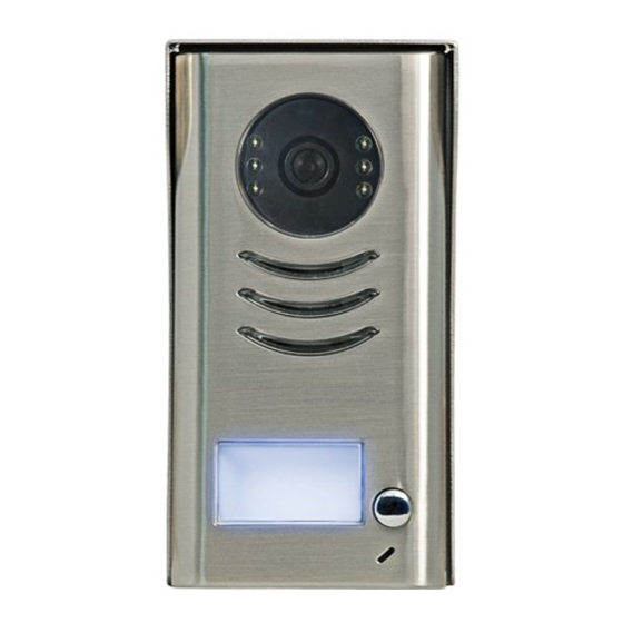
Page 3: Parts And Functions
1.Parts and Functions Camera Lens Night Viision LED Speaker Nameplate Call Button Microphone Rain Cover 90 mm 23 mm DT592 with 2-call buttons shown 2.Terminal Descriptions 1 2 3 Lock Control Jumper Doorstation Code DIP MIC adjustment SPK adjustment Main Connect Port - 1-... - Page 4 • Keep or remove the Jumper for different types of electric locks- see 5.2.1 , 5.2.2 Lock Control Jumper: • To set the address for multiple door stations -see 6.1 Doorstation Code DIP switches: • To connect the bus line and the electric locks Main Connect Port: •...
-
Page 5: Placing Name Label
4.2 Mounting With Rain Cover 160-165cm 4.3 Placing Name Label Move the plastic cover away to open the transparent name label cover, insert a paper, then put the plastic cover back name label - 3-... -
Page 6: Adjusting Camera Angle
4.4 Adjusting Camera Angle use a screwdriver to loosen the screw and then adjust the angle 5.System Wiring and Connections 5.1 Basic Connection monitor monitor BUS(IM) BUS(DS) L1 L2 PL S1+ S2+ S- L1 L2 PL S1+ S2+ S- - 4-... -
Page 7: Electric Lock Connection
5.2 Electric Lock Connection 5.2.1 Electric Power-on-to-open lock powered by the system 1. Only Power-on-to-open electric locks can be connected 2. The lock is limited to 12V, and holding current must be not more than 250mA 3. The door lock control is not timed when Exit Button used 4. - Page 8 Mode 1 for Power-off-to open electric, and all magnetic locks Connect the whole system including the lock, and power it up. On any of video monitor touch “About” or “Intelligent Home” icon. Page with software info will open Touch and hold screen and then go to “Installer Setup”...
-
Page 9: Multi Doorstations Connection
5.3 Multi Doorstations Connection 4# Camera 3# Camera 2# Camera 1# Camera ID=11 ID=01 ID=10 ID=00 L1 L2 PL S1+ S2+ S- L1 L2 PL S1+ S2+ S- L1 L2 PL S1+ S2+ S- L1 L2 PL S1+ S2+ S- DIP=on,off,off A B C D DBC-4S... -
Page 10: Multi Monitors Connection
5.4 Multi Monitors Connection 5.4.1 Basic Daisy Chain Connection monitor 3 4 5 6 Code=15, DIP-6=on monitor 3 4 5 6 Code=14, DIP-6=off monitor 3 4 5 6 Code=0, DIP-6=off 85~260AC ID=00 - 8 -... - Page 11 5.4.2 Star Connection with DBC-4S distributors monitor monitor 3 4 5 6 3 4 5 6 Impedance OFF ON switch Code=14, DIP-6=on Code=15, DIP-6=on DIP=on,off,off monitor monitor 3 4 5 6 3 4 5 6 Code=12, DIP-6=on Code=13, DIP-6=on monitor monitor 3 4 5 6 3 4 5 6...
- Page 12 6. Setup via DIP switches ON(1) OFF(0) 6.1 DIP Switches Settings of Single and Multiple Doorstations Dip state Door Station ID ID = 1(10) for the second Door Station ID = 2(01) for the third Door Station ID = 3(11) for the fourth Door Station 6.2 DIP Switches Settings of Video Monitors Use Tables on page 11 for programming monitor User Codes DIP switch 6 is END of LINE switch, which have to be set ON if the Monitor is in the end of the line (bus), otherwise set OFF...
- Page 13 USER CODE TABLE DIP switches 1-5 are used to give unique address - USER CODE to each video monitor in the system. Bit state User Code Bit state User Code Bit state User Code Code=0 Code=11 Code=22 3 4 5 3 4 5 3 4 5 Code=1...
-
Page 14: Cable Requirements
7.Cable Requirements This system transmits video and audio through the power cable. No Polarity connection • Recommended cables: twisted pair, power flex multi-cores, speaker cable, CAT5/CAT6 • Minimum requirements 0.5mm cable up to 2mm (depends on distance) The furthest monitor monitor two or four monitors monitor... -
Page 15: Warranty Card
4. Attempting to force the device to perform functions for which it is not intended 5. Attaching the device to power supplies other than thoserecommended by the manufacturer Distributor for Warranty purposes: Intelligent Home Online Ltd 62 Hartley Old Road Purley Surrey... - Page 16 The design and specifications can be changed without notice to the user. Right to interpret and copyright of this manual are preserved. www.intelligenthomeonline.com...
Need help?
Do you have a question about the DT591 and is the answer not in the manual?
Questions and answers