Table of Contents
Advertisement
Quick Links
Advertisement
Table of Contents

Subscribe to Our Youtube Channel
Related Manuals for Spirit XR895


Summary of Contents for Spirit XR895
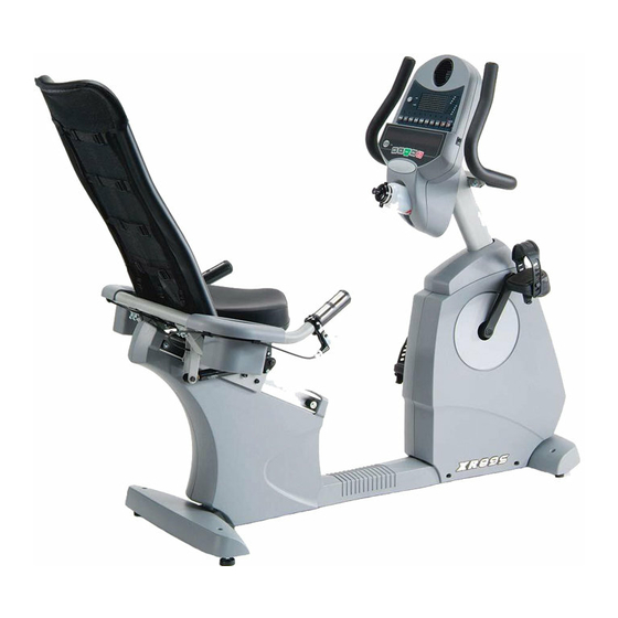
- Page 1 XR895 Service Manual Release Lever console Front Stabilizer Cover Round Disk Cover Rear Stabilizer Cover Bottom Cover Console Mast Cover Rear Chain Cover (L) Cup Holder (R) Front Chain Cover (R) Cup Holder (L) Rear Chain Cover (R) Front Chain Cover (L)
- Page 2 Structure Seat Back Frame Seat Carriage Handle Console Mast Seat Handle Bar Rear Stabilizer Controller Mainframe Flywheel Drive Pulley Cylinder Aluminum Rail Crank Idle Arm...
-
Page 3: Table Of Contents
Content 1. Dismantle and Replacement 1. Console 2. Handle and Console Mast 3. Cranks and Pedals 4. Front Chain Cover 5. Belt and Idle Arm 6. Drive Pulley Axle and Drive Pulley 7. Generator Flywheel 8. Cylinder 9. Seat Back 10. -
Page 4: Dismantle And Replacement
1. Dismantle and Replacement 1. Console (19) dismantle and assembling Unscrew 4pcs of M5x12m/m Phillips Head Screws (99) with Phillips Head Screw Drier (114) and the Console can be released. 2 Handle (3) and Console Mast 1. Take off the Handle Bar Cover (141) then use 12/14 m/m wrench (112) to release 2pcs of 5/16”x15 Hex Head Screws (68), 2pcs of ψ8x1.5T Split Washers and 2pcs of 5/16”x19x1.5T Flat Washers (76) and the Handlebar Assembly (3) can be released. - Page 5 4. To resume the Console Mast (2), guide the computer cable through the Console Mast (2) and out of the console plate first and the use 12 m/m wrench to tighten 6pcs of 5/16”x15 Hex Head Screws (68) together with 4pcs of 5/16" x 19 x 1.5T Flat Washers (76) and 2pcs of 5/16" x20x 1.5Tcurved Washers (83).
- Page 6 4. Use the plug matching with the Cranks (51L, 51R) and turn with hex wrench to release the Cranks (51L, 51R). 5.To resume the Cranks (51L, 51R), use the hammer to hit the Cranks tightly match with the Drive Pulley Axle (8) and turn the nut tightly onto the Axle. Plug in the Crank Arm End Cap. 4.
- Page 7 3. To resume the Right Front Chain Cover, put it on the mainframe and plug in the electric wires back to the AC power switch. Locate 2pcs ofψ3.5x20 Self Tapping Screws (107) with 2pcs ofψ5 x16x1.5T Flat Washers (78) on the mainframe loosely then tighten 2pcs of 5x16 Tapping Screws (102) on the mainframe and tighten up all loose screws.
-
Page 8: Generator Flywheel
4. To resume the Belt (54) and Idle Arm (10), use Phillips Head Screw Driver to secure the Generator Flywheel (55) with 3pcs of M6x15 Phillips Head Screws together with 3pcs ofψ1/4" Split Washers (80) and 3pcs of 1/4”x13x1T Flat Washers (72). Turn the Drive Pulley (20) to let the Belt on the Pulley, hook the J-Bolt on the mainframe and use 13 m/m wrench to tighten M8x7T Nut (88) on the J-Bolt until the Belt (54) is with acceptable tension. - Page 9 4pcs ofψ1/4"Split Washers (80) and you can release Generator Flywheel (55). 2. Reverse the above step to resume the Generator Flywheel (55). 8. Disassembling/Assembling Cylinder (57) 1. On Left and Right Cup Holder (38, 39) use Phillips Head Screw Driver to unscrew 4pcs ofψ4x16 Self Tapping Screws (105) to take off Cup Holders (38,39) 2.
- Page 10 unscrew 5/16" x2- 1/2"(Grade 8) Hex Head Screw (69) with 5/16"x19 x 1.5T Flat Washer (76) and 5/16"x 6T Nut (91) on the Seat Carriage (4) and you can release the Cylinder (57). 6. Use 5/16" x2- 1/2"(Grade 8) Hex Head Screw (69) with 5/16"x19 x 1.5T Flat Washer (76) and 5/16"x 6T Nut (91) to secure the Cylinder (57) on the Seat Carriage (4) and connect the Seat Recline Release Cable (58) to the Cylinder (57).
- Page 11 3/8”x4”Hex Head Screws (67) with 2pcs of 3/8"x7T Nut (89) by using 2pcs of 14 m/m wrench. 10. Disassembling/Assembling Rear Chain Covers (L) and (R) (35, 36) 1. Use Phillips Head Screw Driver to unscrew 7pcs ofψ3.5x12 Self Tapping Screws (103) and 2pcs of 5x16 Tapping Screws (102), which are on Left Rear Chain Cover (35).
- Page 12 Lever (40) and slide out the Seat Carriage. 3. Use Phillips Head Screw Driver to unscrew 4pcs of M6x15 Phillips Head Screws (98) on the Seat Carriage (4) and the Seat Bottom Cushion can be released. 4. Use M5 Allen Wrench/Phillips Head Screw Driver Combination (115) to release Left Release Lever (40).
-
Page 13: Problem Solving
7. Use 13 m/m wrench to release M8 x 7T Black Nyloc But (88) andψ8x18x3T Lock Washer (79), which are on the Seat Carriage, and the Seat Wheel Adjustment Plate (9) can be removed. 8. To resume Seat Carriage (4), locate the Seat Wheel Adjustment Plate (9) with screws loosely and secure the Seat Positioning Latch (12), Seat Recline Release Cable (59) and Seat Release Spring (104) with M6 x40mm Socket Head Cap Screw (93) and M6 Nut (129). -
Page 14: Belt And Idle Arm
3 .Belt and Idle Arm 1.When the Belt (54) falls off, refer to step 4 in item 1 to disassemble Chain Covers and Idle Arm (10), referring to step 5 in item 1. Then refer to steps in item 1 to resume the Belt and check the running of the belt at low speed to investigate the swing of the Drive Pulley (20) and the Belt (54) and the alignment of the Belt (54), Drive Pulley (20) and Generator Flywheel.
Need help?
Do you have a question about the XR895 and is the answer not in the manual?
Questions and answers