Table of Contents
Advertisement
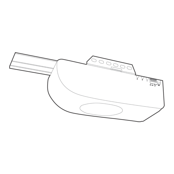
model no. 046-0266-0
IMPORTANT:
• Please read this manual and enclosed safety materials carefully.
• Safety infrared sensor MUST BE INSTALLED and aligned properly.
• Periodic checks of the opener are required to ensure safe
operation.
• Save this manual for future reference.
• This equipment meets or exceeds all federal, provincial and
UL325 safety requirements.
DO NOT RETURN THIS TO THE STORE
Please call: 1-800-689-9928.
GARAGE DOOR OPENER
BELT DRIVE
INSTRUCTION
MANUAL
Advertisement
Table of Contents

Subscribe to Our Youtube Channel
Related Manuals for MasterCraft 046-0266-0

Summary of Contents for MasterCraft 046-0266-0
- Page 1 046-0266-0 BELT DRIVE GARAGE DOOR OPENER IMPORTANT: • Please read this manual and enclosed safety materials carefully. • Safety infrared sensor MUST BE INSTALLED and aligned properly. INSTRUCTION • Periodic checks of the opener are required to ensure safe MANUAL operation.
- Page 2 headline bars continuation tabs notes warnings...
-
Page 3: Table Of Contents
TABLE OF CONTENTS Introduction Pre-Installation Checklist What is Included Important Instructions 10-11 Assemble The T-Rail 12-16 Install The Header Bracket 17-20 Hang The Opener 21-22 Install The Door Bracket 23-24 Install The Door Arms 25-27 Install The Wall Console 28-29 Connect The Opener To Power 30-31 Install Safety Beam Sensor... - Page 4 046-0266-0 | contact us 1-800-689-9928 continuation tabs continuation tabs notes notes BLANK PAGE (ON PURPOSE) warnings warnings...
-
Page 5: Introduction
INTRODUCTION Congratulations on purchasing the Mastercraft® Belt Drive Garage Door Opener — a garage door opener with many innovative features. Features include: extremely quiet operation with DC motor; automatic force adjustment so the door can be closed with just the right amount of force, not overpowered;... -
Page 6: Pre-Installation Checklist
046-0266-0 | contact us 1-800-689-9928 PRE-INSTALLATION CHECKLIST Check the following items before assembling the opener: • Identify the door type: sectional door or one-piece jamb door. • Ensure your garage door is balanced and is not sticking or binding. -
Page 7: What Is Included
WHAT IS INCLUDED The garage door opener and all accessories are packaged in one carton. Note that accessories will depend on the model you purchased. If anything is missing, carefully check the packing material. Wall Console Keychain Remote Keyless Entry Safety Beam Unit Trolley Pulley Assembly... - Page 8 046-0266-0 | contact us 1-800-689-9928 Emergency Release Rope continuation tabs notes Chain and Cable Hanging Assembly Bracket warnings Straight Arm Rail Sections...
- Page 9 BAG A A1 x 12 A2 x 12 A3 x 2 A4 x 3 A5 x 3 Carriage Bolt Locknut Bolt Locknut Flange Bolt BAG B B1 x 4 B2 x 4 B3 x 2 Lag Screw Bolt Self-tapping Screw B4 x 1 B5 x 1 Clevis Pin...
-
Page 10: Important Instructions
046-0266-0 | contact us 1-800-689-9928 IMPORTANT INSTRUCTIONS WARNING To reduce the risk of severe injury or death: 1. READ AND FOLLOW ALL INSTALLATION INSTRUCTIONS. 2. Check with the door manufacturer to determine if additional reinforcement is required to support the door prior to installation of the garage door opener. - Page 11 An overall view of a completed garage door opener system installed on a sectional door. The arrangement is similar for a one-piece jamb door (except for differences described later in this manual).
-
Page 12: Assemble The T-Rail
046-0266-0 | contact us 1-800-689-9928 ASSEMBLE THE T-RAIL ΠConnect the T-Rail Sections Align the 4 T-Rail sections on the floor. Connect these rails together with the rail couplers as shown. All rail pieces must be aligned properly. -
Page 13: Install The Trolley
Please note the arrow and “M” marking which indicates this side to the motor unit. Attach the Tensioner Pulley Assembly Attach the tensioner pulley assembly to the end of the front rail with 2 nuts and bolts. Align the tensioner pulley assembly and rail. - Page 14 046-0266-0 | contact us 1-800-689-9928 Attach the T-Rail to the Opener Raise the pulley end of the rail so the rail can sit on the motor unit properly. Attach the rail to the motor unit by tightening 2 screws. Insert a bolt to the stop bolt hole and secure it with nut.
- Page 15 ’ Align the Belt on the Sprocket Start aligning the belt by placing the turnbuckle 10” (25 cm) from the sprocket. Wrap the belt around the sprocket. The sprocket must engage the belt as shown. “ Place the Belt on the Pulley Place the belt around the pulley at the end of the rail.
-
Page 16: Attaching The Sprocket Cover
046-0266-0 | contact us 1-800-689-9928 ” Attaching the Sprocket Cover Squeeze the cover slightly and insert the 2 tabs on the cover in the slots on the motor unit. continuation tabs continuation tabs notes... -
Page 17: Install The Header Bracket
INSTALL THE HEADER BRACKET Œ Mark the Door Centreline Close the door from inside the garage and mark the vertical centreline of the door on the wall and the top door panel. Sectional Door One-piece Jamb Door WARNING • Header bracket must be secured to structural supports. If appropriate support does not exist, install a new support using 2x4 board on drywall or between 2 studs with lag screws (not included). -
Page 18: Install The Header Bracket
046-0266-0 | contact us 1-800-689-9928 Mark Above the Highest Point of Travel 1 1/4” (3 cm) above highest point of travel 1 1/4” ( 3 cm) 7” (18 cm) Highest point of travel continuation tabs... -
Page 19: Attach The Header Bracket
Attach the Header Bracket Place the bottom edge of the bracket on the line marked above the highest point of travel. Mark the 2 holes with a pencil. 1 1/4" (3 cm) Above Sectional Door/ 7" (18 cm) Above One-piece Jamb Door Highest Point of Travel Drill two 3/16"... - Page 20 046-0266-0 | contact us 1-800-689-9928 Position The Opener Position the pulley bracket against the header bracket. continuation tabs continuation tabs notes notes Position the opener on the floor with packaging material as protective base.
-
Page 21: Hang The Opener
HANG THE OPENER ΠRaise the Opener Raise the opener onto a stepladder. Use extra spacers on top of the ladder if the ladder is not tall enough. Carefully raise the door to the fully open position. Be sure the door is clear from the rail or any other part of the opener. -
Page 22: Attach The Hanging Brackets
046-0266-0 | contact us 1-800-689-9928 Attach the Hanging Brackets Hanging brackets should be angled to provide rigid support. Measure the distance from the motor unit to the structural support. Cut and bend the hanging brackets as required. -
Page 23: Install The Door Bracket
INSTALL THE DOOR BRACKET Top of Door Door Bracket Location Hardware Door arm connects directly (not included) to vertical reinforcement Bolt 5/16 x 2" (8 x 50 mm) Sectional Wood Doors (not included) For wood doors, drill 5/16" (8 mm) holes through the door and secure bracket with 5/16 x 2"... - Page 24 046-0266-0 | contact us 1-800-689-9928 One-Piece Wood Doors Bolt 5/16 x 2" (8 x 50 mm) (not included) For wood doors, drill 5/16" (8 mm) holes through the door and secure bracket with 5/16 x 2" (8 x 50 mm) carriage bolts, lock washers and nuts (not included).
-
Page 25: Install The Door Arms
INSTALL THE DOOR ARMS ΠAttach Emergency Release Rope Engaged Released Thread the red rope through the hole in the trolley release handle and tie an over-hand knot. Leave the trolley release lever in the released position until further testing is completed. ... -
Page 26: Connect The Door Arm To The Trolley
046-0266-0 | contact us 1-800-689-9928 Ž Connect the Door Arm to the Trolley Sectional Door Connect the straight door arm to the trolley with clevis pin and hitch pin. continuation tabs notes One-piece Jamb Door Connect the curved door arm to the trolley with clevis pin and hitch pin. - Page 27 Connect the Door Arms Together Bring two arms together. Find two pairs of holes that line up and join 2 arms with bolts and nuts. Select holes as far apart as possible to increase door arm rigidity. Sectional Door One-piece Jamb Door...
-
Page 28: Install The Wall Console
046-0266-0 | contact us 1-800-689-9928 INSTALL THE WALL CONSOLE continuation tabs continuation tabs Œ 5' (1.5 m) notes notes Place the wall button or wall console at least 5’ (1.5 m) above the finished floor or the topmost step. - Page 29 Mount the user safety instruction label next to the wall console. Route the wire up the wall and across the ceiling to the opener with wire holders. ‘ Connect the wires to the terminals . Wires are not polarity sensitivity (either wire to either terminal). White Black...
-
Page 30: Connect The Opener To Power
046-0266-0 | contact us 1-800-689-9928 CONNECT THE OPENER TO POWER ΠConnect AC Power Plug motor unit into grounded outlet. If a grounded outlet is not available, contact a qualified electrician to install a proper outlet. - Page 31 Permanent Wiring/Remove the Bushing Be sure the power cord is unplugged. Cut the cord about 6" (15 cm) above the bushing. Remove the bushing with pliers. Permanent Wiring/Hardwire the Opener Green РGround White РNeutral Black РHot Connect conduit wiring to opener wiring with wire nuts (not included).
-
Page 32: Install Safety Beam Sensor
046-0266-0 | contact us 1-800-689-9928 INSTALL SAFETY BEAM SENSOR continuation tabs continuation tabs Important Information: The safety beam sensor can detect obstacles in the path of its invisible beam. When the beam is obstructed while the door is closing, the door will stop immediately, reverse to the fully open position and the opener lights will flash. -
Page 33: Mounting The Sensor On The Door Track
Mounting the Sensor on the Door Track Clip the mounting bracket onto the garage door track. Ensure the sensor is mounted between 4" (10 cm) and 6" (15 cm) above the ground. Follow the same procedure to install the sensor on the other track ensuring the sensors are facing each other. - Page 34 046-0266-0 | contact us 1-800-689-9928 NOTE: Remove the spring bracket from the mounting bracket if installing to the wall or floor. 1. Slide the sensor from the mounting bracket. 2. Slide the spring bracket from the mounting bracket.
-
Page 35: Align The Safety Beam Sensor
’ Check the Safety Beam Sensor LED Plug in the opener. The receiving sensor indicator's blue LED should glow steadily if the wiring and alignment are correct. The transmitting sensor indicator's red LED will glow steadily regardless of alignment or obstruction. Align the sensors “... - Page 36 046-0266-0 | contact us 1-800-689-9928 ” Testing with Obstruction With the sensors properly aligned, place an obstacle in the path of the beam. The transmitting sensor's red LED should be on, the receiving sensor's blue LED should be off.
-
Page 37: Programming Guide - Wall Console
PROGRAMMING GUIDE – WALL CONSOLE While programming, the UP and DOWN buttons can be used to move the door as needed. 1. Connect the opener to an approved power source. The dot in the LED display stays on. 2. Press and hold button on the wall console for 5 seconds until the LCD display shows the number “1”... - Page 38 046-0266-0 | contact us 1-800-689-9928 14. The garage door opener will beep once when door is fully closed and the display will show “F”. 15. Press the Ç or È button to set the force 0, 1, 2, or 3.
- Page 39 22. The LCD display will show the tim. setting. 23. Press the Ç/È buttons to set the hour to the current time; then, press confirm. 24. Press the Ç/È buttons to set the minute to the current time; then, press confirm.
-
Page 40: Programming Guide - Garage Door Opener
046-0266-0 | contact us 1-800-689-9928 PROGRAMMING GUIDE – GARAGE DOOR OPENER While programming, the p and q buttons can be used to move the door as needed. A. Set Up Travel Limit and Open/Close Force 1. - Page 41 B. Changing Force 1. Press and hold the [SET] button for 10 seconds. When the LED display shows “F”, SET FORCE LEVEL release the [SET]button. 2. The LED display will show “0”. 3. Press the p or q button to set the force 0, 1, 2 or 3.
- Page 42 046-0266-0 | contact us 1-800-689-9928 D. Erasing all the Remote Controls from Opener Note: To erase any unwanted remote controls, first erase all remotes. 1. Press the [SET] button for 15 seconds. When the LED display flashes “E”, release the [SET]button.
-
Page 43: Safety Tests
SAFETY TESTS Test Safety Reversal System With the door fully open, place a 1 1/2" (3.8 cm) board (or 2x4 laid flat) on the floor, centred under the garage door. Close the door by pressing the button on the wall console. After making contact with the board, the door should stop then reverse to a fully open position. -
Page 44: Operation
046-0266-0 | contact us 1-800-689-9928 OPERATION Important Safety Instructions WARNING To reduce the risk of severe injury or death: continuation tabs continuation tabs 1. READ AND FOLLOW ALL INSTRUCTIONS CAREFULLY. 2. NEVER let children operate or play with any garage door controls or remote controls. Always keep these controls away from children. -
Page 45: Operation
Operating the Door Activate your opener by: • Pressing the wall console. • Pressing the assigned button on the remote control. Depending on the status of the garage door opener and the position of the garage door, the garage door opener behaves in different ways: •... - Page 46 046-0266-0 | contact us 1-800-689-9928 Set Up Auto Closer The opener has the option to program how long until the door closes automatically after it has been opened. 1. Press and hold button for 5 seconds.
-
Page 47: Maintenance
MAINTENANCE Once a Month • Test the door balance. Manually operate door. If it is unbalanced or binding, call a trained door systems technician. • Check to be sure door opens and closes fully. Adjust limits and/or force if necessary. •... -
Page 48: Battery Replacement
046-0266-0 | contact us 1-800-689-9928 Battery Replacement All remotes come with battery installed. To replace the battery, follow the instructions below. It is time to change the battery when the red LED light on the remote does not turn on when either button is pressed. -
Page 49: Backup Battery
BACKUP BATTERY Œ Press the latch inwards to release the cover. Remove the cover. Ž Take out the battery and connect the wires to the battery terminal tabs, being careful to match the polarity. Red wire connects to red terminal tab (+). ... - Page 50 046-0266-0 | contact us 1-800-689-9928 NOTE: • These steps must be performed in this exact order very carefully to prevent a short in the battery by accident. Connecting the battery backup unit to the garage door opener unit Œ...
-
Page 51: Backup Battery
Battery Status LIGHT STATUS STATUS ACTION Red LED flashing slowly. Fully charged (AC adaptor is Ready to provide power to unplugged). garage door opener. Red LED staying on. Backup battery is weak (AC adaptor is Needs to re-charge. unplugged). Blue LED flashing slowly. Backup battery is being charged (AC Charging. -
Page 52: Troubleshooting
046-0266-0 | contact us 1-800-689-9928 TROUBLESHOOTING LED LIGHT SYMPTOM SOLUTION FLASHING DISPLAY FLASHING 3 Flashes The wall console is in lock • Unlock the wall console. mode. The remote controls are deactivated. continuation tabs... - Page 53 Opener does not Check the opener’s AC outlet has power. Plug a lamp into the • operate from either outlet to check. If it does not turn on, check fuse box or circuit wall console or breaker. remote. Check the wall console wiring at the wall console's and •...
- Page 54 046-0266-0 | contact us 1-800-689-9928 Opener light stays on. It is normal for the opener’s light to stay on for about 3 minutes • after each activation. If the opener’s light was turned on by the light button on the •...
-
Page 55: Optional Programming
OPTIONAL PROGRAMMING To SKYLINK Internet Hub (046-0510-8; Sold separately) ® Œ Open SkylinkNet App and tap on “System Settings”. Tap on “Set-up Wizard”. Ž Tap on “Add Device”. Tap on “2-way Garage Door Opener”. Name your garage door opener and location and tap on “Continue”. ‘... -
Page 56: Accessories
046-0266-0 | contact us 1-800-689-9928 ACCESSORIES continuation tabs Mastercraft® GARAGE DOOR Mastercraft® GARAGE DOOR notes OPENER COMPACT REMOTE OPENER BATTERY BACKUP Model no. 046-0507-8 Model no. 046-0504-4 warnings Mastercraft® GARAGE DOOR Mastercraft® GARAGE DOOR OPENER INFRARED SAFETY... -
Page 57: Fcc
This device complies with Part 15 of the FCC Rules. Operation is subject to the following two conditions: (1) This device may not cause harmful interference and (2) This device must accept any interference received, including interference that may cause undesired operation. Warning: Changes or modifications to this unit not expressly approved by the party responsible for compliance could void the user’s authority to operate the equipment. -
Page 58: Limited Warranty
046-0266-0 | contact us 1-800-689-9928 LIMITED WARRANTY The motor on this Mastercraft product carries an 10 (ten) year LIMITED warranty against defects in workmanship and materials. The parts, including the rail and belt, carry a 6 (six) year LIMITED warranty.
Need help?
Do you have a question about the 046-0266-0 and is the answer not in the manual?
Questions and answers
Wall console is showing a flashing triangle in the upper right hand corner with what appears to be an exclamation mark. Garage door will only go up in nominal increments and then slams down!!??
A flashing triangle with an exclamation mark on the MasterCraft wall console indicates a safety issue or obstruction. The garage door going up in increments before slamming down is likely caused by weak or broken springs or an unbalanced door. This condition can make the opener struggle to lift the door and may cause it to fall rapidly.
This answer is automatically generated
@Mr. Anderson - Thank you VERY much...that is what I thought as I heard the door come down very quickly. MUCH APPRECIATED!!!!
I had no power so used the emergency rope to relaeae the door so I could open it to get my car out. How do I contect the door back onto the opener?
To reconnect the door to the MasterCraft opener (model 046-0266-0) after using the emergency rope, flip the trolley release lever up and raise or lower the door. This will re-engage the opener with the door.
This answer is automatically generated
Wall opener buttons wont work for anything. Tries to reset it by unplugging opener. Still nothing
If the wall opener buttons on a MasterCraft 046-0266-0 do not work after attempting to reset by unplugging, possible issues include:
1. No power at the AC outlet — check the outlet by plugging in a lamp.
2. Wall console wiring issue — check the wiring at both the wall console and the opener terminals.
3. Wall console wire shorted — inspect the wires for any shorts.
4. Wall console is locked — unlock it if it's in lock mode.
These checks should help identify and resolve the issue.
This answer is automatically generated
Where is the attenna for the 046-0266-0 mastercraft garage door opener?
Is there an antenna for this unit? My wireless remotes only work when a couple of inches away from unit
When I open my Mastercraft garage door opener, the motor/drive makes an unusual noise for a short while part way through the travel. After the door is open, the motor whines for a short while. Then an "H" error code is displayed. I have reprogrammed the opener for the open and close limits.
Year 2017 I need belt How much price?
How to replace light on Mastercraft Garage opener
Can you tell me what I should buy to be able to opener my garage door while I am away from home?
When I try to program a handheld remote, I get the “P” message but no beep sound and **** unable to program the remote.