Garmin GIA 63 Installation Manual
Part of the g1000 integrated flight deck
Hide thumbs
Also See for GIA 63:
- Installation manual (141 pages) ,
- Installation manual (94 pages) ,
- Installation manual (108 pages)
Table of Contents
Advertisement
SPECIFICATION
CONTROL
DRAWING
NOTES:
1. DESCRIPTION: G1000 Installation Documentation -
2. PAGE SIZE:
3. PAGINATION:
39
4. MATERIAL: 24 pound bond. Approved equivalents allowed.
5. COLOR: Black Ink on White Paper Stock.
6. BINDERY: Three-hole punch, shrink-wrap. Digital output preferred
7. FOLDS: Z-Fold tabloid sheets at end of document.
8. ELECTRONIC ARTWORK: Shall Conform to Garmin Archive, Filename:
The following fi les have been archived under the aboce ARCHIVE FILENAME.
Filename
190-00303-05.pdf
release.indd
Manual Elements
*.*
CONFIDENTIAL
This drawing and the specifi cations contained herein are the property of Garmin
Ltd. or its subsidiaries and may not be reproduced or used in whole or in part as
the basis for manufacture or sale of products without written permission .
John Sherman
Drafter:
Daniel Cobb
Checker:
Project Engineer:
Craig Parker
SDT
Released By:
REV.
DATE
F
7/21/06
G
9/19/06
H
10/18/06 Added Comant Antennas
3-Hole
Punch
DER REVIEW REQUIRED
Letter: Width = 8.5 inches, Height = 11 inches
Tabloid: Width = 11.0 inches, Height = 17.0 inches
double-sided letter sheets.
File Contents
Portable Document Format, contains Installation Manual and Release Specifi cation
Adobe InDesign Format, Release Specifi cation
Word 97 for PC, Formatted Files and Figures
Various supporting illustrations, drawings, and artwork.
Date:
TITLE:
11/17/03
11/17/03
SIZE
A
11/17/03
Scale:
11/18/03
REVISIONS
DESCRIPTION
Corrected WAAS TSO
Added RTCA/DO-229C deviation
8.5"
GIA 63/GIA 63W
Installation Manual
GIA 63/GIA 63W Installation Manual
single-sided tabloid sheets.
9
GIA 63/GIA 63W Installation Manual
PART NO:
190-00303-05
N/A
11"
190-00303-05.pdf
Garmin Ltd. or its subsidiaries
c/o Garmin International, Inc.
1200 E. 151st Street
Olathe, Kansas 66062 U.S.A.
ECO NO.
39172
40285
40905
REV.
H
1
49
Sheets
of
Advertisement
Table of Contents

Subscribe to Our Youtube Channel
Related Manuals for Garmin GIA 63


Summary of Contents for Garmin GIA 63
- Page 1 Garmin Ltd. or its subsidiaries c/o Garmin International, Inc. This drawing and the specifi cations contained herein are the property of Garmin Ltd. or its subsidiaries and may not be reproduced or used in whole or in part as 1200 E. 151st Street the basis for manufacture or sale of products without written permission .
-
Page 2: Installation Manual
GIA 63/GIA 63W Installation Manual 190-00303-05 October, 2006 Revision H... - Page 3 Garmin. Garmin hereby grants permission to download a single copy of this manual and of any revision to this manual onto a hard drive or other electronic storage medium to be viewed and...
- Page 4 This manual reflects the operation of main software version 4.00 for the GIA 63 and main software version 5.00 for the GIA 63W. Some differences in operation may be observed when comparing the information in this manual to earlier or later software versions.
- Page 5 This page intentionally left blank Page ii GIA 63/GIA 63W Installation Manual Revision H 190-00303-05...
-
Page 6: Table Of Contents
2.1 Introduction............................2-1 2.2 Installation Considerations ........................2-4 2.3 Rack Considerations ..........................2-6 2.4 Cabling and Wiring..........................2-6 2.5 Cooling Air ............................2-7 2.6 GIA 63 Minimum Installation Requirements ..................2-7 2.7 GIA 63W Minimum Installation Requirements ................2-8 2.8 Mounting Requirements ........................2-9 INSTALLATION PROCEDURE......................3-1 3.1 Unpacking Unit..........................3-1 3.2 Wiring Harness Installation .......................3-2... - Page 7 PARAGRAPH PAGE APPENDIX A GIA 63 MAIN BOOT BLOCK UPLOADING INSTRUCTIONS......... A-1 A.1 Introduction............................A-1 A.2 Determining Current Boot Block...................... A-1 A.3 Loading Boot Block Version 4.01 ....................A-2 A.4 Loading GIA Main Software (only if GIA main software was cancelled in Section A.2) ....A-3 APPENDIX B OUTINE &...
- Page 8 GIA 63 HARDWARE MOD LEVEL HISTORY The following table identifies hardware modification (Mod) Levels for the GIA 63. Mod Levels are listed with the associated service bulletin number, service bulletin date, and the purpose of the modification. The table is current at the time of publication of this manual (see date on front cover) and is subject to change without notice.
- Page 9 The table is current at the time of publication of this manual (see date on front cover) and is subject to change without notice. Authorized Garmin Sales and Service Centers are encouraged to access the most up-to-date bulletin and advisory information on the Garmin Dealer Resource web site at www.garmin.com using their Garmin-provided user name and password.
-
Page 10: General Description
This manual presents mechanical and electrical installation requirements for installing the GIA 63(W) as part of the G1000 Integrated Flight Deck. The GIA 63(W) can be integrated into a variety of airframes under an appropriate TC or STC. Each airframe installation may vary. Use only approved (type or supplemental type) data for specific installation instructions in a particular aircraft. -
Page 11: Interface Summary
1.3 Interface Summary 1.3.1 Primary Interfaces The GIA 63(W) is designed as an open architecture system that provides the following interfaces: • 1 dedicated Ethernet High-Speed Data Bus (HSDB) input/output channel • 2 Controller Area Network (CAN) I/O channels •... -
Page 12: Technical Specifications
1.4 Technical Specifications 1.4.1 Environmental Qualification Form It is the responsibility of the installing agency to obtain the latest revision of the GIA 63(W) Environmental Qualification Form. This form is available directly from Garmin under the following part number: GIA 63 Environmental Qualification Form, Garmin part number 005-00148-02 GIA 63W Environmental Qualification Form, Garmin part number 005-00235-00 To obtain a copy of this form, see the dealer/OEM portion of the Garmin web site (www.garmin.com). - Page 13 1 pps (pulse per second) Datum WGS-84 SATCOM compatibility Compatible on aircraft equipped with SATCOM (see Section 2.1.3.2 for SATCOM compatible antennas) Antenna power supply 35 mA typical, 40 mA max at 4.7 VDC Page 1-4 GIA 63/GIA 63W Installation Manual Revision H 190-00303-05...
- Page 14 500 Ω load when the transmitter is modulated Sidetone 1.4 V at least 70%. Demodulated Audio Response Shall be less than 6 dB when the audio input frequency is varied from 350 to 2500 Hz. GIA 63/GIA 63W Installation Manual Page 1-5 190-00303-05 Revision H...
- Page 15 20 dB. Audio Distortion The distortion in the receiver audio output shall not exceed 10% at all levels up to 100 mW. Selectivity 6 dB BW is greater than 16.5 kHz. Page 1-6 GIA 63/GIA 63W Installation Manual Revision H 190-00303-05...
- Page 16 1020 Hz shall be attenuated at least 20 dB. Audio Distortion The distortion in the receiver audio output shall not exceed 10% at all levels up to 100 mW. GIA 63/GIA 63W Installation Manual Page 1-7 190-00303-05 Revision H...
- Page 17 (see Sections 4.7.2.1 and 4.10.7) (Main 2 Connector) Power Requirements for P605 1.0 A @ 27.5 Vdc (Without Superflags Active) (Main 2 Connector) 2.0 A @ 13.75 Vdc (Without Superflags Active) Page 1-8 GIA 63/GIA 63W Installation Manual Revision H 190-00303-05...
-
Page 18: License Requirements
The article may be installed only if performed under 14 CFR part 43 or the applicable airworthiness requirements. At the time of publication, installations of this TSO approved article are only approved when installed in an aircraft as part of a Garmin G1000 system. GIA 63/GIA 63W Installation Manual... - Page 19 1.6.1 GIA 63 TSO/ETSO Compliance Applicable LRU SW Function TSO/ETSO Category Part Numbers 006-B0190-() except Automatic Pilots TSO-C9c 006-B0190-00 through 006-B0190-19 TSO-C34e Glideslope Receiver 006-B0190-() ETSO-2C34f TSO-C36e Localizer Receiver Class A 006-B0190-() ETSO-2C36f TSO-C37d VHF COM Transmitter Class 3 and 5...
- Page 20 00C-C0039-02 006-C0084-() except 006-C0084-00 006-C0072-() 006-C0085-() 006-B0544-() 006-B0082-() except except 006-C0039-() Localizer Receiver TSO-C36e Class A 006-B0544-00 006-B0082-00 except through through 00C-C0039-00 006-B0544-09 006-B0082-02 through 00C-C0039-02 006-C0053-() except 006-C0053-00 GIA 63/GIA 63W Installation Manual Page 1-11 190-00303-05 Revision H...
- Page 21 Sensors Using the 006-B0544-() 006-B0339-() 006-C0084-00 Global Positioning except except 006-C0072-() System TSO-C145a Class 3 006-B0544-00 006-B0339-00 Augmented by the 006-C0085-() through through Wide Area 006-B0544-09 006-B0339-03 Augmentation System* Page 1-12 GIA 63/GIA 63W Installation Manual Revision H 190-00303-05...
- Page 22 006-B0544-00 006-B0081-00 Equipment through through 006-C0039-() (receiver) 006-B0544-09 006-B0084-04 except 00C-C0039-00 through 00C-C0039-02 GIA63W ARINC output labels 310 and 311 are not to be used as navigation data per RTCA/DO-229c. GIA 63/GIA 63W Installation Manual Page 1-13 190-00303-05 Revision H...
- Page 23 3. Garmin was granted a deviation from TSO-C9c subpart A (c), which requires marking the weight of the unit on the unit. Garmin will provide this information in the installation manual in lieu of marking on the serial tag. Garmin does not currently list the weight on other avionics units.
- Page 24 TSO-C52b 1. Garmin was granted a deviation from SAE AS 8008 paragraph 3.6 to limit flight director operation to attitudes considered safe for the certified aircraft. This may vary for each aircraft certification, but would typically be less than 45 degrees of roll and between 25 degrees nose up and 20 degrees nose down.
- Page 25 TSO Deviations, continued Deviation TSO-C129a 1. Garmin was granted a deviation from TSO-C129a to use DO-160D Change 3 instead of DO-160C. The justification for this deviation is to use the latest accepted environmental and software standards. 2. Garmin was granted a deviation from TSO-C129a to eliminate the annunciation for pending CDI scale change 3.0 NM from the FAF.
- Page 26 Deviate from ED-72A 4.16.2 to eliminate the requirement for valid position within 10 seconds of power interrupt for abnormal operating conditions power input tests. For abnormal operating conditions power input tests, satellite acquisition time of 5 minutes applies. GIA 63/GIA 63W Installation Manual Page 1-17 190-00303-05 Revision H...
- Page 27 Garmin will provide this information in the installation manual in lieu of marking on the serial tag. Garmin does not currently list the weight on other avionics units. This deviation has been previously requested and approved for various Garmin products.
- Page 28 2. Garmin was granted a deviation to TSO-C169, paragraph 4.d requirement to mark the installation procedures drawing number on the equipment. Garmin will mark as follows, which Garmin believes meets the intent of the requirement. The Install Manual is part of the furnished data package.
- Page 29 TSO-C129a equipment. WAAS NOTAMs (or their absence) and generic prediction tools do not provide an acceptable indication of the availability for the GIA 63W equipment. 4. When flight planning an LNAV/VNAV or LPV approach, operators should use the Garmin Prediction Program 006-A0154-01 with the <insert installed antenna part number> antenna selection in addition to any NOTAMs issued for the approach.
-
Page 30: Referenced Documents
SAE AS 8008 (Flight Director Equipment) 1.7 Referenced Documents The following publications are sources of additional information for installing the GIA 63(W). Before installing the GIA 63(W), the technician should read all referenced materials along with this manual. Part Number Document 190-00303-00... -
Page 31: Limited Warranty
Garmin retains the exclusive right to repair or replace the unit or software or offer a full refund of the purchase price at its sole discretion. SUCH REMEDY SHALL BE YOUR SOLE AND EXCLUSIVE REMEDY FOR ANY BREACH OF WARRANTY. -
Page 32: Installation Overview
GIA 63 ETSO Unit Only, (011-00781-01) 010-00335-10 GIA 63W Unit Only, (011-01105-00) 010-00386-00 2.1.2 Required Accessories Each of the following accessories is provided separately from the GIA 63(W) and is required to install the unit. Item Garmin P/N GIA 63 Unit Rack... - Page 33 COM Antenna: polarized with coaxial cable GPS Antenna: GIA 63 (Non-WAAS) shall meet TSO-C129a. TSO-C144 antennas can also meet TSO-C129a requirements for the GIA 63 (Refer to Section 2.1.3.1). GIA 63W (WAAS) shall meet TSO-C144 and additional system requirements specified by TSO-C145a. Refer to Section 2.1.3.2 for approved antennas VOR/LOC Antenna: Shall meet TSO-C40(), C36(), and C-169()*.
- Page 34 (which is about 16dB at 1.5 GHz for antennas produced by Garmin) is offset by added attenuation in-line with the GIA 63 (non-WAAS). If an in-line attenuator is used, it must pass DC current (40 mA max at 4.6 VDC) which is provided from the GPS receiver to the antenna pre-amplifier.
-
Page 35: Installation Considerations
(18 inches square, minimum). The antenna should be mounted a minimum of six feet from any DME or other COM antennas, four feet from any ADF sense antennas, and three feet from the GIA 63(W) and its GPS antenna. - Page 36 COM transceiver and COM antenna (including the GIA 63(W) COM antenna), ELT antenna, and DF receiver antenna is critical. Use the following guidelines, in addition to others in this document, when locating the GIA 63(W) and its antennas.
-
Page 37: Rack Considerations
2.3 Rack Considerations A location away from heating vents or other sources of heat generation is optimal. The GIA 63(W) is to be mounted using the G1000 Integrated Flight Deck rack system. The unit may be mounted remotely if desired. -
Page 38: Cooling Air
1 CFM (cubic foot per minute) at a pressure equivalent to 0.1 inches of water. Potential damage to your GIA 63(W) may occur by using outside forced air to cool the equipment. Therefore, it is recommended that an electric forced air fan be installed, of the indicated rating, to cool this equipment. -
Page 39: Gia 63W Minimum Installation Requirements
In addition it provides manual course selection to the GIA, which is required for the VOR receiver and optional for the GPS receiver. Qualified GPS Antenna Refer to Section 2.1.3.2 for a list of approved antennas. Page 2-8 GIA 63/GIA 63W Installation Manual Revision H 190-00303-05... -
Page 40: Mounting Requirements
2.8 Mounting Requirements The GIA 63(W) is to be mounted using the G1000 rack system. The unit may also be mounted remotely if desired. Aircraft manufacturer must fabricate any additional mounting equipment needed, use outline and installation drawings in Appendix B for reference. -
Page 41: Section 2 2-1 –
This page intentionally left blank Page 2-10 GIA 63/GIA 63W Installation Manual Revision H 190-00303-05... -
Page 42: Installation Procedure
If the unit is damaged, notify the carrier and file a claim. To justify a claim, save the original shipping container and all packing materials. Do not return the unit to Garmin until the carrier has authorized the claim. -
Page 43: Antenna Installation
NOTES 1. Non-Garmin part numbers shown are not maintained by Garmin and consequently are subject to change without notice. 2. Extraction of 16 and 18 AWG contacts requires cutting off the wire barrel from the contact. It may also be necessary to push the pin out from the face of the connector when using an extractor. -
Page 44: Backshell Assembly
If there is excessive resistance, do not force the unit. 7. Lock the handle into the GIA 63(W) body and tighten the Phillips screw (or push in the D-Ring and twist clockwise 90°, for units with a D-Ring). -
Page 45: Post Installation Configuration & Checkout
Continued Airworthiness Maintenance of the GIA 63(W) is “on condition” only. For regulatory periodic functional checks, refer to approved aircraft maintenance manuals or manual supplements for actual aircraft maintenance requirements. Refer to the G1000 Line Maintenance and Configuration Manual (Garmin part number 190-00303-04) for a list of possible periodic maintenance instructions. -
Page 46: System Interconnects
AIRCRAFT POWER 1 SPARE AIRCRAFT POWER 1 SPARE AIRCRAFT POWER 1 SPARE AIRCRAFT POWER 2 SPARE AIRCRAFT POWER 2 SPARE AIRCRAFT POWER 2 RESERVED RESERVED POWER GROUND POWER GROUND RESERVED RESERVED RESERVED GIA 63/GIA 63W Installation Manual Page 4-1 190-00303-05 Revision H... - Page 47 Connector P601, continued Pin Name RESERVED RESERVED RESERVED RESERVED RESERVED RESERVED RESERVED RESERVED POWER GROUND POWER GROUND Page 4-2 GIA 63/GIA 63W Installation Manual Revision H 190-00303-05...
- Page 48 VOR OBI DATA VOR/ILS REMOTE TRANSFER* ILS ENERGIZE* RESERVED RESERVED GLIDESLOPE +FLAG PARALLEL DME 1 MHZ-D GLIDESLOPE +UP VOR/ILS ARINC 429 IN B VOR/ILS ARINC 429 IN A PARALLEL DME 100 KHZ-A GIA 63/GIA 63W Installation Manual Page 4-3 190-00303-05 Revision H...
- Page 49 SIGNAL GROUND RESERVED SPARE SPARE GLIDESLOPE –FLAG (GLIDESLOPE COMMON) PARALLEL DME 100KHZ-E GLIDESLOPE +DOWN (GLIDESLOPE COMMON) PARALLEL DME 1MHZ-E RESERVED SPARE VOR/LOC DIGITAL AUDIO OUT SIGNAL GROUND POWER GROUND POWER GROUND Page 4-4 GIA 63/GIA 63W Installation Manual Revision H 190-00303-05...
- Page 50 MAIN ARINC 429 IN 1 B CAN BUS 2 HI MAIN ARINC 429 IN 2 A CAN BUS 1 TERMINATION MAIN ARINC 429 IN 2 B RS-485 5 A/RS-422 OUT A GIA 63/GIA 63W Installation Manual Page 4-5 190-00303-05 Revision H...
- Page 51 MAIN ARINC 429 OUT 2 B MAIN ARINC 429 OUT 2 A MAIN ARINC 429 OUT 3 B MAIN ARINC 429 OUT 3 A ETHERNET IN A ETHERNET IN B RESERVED Page 4-6 GIA 63/GIA 63W Installation Manual Revision H 190-00303-05...
- Page 52 ANNUNCIATE* 2 ANNUNCIATE* 3 ANNUNCIATE* 4 ANNUNCIATE* 5 ANNUNCIATE* 6 ANNUNCIATE* 7 ANNUNCIATE* 8 ANNUNCIATE* 9 ANNUNCIATE* 10 ANNUNCIATE* 11 ANNUNCIATE* 12 ANNUNCIATE* 13 ANNUNCIATE* 14 ANNUNCIATE* 15 ANNUNCIATE* 16 GIA 63/GIA 63W Installation Manual Page 4-7 190-00303-05 Revision H...
- Page 53 Connector P604, continued Pin Name ANNUNCIATE* 17 ANNUNCIATE* 18 ANNUNCIATE* 19 ANNUNCIATE* 20 ANNUNCIATE* 21 Page 4-8 GIA 63/GIA 63W Installation Manual Revision H 190-00303-05...
- Page 54 SPARE SPARE AIRCRAFT POWER 1 POTENTIOMETER SIGNAL OUT AIRCRAFT POWER 1 POTENTIOMETER REF OUT HI AIRCRAFT POWER 2 POTENTIOMETER REF OUT LO (GROUND) AIRCRAFT POWER 2 GIA REMOTE POWER OFF GIA 63/GIA 63W Installation Manual Page 4-9 190-00303-05 Revision H...
- Page 55 SPARE SUPERFLAG 1A DISCRETE OUT* 2A DISCRETE OUT* 3A DISCRETE OUT* 4A ANNUNCIATE* 1A ANNUNCIATE* 2A DISCRETE IN* 17A DISCRETE IN 24A SUPERFLAG 2A POWER GROUND SUPERFLAG 3A POWER GROUND Page 4-10 GIA 63/GIA 63W Installation Manual Revision H 190-00303-05...
- Page 56 ROLL ATTITUDE Y ROLL ATTITUDE Z (GROUND) SIGNAL GROUND SPARE SPARE SPARE SPARE RESERVED SIGNAL GROUND RESERVED ADF DC REF IN RESERVED ANALOG ROLL STEERING HI RESERVED ANALOG ROLL STEERING LO (GROUND) GIA 63/GIA 63W Installation Manual Page 4-11 190-00303-05 Revision H...
- Page 57 DISCRETE OUT* 1B DISCRETE OUT* 2B DISCRETE OUT* 3B DISCRETE OUT* 4B DISCRETE OUT* 5B DISCRETE OUT* 6B DISCRETE OUT* 7B DISCRETE OUT* 8B DISCRETE OUT* 9B RESERVED DISCRETE OUT* 10B RESERVED Page 4-12 GIA 63/GIA 63W Installation Manual Revision H 190-00303-05...
-
Page 58: Power And Antennas
Source current is internally limited to 1.5 mA max for a 10-33VDC input 4.2.1.3 Antennas Pin Name Connector GPS ANTENNA P611 COM ANTENNA P612 VOR/LOC ANTENNA P613 GLIDESLOPE ANTENNA P614 GIA 63/GIA 63W Installation Manual Page 4-13 190-00303-05 Revision H... -
Page 59: Gia System Id Program
4.3 GIA System ID Program The GIA 63(W) utilizes a hard strapping method to assign a unit ID to a unit. Unit ID’s identify a unit as a #1, #2, #3, or #4 GIA. GIA SYSTEM ID PROGRAM GIA SYSTEM ID PROGRAM... - Page 60 SERVO RS-485 B P603 The GIA 63(W) contains a total of 5 channels of RS-485 serial data communications. Two of these channels can also be configured as RS-422 mode channels to allow for system flexibility. These data busses conform to EIA standard RS-485, or RS-422, depending on which mode they are currently operating in.
- Page 61 P603 This Ethernet based high speed data bus (HSDB) provides communications capability with the GDU. HSDB meets the hardware aspects of IEEE standard 802.3 for 10 base T Ethernet communications. Page 4-16 GIA 63/GIA 63W Installation Manual Revision H 190-00303-05...
-
Page 62: Discrete I/O
Leakage current in the INACTIVE state is typically ≤ 250 uA to ground ACTIVE: Vout ≤ 0.5VDC with ≤ 5 00 mA sink current Sink current must be externally limited to 500 mA max GIA 63/GIA 63W Installation Manual Page 4-17 190-00303-05... -
Page 63: Com/Vor/Ils/Digital Audio
121.50 MHz. Once the emergency frequency is activated through COM REMOTE TRANSFER, the GIA 63(W) ignores inputs from the front panel controls for COM selections only. The pilot may exit this independent mode—restoring COM selection control to the front panel knobs and buttons—by momentarily depressing the COM REMOTE TRANSFER switch. - Page 64 4.6.2.6 Marker Beacon Pin Name Connector OUTER MARKER LAMP IN P605 MIDDLE MARKER LAMP IN P605 AIRWAY/INNER MARKER LAMP IN P605 Active high inputs used for outer/middle/inner marker lamp inputs. GIA 63/GIA 63W Installation Manual Page 4-19 190-00303-05 Revision H...
-
Page 65: Vor/Ils Indicator
The deviation outputs are each capable of driving up to three 1000 Ω meter loads with ±150 mV ±10% with respect to 2.5V Common for full-scale deflection. The drive circuit provides for more than full-scale ±10%. deflection with a maximum course deviation output voltage of ±300 mV Page 4-20 GIA 63/GIA 63W Installation Manual Revision H 190-00303-05... - Page 66 With a Standard VOR Test Signal applied, VOR/LOC COMPOSITE OUT is 0.5 ±0.1 V into a 10 kΩ load. With a Standard Localizer Centering Test Signal applied, VOR/LOC COMPOSITE OUT is 0.350 ±0.05 V into a 10 kΩ load. GIA 63/GIA 63W Installation Manual Page 4-21 190-00303-05 Revision H...
-
Page 67: Rmi/Obi
Leakage current in the INACTIVE state is typically ≤ 10 uA to ground ACTIVE: Vout ≤ 0.5VDC with ≤ 2 0 mA sink current Sink current must be externally limited to 20 mA max Page 4-22 GIA 63/GIA 63W Installation Manual Revision H 190-00303-05... -
Page 68: Dme Tuning And Adf
4.9.1 DME Tuning Function The GIA 63(W) can channel a DME based on the tuned VLOC frequency. The GIA 63(W) outputs 2 of 5, BCD or Slip parallel DME and King Serial DME channeling format. When DME COMMON is held low, the GIA 63(W) actively tunes the DME. -
Page 69: Auto Pilot
MAIN KING SERIAL DME ON OUT P606 MAIN KING SERIAL RNAV REQUEST P606 These pins are used when the GIA 63(W) is configured for King Serial DME tuning. Input logic levels are: High 6.5 Vdc or greater 3.5 Vdc or less 4.9.2.3 Automatic Direction Finder Inputs... - Page 70 POTENTIOMETER REF IN HI P605 POTENTIOMETER REF IN LO P605 POTENTIOMETER SIGNAL OUT P605 POTENTIOMETER REF OUT HI P605 POTENTIOMETER REF OUT LO (GROUND) P605 Inputs and outputs for barometric pressure correction. GIA 63/GIA 63W Installation Manual Page 4-25 190-00303-05 Revision H...
- Page 71 This signal must be the same phase and frequency as the indicator being driven. Frequency: 400 Hz ± 10% Voltage: 22.6 Vrms to 28.6 Vrms Input Impedance: 50 kΩ Page 4-26 GIA 63/GIA 63W Installation Manual Revision H 190-00303-05...
- Page 72 Inputs pitch attitude information from a vertical gyro. Pin Name Connector ROLL ATTITUDE X P606 ROLL ATTITUDE Y P606 ROLL ATTITUDE Z P606 Inputs roll attitude information from a vertical gyro. GIA 63/GIA 63W Installation Manual Page 4-27 190-00303-05 Revision H...
- Page 73 > 5 kΩ > 5 kΩ Scaling: 0.55 Vdc per degree of heading error Range: 0 ± 27 degrees Resolution: ± 0.02° ± 0.15° or better Accuracy: ± 1° ± 1° Page 4-28 GIA 63/GIA 63W Installation Manual Revision H 190-00303-05...
- Page 74 The deviation output is capable of driving up to three 1000 Ω loads with ±150 mV ±5% for full-scale deflection. The drive circuit provides for more than full-scale deflection with a maximum course ±5%. deviation output voltage of ±300 mV GIA 63/GIA 63W Installation Manual Page 4-29 190-00303-05 Revision H...
-
Page 75: Section 4 4-1 –
REMOTE ANNUNCIATE DATA P606 REMOTE ANNUNCIATE SYNC P606 These inputs read the remote annunciate data bus that the autopilot uses to tell its remote annunciator panel what mode it is operating in. Page 4-30 GIA 63/GIA 63W Installation Manual Revision H 190-00303-05... -
Page 76: Appendix A Gia 63 Main Boot Block Uploading Instructions
This appendix applies to the GIA 63 only, and does not apply to the GIA 63W. Introduction This appendix contains instructions on how to upgrade main boot block software for the GIA 63. Boot block version 4.01 is required for GIA Main Software Version 4.00 or later. -
Page 77: Loading Boot Block Version 4.01
If power is removed from the entire G1000 system GIA 2 may appear as GIA 1. 2. Insert the GIA 63 boot block version 4.01 loader card into the top slot of the PFD. 3. While holding the ENT key on the PFD, restore power to the PFD. -
Page 78: Loading Gia Main Software (Only If Gia Main Software Was Cancelled In Section
14. Verify ‘G1000 GIA 6X SYS’ is being reported in the description field. 15. Power down the G1000. 16. Remove the GIA 63 boot block version 4.01 loader card form the PFD. 17. Continue to Section A.4. A.4 Loading GIA Main Software (only if GIA main software was cancelled in Section A.2) - Page 79 This page intentionally left blank Page A-4 GIA 63/GIA 63W Installation Manual Revision H 190-00303-05...
-
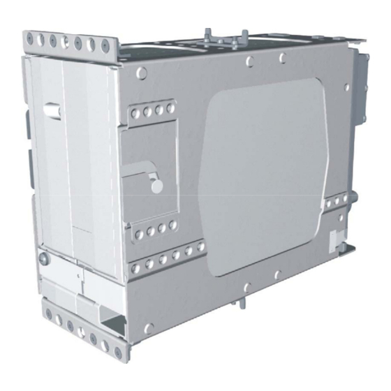
Page 80: Appendix B Outine & Installation Drawings
6.30 160.0 P605 2.9 74 8.35 212.0 8.84 224.6 11.1 12.2 9.23 234.4 9.73 247.2 12.2 11.1 11.1 1.8 46 3.79 96.2 Figure B-1. GIA 63(W) Outline Drawing GIA 63/GIA 63W Installation Manual Page B-1 (Page B-2 blank) 190-00303-05 Revision H... - Page 81 APPENDIX B OUTLINE & INSTALLATION DRAWINGS Figure B-2. GIA 63(W) Installation Drawing GIA 63/GIA 63W Installation Manual Page B-3 (Page B-4 blank) 190-00303-05 Revision H...
-
Page 82: Appendix C Interconnect Examples
APPENDIX C INTERCONNECT EXAMPLES Figure C-1. GIA 63(W) Example Interconnect (Sheet 1 of 7) GIA 63/GIA 63W Installation Manual Page C-1 (Page C-2 blank) 190-00303-05 Revision H... - Page 83 APPENDIX C INTERCONNECT EXAMPLES Figure C-1. GIA 63(W) Example Interconnect (Sheet 2 of 7) GIA 63/GIA 63W Installation Manual Page C-3 (Page C-4 blank) 190-00303-05 Revision H...
- Page 84 APPENDIX C INTERCONNECT EXAMPLES Figure C-1. GIA 63(W) Example Interconnect (Sheet 3 of 7) GIA 63/GIA 63W Installation Manual Page C-5 (Page C-6 blank) 190-00303-05 Revision H...
- Page 85 APPENDIX C INTERCONNECT EXAMPLES Figure C-1. GIA 63(W) Example Interconnect (Sheet 4 of 7) GIA 63/GIA 63W Installation Manual Page C-7 (Page C-8 blank) 190-00303-05 Revision H...
- Page 86 APPENDIX C INTERCONNECT EXAMPLES Figure C-1. GIA 63(W) Example Interconnect (Sheet 5 of 7) GIA 63/GIA 63W Installation Manual Page C-9 (Page C-10 blank) 190-00303-05 Revision H...
- Page 87 APPENDIX C INTERCONNECT EXAMPLES Figure C-1. GIA 63(W) Example Interconnect (Sheet 6 of 7) GIA 63/GIA 63W Installation Manual Page C-11 (Page C-12 blank) 190-00303-05 Revision H...
- Page 88 APPENDIX C INTERCONNECT EXAMPLES Figure C-1. GIA 63(W) Example Interconnect (Sheet 7 of 7) GIA 63/GIA 63W Installation Manual Page C-13 (Page C-14 blank) 190-00303-05 Revision H...
Need help?
Do you have a question about the GIA 63 and is the answer not in the manual?
Questions and answers