Table of Contents
Advertisement
Advertisement
Table of Contents

Subscribe to Our Youtube Channel
Related Manuals for Life Fitness PowerMill


Summary of Contents for Life Fitness PowerMill
- Page 1 Life Fitness PowerMill Climber Assembly Instructions 1008482-0001 REV AA...
- Page 3 EUROPE, MIDDLE EAST, & AFRICA Spain Hong Kong (EMEA)Netherlands & Luxemburg Life Fitness IBERIA Life Fitness Asia Pacific LTD Life Fitness Atlantic BV C/Frederic Mompou 5,1º1ª 32/F, Global Trade Square Bijdorpplein 25-31 08960 Sant Just Desvern Barcelona 21 Wong Chuk Hang Road...
- Page 4 User and Service Documents Link Operation Manuals and other Product Information available at https://www.lftechsupport.com/web/document-library/documents https://www.lftechsupport.com/web/document-library/documents https://www.lftechsupport.com/web/document-library/documents https://www.lftechsupport.com/web/document-library/documents https://www.lftechsupport.com/web/document-library/documents https://www.lftechsupport.com/web/document-library/documents Trobareu el manual de funcionament i altra informació de producte a https://www.lftechsupport.com/web/document-library/documents Mae Llawlyfrau Gweithredu a Gwybodaeth Arall am Beiriannau ar gael yn https://www.lftechsupport.com/web/document-library/documents Die Betriebsanleitung und andere Produktinformationen erhalten Sie unter https://www.lftechsupport.com/web/document-library/documents...
-
Page 5: Table Of Contents
Preventive Maintenance Schedule..............23 Specifications Specifications.......................24 © Copyright 2017, Life Fitness, a division of Brunswick Corporation. All Rights Reserved. Columbia Center III - 9525 West Bryn Mawr Ave., Rosemont, IL 60018 847-288-3300 www.lifefitness.com 1008482-0001 AA October 2017 Page 5 of 24... -
Page 6: Getting Started Safety Instructions
Never operate a Life Fitness product if it has a damaged power cord or electrical plug, or if it has been dropped, damaged, or even partially immersed in water. Contact Life Fitness Customer Support Services. - Page 7 Therefore, the user cannot see if anyone or any thing approaches from the rear. For these reasons this unit is designed for use only in a controlled setting. The PowerMill Climber is not designed for use in the home and should not be used in an environment where children or animals might have access.
-
Page 8: Consignes De Sécurité
Avertissement : Gardez une distance d'au moins 1 m (3 pi) derrière et d'au moins 0,3 m (1 pi) de chaque côté du PowerMill Climber. Ne placez pas ce dernier près de murs, meubles ou autres équipements qui pourraient en obstruer l'accès. - Page 9 Cette unité est dès lors uniquement conçue pour être utilisée dans un environnement contrôlé. Le PowerMill Climber n'est pas conçu pour être utilisé à domicile et ne doit en aucun cas être utilisé dans un environnement auquel les enfants ou animaux ont accès.
-
Page 10: Electrical Power Requirements
Electrical Power Requirements The PowerMill with the Integrity and Discover consoles require an AC power supply according to the electrical configurations listed in the chart below. Console Supply Voltage Frequency Output Voltage Output Current Integrity 100 - 240 VAC 50 - 60 Hz... -
Page 11: Product Overview Product Features
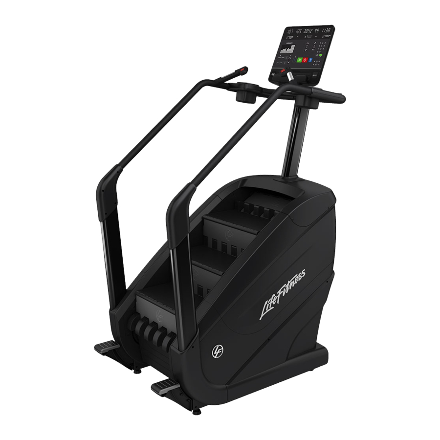
2. Product Overview Product Features Item Description Console Stop / Increase Speed Keypads Contact Heart Rate Sensors Cup Holder Step Assist Wheel Leg Leveler Stop / Decrease Speed Keypads Where to Place Unit Following all Safety Instructions, move the unit to the location in which it will be used. See Specifications for the dimensions of the footprint. -
Page 12: How To Stabilize Unit
How to Stabilize Unit After placing the unit in position, check the unit’s stability by attempting to rock it. Any slight rocking indicates that the unit must be leveled. There are four stabilizing feet on the unit. Check the front and back stabilizing feet to determine which foot does not rest fully on the floor. -
Page 13: Assembly
3. Assembly Hardware and Required Tools Hardware M8 X 35mm SOCKET HEAD CAP SCREW GROMMET M10 X 20mm HEX HEAD CAP SCREW M8 X 16mm BUTTON HEAD CAP SCREW M8 X 18mm HEX WASHER HEAD SCREW M4 X 16mm PHILLIPS PAN HEAD SCREW M4 X 12mm PHILLIPS PAN HEAD SCREW #6 - 16 X PHILLIPS PAN HEAD SCREW M5 X 14mm PHILLIPS PAN HEAD SCREW... -
Page 14: Remove Base From Base Pad
Remove Base from Base Pad Item Description Qty. PowerMill Base Base Pad Install Step Assists Item Description Qty. Step Assist, Left Step Assist, Right M8 X 35mm Socket Head Cap Screw 18-20 ft. lbs. (24.4-27.1 Nm) Install Left and Right Rear Uprights... -
Page 15: Install Console Support Upright
Install Console Support Upright 1. Place top cap gasket on console support upright. 2. Route cables up through console support upright. 3. Secure console support upright to base. Item Description Qty. Console Support Upright Top Cap Gasket M8 x 18mm Hex Washer Head Screw Cables 18-20 ft. -
Page 16: Install Handlebars
3. Slide top cap gasket down the console support upright so it rests flat against the top cover. Install Handlebars 1. Join the left and right rear handlebars to left and right "L" tubes (front handlebars). Secure using screws. Item Description Qty. -
Page 17: Install Accessory Trays
Install Accessory Trays Item Description Qty. M4 X12mm Phillips Pan Head Screw Accessory Tray, Top Right Accessory Tray, Bottom Right Accessory Tray, Top Left Accessory Tray, Bottom Left 10 -12 in. lbs. (1.1 - 1.3 Nm) Install Handlebar Covers Item Description Qty. -
Page 18: Base To Console Cable Connections - Discover / St
Base to Console Cable Connections - Discover / ST Item Description CAT5e Ethernet 24V DC Coax, RG6, Base Ground Wire Base to Console Cable Connections - Integrity Description Console to Base Power Base Signal Left Handlebar Keypad Switch Lifepulse Right Handlebar Keypad Switch Page 18 of 24... -
Page 19: Attach Discover Console
Attach Discover Console 1. Install screws securing middle console shroud to console cover. Item Description Qty. #6-16 X 6 Philips Pan Head Tapping Screw Middle Console Shroud Console Cover 10 - 12 in. lbs. (1.1 - 1.3 Nm) 2. Install screws securing console and console cover to console support upright. Item Description Qty. -
Page 20: Attach Access Panels
Attach Access Panels Item Description Qty. M4 X 12mm Phillips Pan Head Screw Access Panel, Left Access Panel, Right 10 - 12 in. lbs. (1.1 - 1.3 Nm) Tighten Hardware and Verify Leg Leveler Position Tighten all hardware and make sure all leg levelers are down. Item Description Qty. -
Page 21: Remove Line Cord Bracket And Secure Power Cord
Remove Line Cord Bracket and Secure Power Cord 1. Remove line cord bracket and screw. Item Description Qty. Bracket, Line Cord M4 X 12mm Phillips Pan Head Screw 2. Plug in power cord and reattach line cord bracket and screw. Item Description Qty. -
Page 22: Service And Technical Data Preventive Maintenance Tips
4. Service and Technical Data Preventive Maintenance Tips The following preventive maintenance tips will keep the product operating at peak performance: Locate the product in a cool, dry place. Clean the top surface of the steps regularly. Clean the display console and all exterior surfaces with an approved or compatible cleaner (see Approved Cleaners) and a microfiber cloth. -
Page 23: Preventive Maintenance Schedule
Inspect / Adjust Side Hand Rails Clean Inspect Steps Clean Inspect TURN OFF AND UNPLUG THE POWERMILL PRIOR TO PERFORMING THE MAINTENANCE ITEMS BELOW! Clean and lightly Clean / Step Chains Inspect lubricate with 30w oil on Lubricate a cloth. -
Page 24: Specifications Specifications
5. Specifications Specifications Designed Use Heavy / Commercial Maximum User Weight 400 lbs. / 181 kg Ceiling Height Minimum 9 ft. / 2.7 m Usable Step Surface Area 205 sq. in. (520.7 cm) Integrity: 100 - 240 volts, 50/60 Hz, 3 Amps Power Requirements Discover / ST: 100 - 240 volts, 50/60 Hz, 5 Amps Internet...
Need help?
Do you have a question about the PowerMill and is the answer not in the manual?
Questions and answers