Table of Contents
Advertisement
Quick Links
Air Conditionin g & Heatin g
1 Day Programmable
g
Di
ital Thermostat
Multi Stage 2+1
Owner's Manual
Owner's Manual
Owner's Manual
Owner's Manual
Installation Instructions
Installation Instructions
Installation Instructions
Installation Instructions
Thank goodness for Goodman.
and
and
and
and
Model TSTATG2111-2
RESIDENTIAL
TM
Advertisement
Table of Contents

Related Manuals for Goodman TSTATG2111-2


Summary of Contents for Goodman TSTATG2111-2
- Page 1 Model TSTATG2111-2 RESIDENTIAL Air Conditionin g & Heatin g 1 Day Programmable ital Thermostat Multi Stage 2+1 Owner’s Manual Owner’s Manual Owner’s Manual Owner’s Manual Installation Instructions Installation Instructions Installation Instructions Installation Instructions Thank goodness for Goodman.
- Page 3 (1) this device may not cause harmful interference, and (2) this device must accept any interference received, including interference that may cause undesired operation. Thermostat TSTATG2111-2 Tested to Comply with FCC Standards FOR HOME OR OFFICE USE...
- Page 5 Glossary of Terms Auto-Changeover: A mode in which the thermostat will turn on the heating or cooling based on room temperature demand. Cool Setpoint: The warmest temperature that the space should rise to before cooling is turned on (without regard to deadband). Deadband: The number of degrees the thermostat will wait, once a setpoint has been reached, before energizing heating or cooling.
-
Page 7: Table Of Contents
Table of Contents Get to Know Your Thermostat Quick Start INSTALLATION INSTRUCTIONS Sample Wiring Diagrams Test Operation USER SETUP Backlight Operation Scrolling Display Options Thermostat Display Options Emergency Heat Wireless Accessories System Runtimes Time Period Programming INSTALLER SETUP Program Mode Operation Cycles Per Hour Dry Contact Operation Factory Defaults... -
Page 9: Get To Know Your Thermostat
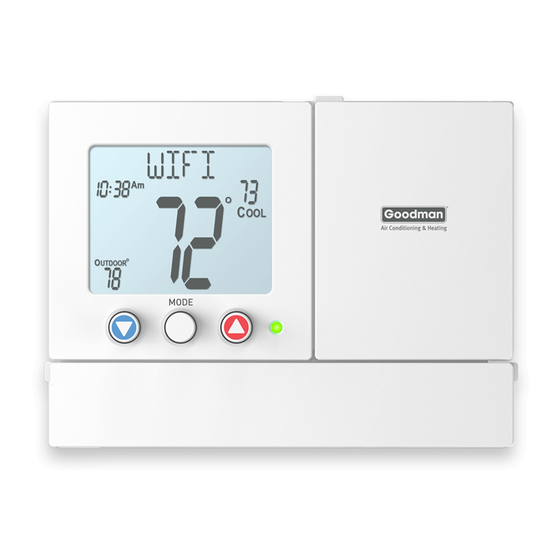
Get to Know Your Thermostat Front Panel Backlit LCD Display HUMIDITY MODE YOUR NAME Scrolling Display 10:38 PROGRAM OUTDOOR HOLD TO SET Outdoor Heat or Cool OVERRIDE MODE Demand Indicator Red = Heat Green = Cool EMERGCY EMERGCY SET CLOCK HOLIDAY DISPLAY ACCESSORY SETUP RST FLTR... - Page 10 Get to Know Your Thermostat Display Features Program On 18:88 Setup Step Stage Fan On Outdoor The scrolling display will be used to help you easily navigate the setup screens in the thermostat. Clock Indicates the current time. This clock is also used to program the time period schedule.
- Page 11 Get to Know Your Thermostat Display Features Program On 18:88 Setup Step Stage Fan On Outdoor Desired Set Temperature Indicates desired room temperature(s). Also displays the highest and lowest temperatures for the day. 2nd Stage icon Indicates what stage of heating is currently energized. Setup Step icon Indicates the step number when the thermostat is in the setup mode.
- Page 12 Get to Know Your Thermostat Display Features Program On 18:88 Setup Step Stage Fan On Outdoor AuxHeat icon Indicates 2nd stage electric strip heat is being used when the thermostat is programmed for Heat Pump operation. Fan On icon Indicates constant, continuous fan operation. When Fan On is not lit - indicates the fan will only operate when necessary to heat or to cool.
-
Page 13: Quick Start
Quick Start During Setup and Programming: Press the UP or DOWN buttons to modify the selection. Press the MODE button to advance and confirm through the setup steps. Setting the Clock MODE Press the SET CLOCK button. Adjust the clock using the UP or DOWN buttons. -
Page 14: Quick Start
Quick Start Selecting Your Desired Temperature AUTO-CHANGEOVER MODE - Pressing the UP or DOWN buttons in Auto or Program mode will adjust both the heat and cool setpoints simultaneously. To adjust heat and cool setpoints individually, choose HEAT mode to adjust the heat setpoint and COOL mode to adjust the cool setpoint, then return to AUTO mode. -
Page 15: Installation Instructions
Installation Instructions Remove & Replace the Old Thermostat To install the thermostat properly, please follow these step by step instructions. If you are unsure about any of these steps, call a qualified technician for assistance. Assemble tools: Flat blade screwdriver, wire cutters and wire strippers. -
Page 16: Wire Connections
Installation Instructions Wire Connections Wire Connections If the terminal designations on your old thermostat do not match those on the new thermostat, refer to the chart below or the wiring diagrams that follow. Install on the Wire from the new thermostat old thermostat Function connector marked... - Page 17 Installation Instructions The TSTATG2111-2 Thermostat Backplate W1/O/B 1st stage heat/reversing valve OUTDOOR Outdoor Sensor connections 2nd stage heat circuit SENSOR Dry Contact 24 VAC common connections CONTACT 24 VAC Return 1st stage compressor Fan relay IMPORTANT: This thermostat requires both R (24 VAC Return) and C (24 VAC Common) be connected to the backplate terminals.
- Page 18 Installation Instructions Explanation of Thermostat Jumpers Jumpers are located on the back of the thermostat RV=O GAS/ELEC RV=O GAS/ELEC ELEC RV=B HEATPUMP ELEC RV=B HEATPUMP GAS/ELEC GAS/ELEC This jumper configures the thermostat to control a conventional gas/electric system or a heat pump. If your system is anything other than a heat pump, leave this jumper set for GAS/ELEC.* HEATPUMP HEATPUMP...
-
Page 19: Sample Wiring Diagrams
Installation Instructions Sample Wiring Diagrams Conventional Heating and Cooling Systems 3 Wire, Heat Only 4 Wire, Cool Only Residential & Commercial 1 Stage Heating Residential & Commercial 1 Stage Cooling. with no Fan. 24VAC Power 24VAC Power 24VAC Common 24VAC Common 1st Stage Cool W1/O/B 1st Stage Heat... - Page 20 Installation Instructions Sample Wiring Diagrams Heat Pump Systems 5 Wire, 1 Stage Cooling, 1 Stage Heat 6 Wire, 1 Stage Cooling, 2 Stage Heat Residential & Commercial Heat Pump with Residential & Commercial Heat Pump with ‘O’ Reversing Valve ‘O’ Reversing Valve 24VAC Power 24VAC Power 24VAC Common...
-
Page 21: Sample Wiring Diagrams
Installation Instructions Sample Wiring Diagrams Dry Contact and Outdoor Sensor 10K Thermistor Outdoor Sensor Condensate Pan Float Switch TSTATGAC-WS Page 13... -
Page 22: Test Operation
Installation Instructions: Test Operation This thermostat has a diagnostic feature that enables testing of all outputs. This feature is contained in Technician Setup. To enter Technician Setup, press and hold the SETUP button for 5 seconds until all the icons appear. Follow the next steps to view settings and test equipment. Press MODE to view the version numbers of the thermostat. -
Page 23: User Setup
User Setup: Backlight Operation How to Change Settings in the Setup Screens To enter Advanced Setup, press the SETUP button, then press MODE. Use the UP or DOWN buttons to adjust the value of your selection. Press MODE to advance to the next setup step. Press SETUP again to leave the setup screens. Backlight (Setup Step 3) The thermostat backlight may be set to be always on, on temporarily with any button press, on throughout the evening, or always off. - Page 24 User Setup: Scrolling Screen and Display Options Scrolling Display Method (Setup Step 17) This option allows the user to choose how the scrolling text is displayed. Options are: Scrolling Non-Scrolling Scroll Letters Slow Whole Words Slow Scroll Letters Fast Whole Words Fast Scroll Words Slow Words Centered Slow Scroll Words Fast...
-
Page 25: Emergency Heat
User Setup Emergency Heat The Emergency Heat function is only available if your thermostat is set to control a Heat Pump. To initiate the Emergency Heat feature, Press and hold the EMERGCY HEAT button for 2 seconds. During Emergency Heat operation the thermostat will turn on the fan and auxiliary stages of heat when there is a demand for heat. - Page 26 User Setup: System Runtimes These setup steps allow the user to monitor equipment runtimes and program service alerts. RUNTIME Runtime hours or days appear in the clock display. Setup Step Service Filter Runtime (Setup Steps 5-6, 12-13) Press the SETUP button, then press MODE repeatedly until the desired setup step appears.
-
Page 27: Time Period Programming
User Setup: Time Period Programming To enter Time Period Programming SET PROGRA screens, Press and hold PROGRAM until the scrolling prompt appears. OFF - Time Period Program is off. RUN - Time Period Program is running. HOLD TO SET - Press and hold PROGRAM to make Time Period HOLD TO SET Programming changes. -
Page 28: Installer Setup
Installer Setup How to Change Settings in the Setup Screens To enter Advanced Setup, press the SETUP button, then press MODE. Use the UP or DOWN buttons to adjust the value of your selection. Press MODE to advance to the next setup step. Press SETUP again to leave the setup screens. Selecting Your Program Mode (Setup Step 1) This thermostat may be configured to be programmable or non-programmable. -
Page 29: Cycles Per Hour
Installer Setup Cycles Per Hour (Setup Step 21) The Cycles Per Hour setting may limit the number of times per hour your HVAC unit may energize. For example, at a setting of 6 cycles per hour the HVAC unit will only be allowed to energize once every 10 minutes. The Cycles Per Hour limit may be overridden and reset by pressing the UP or DOWN buttons on the thermostat. -
Page 30: Factory Defaults
Installer Setup Resetting the Thermostat to the Factory Default Settings (for default values see page 25) If, for any reason, you desire to return all the stored settings back to the factory default settings, follow the instructions below. WARNING: This will reset all Time Period and Advanced Programming to the default settings. -
Page 31: Locking And Unlocking The Keypad
Installer Setup Locking/Unlocking the Keypad To prevent unauthorized use of the thermostat, the front panel buttons may be disabled. To disable, or ‘lock’ the keypad, press and hold the MODE button. While holding the MODE button, press the UP and DOWN buttons together. icon will appear on the display, then release the buttons. -
Page 32: Technician Setup
Technician Setup To enter Technician Setup, press and hold the SETUP button for 5 seconds. After all the icons appear, press MODE. The version number of the thermostat will appear in the scrolling text. Press MODE to advance to the next step. Use the UP or DOWN buttons to adjust the value of your selection. -
Page 33: Advanced Setup Table
Df = Factory Default Setting Advanced Setup Table Range Step# Description Prog Mode Non,1 Available Modes Heat/Cool/Auto/Off, Heat/Cool/ Heat/Cool/Off,Heat/Off, Auto/Off Cool/Off Backlight On,Off,6pm-6am Backlight Level Off-7 levels of brightness Level 5 Current Service Filter Runtime Hours 0-1999 Current Service Filter Calendar Days 0-1999 Current UV Lamp Calendar Days 0-1999... -
Page 34: Troubleshooting
TroubleShooting SYMPTOM: The air conditioning does not attempt to turn on. CAUSE: The compressor timer lockout may prevent the air conditioner from turning on for a period of time. REMEDY: Consult the Owner's Manual in the Installer Setup section to defeat the Cycles Per Hour (page 21). SYMPTOM: The display is blank. -
Page 35: Index
Index program, 1, 19 reset filter, 1, 6 set clock, 1, 5 setup, 1, 15, 20 up (warmer), 1, 5 Alerts programming, 19 see Runtime setting, 19 Accessory, 17 Differential Auto heat and cool, 21 adjust temperature, 6 changeover, 6, 20 fan, 6 Disabled Keypad see Keypad Lockout... - Page 36 Index Heat 1st stage deadband, see Deadband emergency heat, Keypad Lockout, 23 Factory Defaults caution, i electric strip heat, settings, 25 electric/heat resetting, 22 Fahrenheit, 21 pump, indicator, 1 mode, 2, 5 button function, see setpoint, 6, 19 Buttons LCD, 1 on during heat, see Heat Pump Electric Heat...
- Page 37 Index pan, see Dry Contact Programming a Daily UV light, see Reset Schedule, 19 Set Clock, see Clock Setpoint cool, see Cool Non-Programmable heat, see Heat Thermostat, 20 Simplest Operation, 5 Normally Reset Open/Closed, thermostat settings, dry contact, 21 see Factory Defaults runtime fan/filter, 18 Technician Setup, 14,...
- Page 38 Warranty Five-Year Warranty - This Product is warranted to be free from defects in material and workmanship. If it appears within five years from the date of original installation, whether or not actual use begins on that date, that the product does not meet this warranty, a new or remanufactured part, at the manufacturer’s sole option to replace any defective part, will be provided without charge for the part itself provided the defective part is returned to the distributor through a qualified servicing dealer.
- Page 39 Notes: Printed on recycled paper. P/N 88-890 Rev. 1...
Need help?
Do you have a question about the TSTATG2111-2 and is the answer not in the manual?
Questions and answers