Table of Contents
Advertisement
Table of Contents
1.
Introduction ..................................................................................................................................... 2
2.
Warnings and Cautions.................................................................................................................... 2
3.
Quick Start Guide ............................................................................................................................ 2
4.
Pre-Installation Checkout and Site Survey ...................................................................................... 3
4.1
Pre Installation Checkout ....................................................................................................... 3
4.2
Site Survey ............................................................................................................................. 3
5.
Getting Started ................................................................................................................................ 3
5.1
Parts List ................................................................................................................................. 3
5.2
Recommend Tools .................................................................................................................. 4
5.3
Sensor Array Set Up ............................................................................................................... 4
5.3.1
Install Wind Vane ............................................................................................................... 5
5.3.2
Install Wind Cups ............................................................................................................... 5
5.3.3
Install the Rain Gauge Funnel ............................................................................................ 5
5.3.4
Install Batteries ................................................................................................................... 6
5.3.5
Install Mounting Pole ......................................................................................................... 7
5.5 Best Practices for Wireless Communication ................................................................................. 7
5.6
Display Console ..................................................................................................................... 8
6.
Display Console Operation ............................................................................................................. 9
6.1
Screen Display ........................................................................................................................ 9
6.2
Console Initialization ........................................................................................................... 10
6.2.1
Button Operation .............................................................................................................. 11
6.3
Set Mode .............................................................................................................................. 11
6.3.1
Time Zones ....................................................................................................................... 14
6.4
Barometric Pressure Display ................................................................................................ 15
6.4.1
Viewing Absolute vs. Relative Pressure ........................................................................... 15
6.4.2
Rate of Change of Pressure Graph ................................................................................... 15
6.4.3
Viewing Pressure History ................................................................................................. 16
6.4.4
Relative Pressure Calibration Discussion ......................................................................... 16
6.5
Rain Display ......................................................................................................................... 16
6.5.1
Rain Increments of Measure ............................................................................................ 16
6.5.2
Resetting Rain .................................................................................................................. 16
6.5.3
Increments of Rain Definitions ........................................................................................ 17
6.6
Wind Display ........................................................................................................................ 17
6.7
Temperature Display ............................................................................................................ 17
6.7.1
Wind Chill, Dew Point and Heat Index Display .............................................................. 17
6.8
Alarms .................................................................................................................................. 17
6.8.1
Viewing High and Low Alarms ........................................................................................ 17
6.8.2
Setting High and Low Alarms .......................................................................................... 18
6.9
Max/Min Mode .................................................................................................................... 21
6.9.1
Viewing Max/Min Values ................................................................................................. 21
6.10
Calibration ............................................................................................................................ 22
6.10.1
Calibration Settings ...................................................................................................... 22
6.10.2
Calibration Ranges ....................................................................................................... 23
6.10.3
Calibration Discussion ................................................................................................. 24
6.11
Restoring the Console to Factory Default ............................................................................ 26
6.12
Resynchronize Wireless Sensor ............................................................................................ 26
6.13
Backlight Operation ............................................................................................................. 26
6.13.1
With AC Adapter .......................................................................................................... 26
6.13.2
Without AC Adapter ..................................................................................................... 26
Version 1.0
Weather Station User Manual
Page 1
Advertisement
Table of Contents

Subscribe to Our Youtube Channel
Related Manuals for Ambient Weather WH2902


Summary of Contents for Ambient Weather WH2902
-
Page 1: Table Of Contents
Weather Station User Manual Table of Contents Introduction ............................. 2 Warnings and Cautions........................2 Quick Start Guide ..........................2 Pre-Installation Checkout and Site Survey ..................3 Pre Installation Checkout ....................... 3 Site Survey ..........................3 Getting Started ..........................3 Parts List ..........................3 Recommend Tools ........................ -
Page 2: Introduction
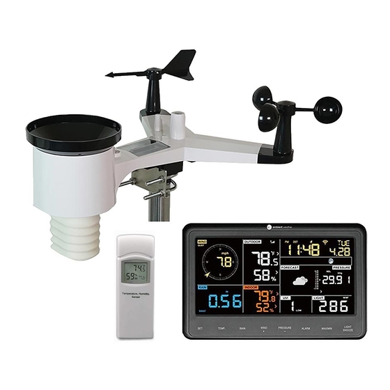
Liability Disclaimer ........................41 FCC Statement .......................... 41 1. Introduction Thank you for your purchase of the Weather WH2902 WiFi OSPREY Solar Powered Wireless Weather Station. The following user guide provides step by step instructions for installation, operation and troubleshooting. -
Page 3: Pre-Installation Checkout And Site Survey
Required Step Description Section Assemble and power up the sensor array Power up the display console and synchronize with sensor array Mount the sensor array 5.3.5 Set date and time on console Calibrate the relative pressure to sea-level conditions (local airport) on console Reset the rain to zero on console 6.5.2... -
Page 4: Recommend Tools
Item Display Console Frame Dimensions (LxWxH): 7.50 x 4.50 x 0.75” LCD Dimensions (LxW): 3.00 x 6.75” Sensor Array Wind Vane 5V DC Adaptor Pole mounting U-bolts Pole mounting U-bolt nuts User manual 5.2 Recommend Tools Precision screwdriver (for small Phillips screw on wind vane and wind cups) ... -
Page 5: Install Wind Vane
5.3.1 Install Wind Vane Reference Figure 2. (a) Locate and align the flat key on the wind vane shaft to the flat key on the wind vane and push the vane on to the shaft. (b) tighten the set screw with a precision screw driver and make sure the wind vane spins freely. -
Page 6: Install Batteries
Figure 4 5.3.4 Install Batteries Reference Figure 5. Insert 3 x AA non-rechargeable batteries (not included) into the battery compartment. The LED indicator on the back of the transmitter will turn on for four seconds, and then flash once every 16 seconds (the sensor transmission update period). Figure 5 Note: If the LED does not light up, or stays on permanently, make sure the battery polarity is correct, or the batteries are fresh. -
Page 7: Install Mounting Pole
5.3.5 Install Mounting Pole Reference Figure 6. The mounting assembly includes two U-Bolts and a bracket that tightens around a 1 to 2” diameter pole (not included) using the four U-Bolt nuts. Figure 6 Use the bubble level next to the rain sensor to make sure the sensor array is completely level. If the sensor array is not level, the rain gauge will not measure properly. -
Page 8: Display Console
The following is a table of reception loss vs. the transmission medium. Each “wall” or obstruction decreases the transmission range by the factor shown below. Medium RF Signal Strength Reduction Glass (untreated) 5-15% Plastics 10-15% Wood 10-40% Brick 10-40% Concrete 40-80% Metal 90-100%... -
Page 9: Display Console Operation
Figure 8 Reference Figure 8 (1). Connect the display console power jack to AC power with the power adapter (included), (2) unfold the desk stand, and place 5 to 10 feet from the sensor array, and wait several minutes for the remote sensors to synchronize with the display console. 6. -
Page 10: Console Initialization
Description Description Time Rainfall Moon phase Outdoor temperature Barometric Pressure Outdoor humidity Weather forecast RF icon UV index Indoor humidity Solar Radiation Indoor temperature Wind speed Date Wind direction WIFI icon MAX/MIN Daily 6.2 Console Initialization After the console is connected to AC power, the console will display the software version number two seconds after power up. -
Page 11: Button Operation
6.2.1 Button Operation Figure 12 The console has 8 buttons at the bottom for easy operation: Description Press and hold to enter the SET mode. Press to switch between Outdoor Temperature, Wind Chill, Heat TEMP. Index, Dew Point. To bypass RF reception, press and hold while powering up the ... - Page 12 press (do not hold) the SET button. To exit the SET mode at any time, press the LIGHT / SNOOZE button. Figure 13 summarizes the set mode sequence and commands. Version 1.0 Page 12...
- Page 13 Command Mode Settings Image Enter Set Press [WIND +] to switch OFF and [SET] + 2 Mode, Beep seconds On or Off This will prevent the beep from sounding when pressing any button. Clear Max/Min Press [WIND +] to switch OFF and [SET] When set to ON, the minimum and maximum values reset every day at...
-
Page 14: Time Zones
Relative Press [WIND +] or [PRESSURE -] to [SET] Pressure adjust relative pressure up or down Calibration Reference Section 6.4.4 for details on calibration of relative pressure. Light Units of Press [WIND +] to change light units [SET] Measure of measure between lux, fc, or w/m2 Temperature Press [WIND +] to change [SET]... -
Page 15: Barometric Pressure Display
Hours from Time Zone Cities 0 GMT: Greenwich Mean London, England WET: Western European 1 CET: Central European Paris, France 2 EET: Eastern European Athens, Greece 3 BT: Baghdad Moscow, Russia 4 --- Abu Dhabi, UAE 5 --- Tashkent 6 --- Astana 7 --- Bangkok... -
Page 16: Viewing Pressure History
Figure 15 6.4.3 Viewing Pressure History Press the [PRESSURE -] button to view the 12 hour, 24 hour, 48 hour and 72 hour pressure average. 6.4.4 Relative Pressure Calibration Discussion To compare pressure conditions from one location to another, meteorologists correct pressure to sea-level conditions. -
Page 17: Increments Of Rain Definitions
Resetting the total rain also resets the monthly, weekly and daily rain. 6.5.3 Increments of Rain Definitions Rain rate is defined as the last 10 minutes of rainfall, multiplied by six (10 minutes x 6 = 1 hour). This is also referred to as instantaneous rain per hour. ... -
Page 18: Setting High And Low Alarms
6.8.1.1 Rain Alarm While the High Alarm is displayed (reference Section 6.8.1), press the RAIN button to display the rain rate and daily rain alarm values. 6.8.1.2 Wind Alarm While the High Alarm is displayed (reference Section 6.8.1), press the WIND button to display the wind speed and wind gust alarm values. - Page 19 Command Mode Settings Enter Alarm Set Mode, Alarm Press [WIND +] or [PRESSURE -] to adjust alarm [ALARM] Hour hour up or down. seconds Press [ALARM] to turn the time alarm on or off. When the alarm is on, the alarm time icon will appear.
- Page 20 Alarm Low Indoor Humidity Press [WIND +] or [PRESSURE -] to adjust alarm [SET] value up or down. Press [ALARM] to turn the alarm on. The alarm icon will appear. Press [ALARM] to turn the alarm off. The alarm icon will disappear. Alarm High Outdoor Press [WIND +] or [PRESSURE -] to adjust alarm [SET]...
-
Page 21: Max/Min Mode
Alarm High Wind Speed Press [WIND +] or [PRESSURE -] to adjust alarm [SET] value up or down. Press [ALARM] to turn the alarm on. The alarm icon will appear. Press [ALARM] to turn the alarm off. The alarm icon will disappear. Alarm High Wind Gust Press [WIND +] or [PRESSURE -] to adjust alarm [SET]... -
Page 22: Calibration
To return to normal mode, press the ALARM button again. Figure 18 6.9.1.1 Display Wind Chill, Heat Index vs. Dew Point Max/Min Values While the max values are displayed as outlined in Section 6.9.1, press the TEMP button once to view the heat index, twice to view the dew point, and a third time to return to outdoor temperature. -
Page 23: Calibration Ranges
Figure 19 Figure 20 summarizes the set mode sequence and commands. Command Mode Settings TEMP. and Enter Calibration Press [WIND +] or [PRESSURE -] to adjust the indoor Mode, Indoor temperature up or down. MAX/MIN Temperature + 5 seconds To restore to factory default, press [ALARM]. Indoor Humidity Press [WIND +] or [PRESSURE -] to adjust the indoor [SET]... -
Page 24: Calibration Discussion
Parameter Range Indoor Temperature ± 9 °F Indoor Humidity ± 9% Outdoor Temperature ± 9 °F Outdoor Humidity ± 9% Absolute Pressure ± 10 hpa (± 2.95 inHg) Wind Direction ± 180 ° Wind Speed Factor 0.5 to 1.5 Rain Factor 0.5 to 1.5 Figure 21 6.10.3 Calibration Discussion... - Page 25 (2) Humidity is a difficult parameter to measure electronically and drifts over time due to contamination. In addition, location has an adverse affect on humidity readings (installation over dirt vs. lawn for example). Official stations recalibrate or replace humidity sensors on a yearly basis. Due to manufacturing tolerances, the humidity is accurate to ±...
-
Page 26: Restoring The Console To Factory Default
6.11 Restoring the Console to Factory Default To restore the console to factory default, perform the following steps: 1. Remove the power from the console by removing the batteries and disconnecting the AC adapter. 2. Apply power by connecting the AC adapter. 3. -
Page 27: Weather Forecasting
No signal loss Lost signal once Figure 24 6.16 Weather Forecasting The five weather icons are Sunny, Partly Cloudy, Cloudy, Rainy and Stormy. The forecast icon is based on the rate of change of barometric pressure. Please allow at least one month for the weather station to learn the barometric pressure over time. -
Page 28: Live Internet Publishing
7. Live Internet Publishing The WS-2902 sends data to three free hosting services: Hosting Service Website Description Weather Undergound WeatherUndeground.com Weather Underground is a free weather hosting service that allows you to send and view your weather station data real-time, view graphs and gauges, import text data for more detailed analysis and use iPhone, iPad and Android applications available at... - Page 29 Figure 26 3. Make sure your mobile device is connected to your WiFi network. Enter the password for your router, and select Save, as shown in Figure 27. Version 1.0 Page 29...
- Page 30 Figure 27 4. Reference Figure 28. If the WiFi icon is not flashing rapidly, (1) press and hold the RAIN and ALARM buttons at the same time for four seconds. (2) The WiFi icon will begin flashing rapidly, indicating the console is searching for your WiFi network. Version 1.0 Page 30...
- Page 31 Figure 28 5. Once the console has connected to your WiFi network, the devices Mac address and IP address will be displayed, as shown in Figure 29. Version 1.0 Page 31...
- Page 32 Figure 29 6. Enter your Wunderground.com and WeatherCloud.net Station ID, Password and StationNum (see Section 8). Version 1.0 Page 32...
-
Page 33: Registering With Weatherunderground.com, Weatherbug.com And Weathercloud.net
Figure 30 8. Registering with WeatherUnderground.com, WeatherBug.com and WeatherCloud.net 8.1 WeatherUnderground.com Visit Wunderground.com and select the Join link at the top of the page. Select the Free sign up option. Figure 31 1. Select More | Register Your PWS. Version 1.0 Page 33... - Page 34 2. Click Send Validation Email. Respond to the validation email from Wunderground (it may take a few minutes). Figure 32 3. Select More | Register Your PWS again and enter all of the information requested. Figure 33 4. After registering your station, make a note of the following: ...
-
Page 35: Weatherbug.com
Figure 34 Note: Your station ID will have the form: KSSCCCC###, where K is for USA station (I for international), SS is your state, CCCC is your city and ### is the station number in that city. In the example above, KAZPHOEN424 is in the USA (K), State of Arizona (AZ), City of Phoenix (PHOEN) and #424. -
Page 36: Weathercloud
Enter the Publisher ID (ID), Password and Station Number (StationNum) into the WS Tool. 8.3 WeatherCloud 1. Visit WeatherCloud.net and enter a Username, Email and Password. Figure 36 2. Respond to the validation email from WeatherCloud (it may take a few minutes). Figure 37 3. - Page 37 Term Definition Accuracy Accuracy is defined as the ability of a measurement to match the actual value of the quantity being measured. Barometer A barometer is an instrument used to measure atmospheric pressure. Calibration Calibration is a comparison between measurements – one of known magnitude or correctness of one device (standard) and another measurement made in as similar a way as possible with a second device (instrument).
-
Page 38: Specifications
Term Definition Hygrometer A hygrometer is a device that measures relative humidity. Relative humidity is a term used to describe the amount or percentage of water vapor that exists in air. Inches of Pressure in Imperial units of measure. Mercury 1 inch of mercury = 33.86 millibars (inHg) Rain Gauge... -
Page 39: Measurement Specifications
10.2 Measurement Specifications The following table provides the specifications for the measured parameters. Measurement Range Accuracy Resolution Indoor Temperature 14 to 140 °F ± 2 °F 0.1 °F Outdoor Temperature -40 to 149 °F (lithium ± 2 °F 0.1 °F batteries) -23 to 140 °F (alkaline batteries) -
Page 40: Troubleshooting Guide
environmental challenges. 4. In snowy environments, spray the top of the weather station with anti-icing silicon spray to prevent snow build up. 12. Troubleshooting Guide Problem Solution Outdoor sensor array The sensor array may have initiated properly and the data is registered by the does not communicate console as invalid, and the console must be reset. -
Page 41: Liability Disclaimer
Problem Solution 2. Confirm your station ID is correct. The station ID is all caps, and the most common issue is substituting an O for a 0 (or visa versa). Example, KAZPHOEN11, not KAZPH0EN11 3. Make sure the date and time is correct on the console. If incorrect, you may be reporting old data, not real time data. - Page 42 2. This device must accept any interference received, including interference that may cause undesired operation. Statement according to FCC part 15.21: Any changes or Modifications not expressly approved by this company could void the user's authority to operate the equipment. Statement according to FCC part 15.105: NOTE: This equipment has been tested and found to comply with the limits for a Class B digital device, pursuant to Part 15 of the FCC Rules.
Need help?
Do you have a question about the WH2902 and is the answer not in the manual?
Questions and answers