U-Line 2224BEV User Manual & Service Manual
2000 series 24" beverage center
Hide thumbs
Also See for 2224BEV:
- User manual (39 pages) ,
- User manual & service manual (70 pages) ,
- User manual (38 pages)
Table of Contents
Advertisement
Quick Links
Download this manual
See also:
User Manual
USER GUIDE & SERVICE MANUAL
SAFETY • INSTALLATION & INTEGRATION • OPERATING INSTRUCTIONS • MAINTENANCE • SERVICE
RIGHT PRODUCT. RIGHT PLACE. RIGHT TEMPERATURE. SINCE 1962.
2000 Series
2224BEV
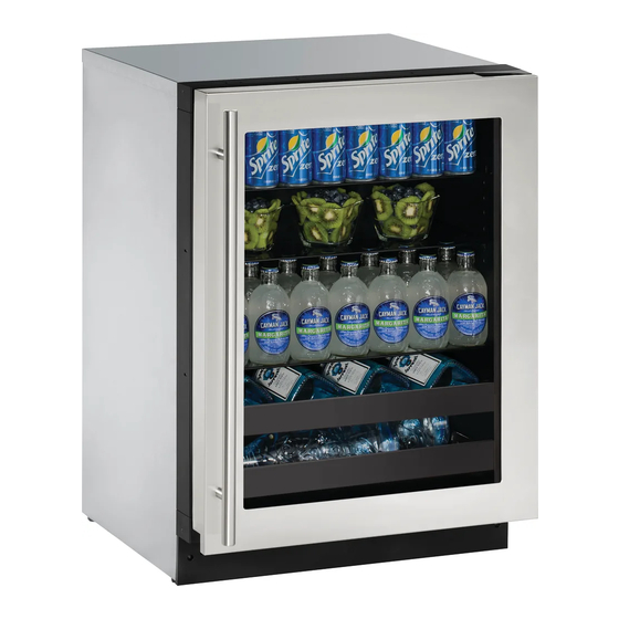
24" Beverage Center
•
•
SAFETY • INSTALLATION & INTEGRATION • OPERATING INSTRUCTIONS • MAINTENANCE • SERVICE
Contents
Safety
Safety and Warning
Intro
Advertisement
Table of Contents
Troubleshooting

Related Manuals for U-Line 2224BEV


Summary of Contents for U-Line 2224BEV
- Page 1 USER GUIDE & SERVICE MANUAL SAFETY • INSTALLATION & INTEGRATION • OPERATING INSTRUCTIONS • MAINTENANCE • SERVICE RIGHT PRODUCT. RIGHT PLACE. RIGHT TEMPERATURE. SINCE 1962. 2000 Series 2224BEV 24" Beverage Center • • SAFETY • INSTALLATION & INTEGRATION • OPERATING INSTRUCTIONS • MAINTENANCE • SERVICE...
- Page 2 Maintenance WELCOME TO U-LINE Congratulations on your U-Line purchase. Your product comes from a company with over five decades of premium modular ice making, refrigeration, and wine preservation experience. U-Line continues to be the American leader, delivering versatility and flexibility for multiple applications including residential, light commercial, outdoor and marine...
-
Page 3: Product Information
1. U-Line Customer Care must be contacted immediately at +1.800.779.2547. 2. Service or repairs performed on the unit without prior written approval from U-Line is not permitted. If the unit has been altered or repaired in the field without prior written approval from U-Line, claims will not be eligible. -
Page 4: Safety And Warning
USER GUIDE SAFETY • INSTALLATION & INTEGRATION • OPERATING INSTRUCTIONS • MAINTENANCE • SERVICE Safety and Warning User Guide. Do not damage the refrigerant circuit. NOTICE WARNING Please read all instructions before installing, operating, or servicing the appliance. Service must be done by factory authorized service personnel. -
Page 5: Disposal And Recycling
USER GUIDE u-line.com Disposal and Recycling DANGER RISK OF CHILD ENTRAPMENT. Before you throw away your old refrigerator or freezer, take off the doors and leave shelves in place so children may not easily climb inside. If the unit is being removed from service for disposal,... -
Page 6: Environmental Requirements
USER GUIDE u-line.com SAFETY • INSTALLATION & INTEGRATION • OPERATING INSTRUCTIONS • MAINTENANCE • SERVICE Environmental Requirements This model is intended for indoor/interior applications only and is not to be used in installations that are open/ exposed to natural elements. - Page 7 USER GUIDE u-line.com SAFETY • INSTALLATION & INTEGRATION • OPERATING INSTRUCTIONS • MAINTENANCE • SERVICE Electrical WARNING SHOCK HAZARD — Electrical Grounding Required. Never attempt to repair or perform maintenance on the unit until the electricity has been disconnected. Never remove the round grounding prong from the plug and never use a two-prong grounding adapter.
-
Page 8: Cutout Dimensions
Electrical 1 Cutout Dimensions PREPARE SITE Your U-Line product has been designed exclusively for a built-in installation. When built-in, your unit does not require additional air space for top, sides, or rear. However, the front grille (plinth strip/base fascia) must NOT be obstructed. -
Page 9: Product Dimensions
USER GUIDE u-line.com SAFETY • INSTALLATION & INTEGRATION • OPERATING INSTRUCTIONS • MAINTENANCE • SERVICE Cutout Dimensions 1 Product Dimensions... -
Page 10: Side-By-Side Installation
USER GUIDE u-line.com SAFETY • INSTALLATION & INTEGRATION • OPERATING INSTRUCTIONS • MAINTENANCE • SERVICE Product Dimensions 1 Side-by-Side Installation Hinge-by-Hinge Installation (Mullion) When installing two units hinge-by-hinge, 13/16" (22 OTHER SITE REQUIREMENTS mm) is required for integrated models. Additional... -
Page 11: Anti-Tip Bracket
USER GUIDE u-line.com SAFETY • INSTALLATION & INTEGRATION • OPERATING INSTRUCTIONS • MAINTENANCE • SERVICE Side-by-Side Installation 1 Anti-Tip Bracket CAUTION The anti-tip bracket must be installed to prevent the unit from tipping when doors are fully opened or excess weight is placed on the front of the unit. -
Page 12: General Installation
USER GUIDE u-line.com SAFETY • INSTALLATION & INTEGRATION • OPERATING INSTRUCTIONS • MAINTENANCE • SERVICE Anti-Tip Bracket 1 unit’s top surface should be approximately 1/8" (3 General Installation mm) below the countertop. 4. Install the anti-tip bracket. 5. Remove the interior packing material and wipe out the inside of the unit with a clean, water- dampened cloth. - Page 13 3. Apply double sided tape to the backside of the integrated grill (plinth strip/base fascia). Use the diagram below for reference. U-Line recommends ™ ™ tape, a high strength bonding tape. Apply Tape To Shaded Area 4.
-
Page 14: Grille - Plinth Installation
USER GUIDE u-line.com SAFETY • INSTALLATION & INTEGRATION • OPERATING INSTRUCTIONS • MAINTENANCE • SERVICE Grille - Plinth Installation REMOVING AND INSTALLING GRILLE (PLINTH STRIP/BASE FASCIA) WARNING Disconnect electric power to the unit before removing the grille (plinth strip/base fascia). -
Page 15: Door Swing
USER GUIDE u-line.com SAFETY • INSTALLATION & INTEGRATION • OPERATING INSTRUCTIONS • MAINTENANCE • SERVICE Door Swing For Integrated models that are installed adjacent to a wall, 1/4" (6 mm) clearance is recommended from wall on hinge side to allow the door to open 90°. Allow for additional space for any knobs or pulls installed on the integrated panel/frame. - Page 16 USER GUIDE u-line.com SAFETY • INSTALLATION & INTEGRATION • OPERATING INSTRUCTIONS • MAINTENANCE • SERVICE...
- Page 17 USER GUIDE u-line.com SAFETY • INSTALLATION & INTEGRATION • OPERATING INSTRUCTIONS • MAINTENANCE • SERVICE Integrated Stainless...
- Page 18 3. Once cover is removed, slide hinge pin into hole as shown. Pin should slide into place, stopping the Your U-Line unit was shipped to you with the optional door at 90°; if the pin does not go into the hole 90°...
-
Page 19: Door Alignment And Adjustment
USER GUIDE u-line.com SAFETY • INSTALLATION & INTEGRATION • OPERATING INSTRUCTIONS • MAINTENANCE • SERVICE Door Stop 1 Door Adjustments DOOR ALIGNMENT AND ADJUSTMENT Align and adjust the door if it is not level or is not sealing properly. If the door is not sealed, the unit may not cool properly, or excessive frost or condensation may form in the interior. - Page 20 USER GUIDE u-line.com SAFETY • INSTALLATION & INTEGRATION • OPERATING INSTRUCTIONS • MAINTENANCE • SERVICE Door Adjustments 1...
- Page 21 USER GUIDE u-line.com SAFETY • INSTALLATION & INTEGRATION • OPERATING INSTRUCTIONS • MAINTENANCE • SERVICE 3. Using T-25 Torx bit loosen screw #1 and remove screw #2 on top and bottom hinge. Slide and remove the door from unit. Completely remove screw #1 on top and bottom.
-
Page 22: Wood Trim Finishing
Not following this warning may cause the inner liner of the unit to have a permanent odor, which the warranty will not cover. U-Line recommends Minwax ® Brand Water Based Stains and Minwax Polycrylic ®... - Page 23 USER GUIDE u-line.com SAFETY • INSTALLATION & INTEGRATION • OPERATING INSTRUCTIONS • MAINTENANCE • SERVICE Wood Trim Finishing 1...
-
Page 24: First Use
USER GUIDE u-line.com SAFETY • INSTALLATION & INTEGRATION • OPERATING INSTRUCTIONS • MAINTENANCE • SERVICE First Use All U-Line controls are preset at the factory. Initial startup requires no adjustments. NOTICE U-Line recommends allowing the unit to run overnight before loading with product. -
Page 25: Control Operation
USER GUIDE u-line.com SAFETY • INSTALLATION & INTEGRATION • First Use 1 OPERATING INSTRUCTIONS • MAINTENANCE • SERVICE Control Operation CONTROL FUNCTION GUIDE FUNCTION COMMAND DISPLAY/OPTIONS ON/OFF Unit will immediately turn ON or OFF. Press and release Press and release to leave interior Toggle lights Glass door wine and beverage centers only. - Page 26 The unit will still maintain internal temperatures and set points. View a full list of Star-K certified U-Line units at www.star- k.org. To enable Sabbath Mode: 1. Press...
- Page 27 USER GUIDE u-line.com SAFETY • INSTALLATION & INTEGRATION • Sabbath Mode 1...
-
Page 28: Airflow And Product Loading
Do not install the unit behind a door. When properly loaded, your U-Line unit will store up to 123 (12 oz. [330 ml]) cans or 79 (12 oz. [330 ml]) bottles and 10 (750 ml) bottles of wine. -
Page 29: U-Line Wine Guide
Zinfandel, Cabernet French Rhone, Chateauneuf-du- Fish, Shell Fish, Crab, Dry White Wines, Light Italian Pape Barbaresco, Barolo Oysters Sparkling or Extra Dry Champagne Medium-Bodied Dry California Pinot Noir Bordeaux, French Burgundy Beef, Venison Full-Bodied Red Wines U-Line Wine Guide 1... -
Page 30: Ideal Wine Storage Considerations
Myth 4: Wine color does not change with aging. Common Tasting Terms IDEAL WINE STORAGE CONSIDERATIONS Terminology Description Acidity A critical element of wine that is responsible for preserving the wines freshness. Excess acidity results in an overly tart and sour wine. U-Line Wine Guide 2... - Page 31 Wines can become flat or tired when voids and vacuums are created inside the wine bottle. In order to create voids and vacuums within a liquid, aggressive motion or shaking of the wine bottle would have to occur. U-Line Wine Guide 3...
- Page 32 Approximately 45°F (7°C) Sparkling Wine Captain Models - A Touch of Elegance ® In 1985 U-Line was the first North American appliance manufacturer to develop a residential wine storage unit, the Wine Captain ® . Each U-Line Wine Captain ®...
-
Page 33: Recommended Wine Storage
U-Line recommends arranging wine bottles as shown in the illustrations below. NOTE: After stocking, allow unit to stabilize product temperatures for 24 hours. -
Page 34: Interior Shelves
USER GUIDE u-line.com SAFETY • INSTALLATION & INTEGRATION • OPERATING INSTRUCTIONS • MAINTENANCE • SERVICE Recommended Wine Storage 1 CAUTION Interior Shelves Clips MUST be installed with the ribbed side REMOVING AND INSTALLING GLASS SHELVES down. Failure to do so may result in shelf or unit damage. -
Page 35: Exterior Cleaning
USER GUIDE u-line.com Cleaning INTERIOR CLEANING Disconnect power to the unit. EXTERIOR CLEANING Stainless Models Clean the interior and all removed components using Stainless door panels and handles can discolor when a mild nonabrasive detergent and warm water exposed to chlorine gas, pool chemicals, saltwater or solution applied with a soft sponge or non-abrasive cleaners with bleach. - Page 36 USER GUIDE u-line.com SAFETY • INSTALLATION & INTEGRATION • OPERATING INSTRUCTIONS • • SERVICE MAINTENANCE NOTICE The drain pan was not designed to capture the water created when manually defrosting. To prevent water from overflowing the drain pan and possibly damaging water sensitive flooring, the unit must be removed from cabinetry.
-
Page 37: Cleaning Condenser
USER GUIDE u-line.com SAFETY • INSTALLATION & INTEGRATION • OPERATING INSTRUCTIONS • MAINTENANCE • SERVICE Cleaning 2 Cleaning Condenser INTERVAL - EVERY SIX MONTHS To maintain operational efficiency, keep the front grille (plinth strip/base fascia) free of dust and lint, and clean the condenser when necessary. -
Page 38: Wine Rack Installation
USER GUIDE u-line.com SAFETY • INSTALLATION & INTEGRATION • OPERATING INSTRUCTIONS • MAINTENANCE • SERVICE Wine Rack Installation To clean wine racks: 1. Saturate a soft cloth with a soapy, warm water To remove wine racks for cleaning: solution. 1. Remove any bottles stored on the rack. - Page 39 If the unit will be exposed to temperatures of 40°F (5°C) or less, the steps above must be followed. For questions regarding winterization, please call U-Line at +1.800.779.2547. CAUTION Damage caused by freezing temperatures is not covered by the warranty.
-
Page 40: Troubleshooting Guide
• Compressor: The compressor makes a hum or pulsing sound that may be heard when it operates. BEFORE CALLING FOR SERVICE If you think your U-Line product is malfunctioning, • Evaporator: Refrigerant flowing through an read the CONTROL OPERATION section to clearly evaporator may sound like boiling liquid. -
Page 41: Checking Product Temperature
E3 indicates the door may be opened too Shows ER or E long. Ensure the door is closing properly. Followed by a For other error codes contact U-Line Avoid opening the unit during the testing period. Number. Customer Service. Troubleshooting 1... -
Page 42: One Year Limited Warranty
• Food, beverage, and medicine loss are not covered by these warranties. • If the product is located in an area where U-Line factory authorized service is not available, you may be responsible for a trip charge or you may be required to bring the product to a U-Line factory authorized service location at your own cost and expense. -
Page 43: Wire Diagram
USER GUIDE u-line.com SAFETY • INSTALLATION & INTEGRATION • OPERATING INSTRUCTIONS • MAINTENANCE • SERVICE Copyright © 2014/2017 U-Line Corporation. All Rights Reserved. | Publication Number 30379 | 04/2017 Rev. K Warranty 1 Wire Diagram... -
Page 44: Product Liability
The part that caused the damage must be returned to U-Line in its entirety. The part must be clearly labeled with the serial number of the unit it was removed from, the date, and the servicer who removed the part. -
Page 45: Warranty Claims
USER GUIDE u-line.com SAFETY • INSTALLATION & INTEGRATION • OPERATING INSTRUCTIONS • MAINTENANCE • SERVICE Product Liability 1 Warranty Claims • Alternatively, a Proof of Purchase (or equivalent) may submitted with the warranty claim to The following information defines the parameters for... - Page 46 USER GUIDE u-line.com SAFETY • INSTALLATION & INTEGRATION • OPERATING INSTRUCTIONS • MAINTENANCE • SERVICE Warranty Claims 1...
-
Page 48: Ordering Replacement Parts
Some parts will require color or voltage information. If U-Line requires the return of original parts, we will inform you when the parts order is taken. This requirement will be noted on your packing list. A prepaid shipping label will be included with the replacement part. -
Page 49: Refrigeration System Diagnosis Guide
USER GUIDE u-line.com SAFETY • INSTALLATION & INTEGRATION • OPERATING INSTRUCTIONS • MAINTENANCE • SERVICE Ordering Replacement Parts 1 USER GUIDE System Diagnosis Guide REFRIGERATION SYSTEM DIAGNOSIS GUIDE System Suction Suction Compressor Condenser Capillary Evaporator Wattage Condition Pressure Line Discharge... - Page 50 SAFETY • INSTALLATION & INTEGRATION • OPERATING INSTRUCTIONS • MAINTENANCE • SERVICE To ensure the windings are not shorted, check the S Compressor Specifications 1 and R to ground. EMX20CLC Refrigerant R600a Voltage 115 - 127 VAC Frequency 60 Hz Run Cap 12μF/165 VAC...
-
Page 51: Troubleshooting - Extended
USER GUIDE u-line.com SAFETY • INSTALLATION & INTEGRATION • OPERATING INSTRUCTIONS • MAINTENANCE • SERVICE Troubleshooting - Extended NORMAL OPERATING SOUNDS All models incorporate rigid foam insulated cabinets to CAUTION provide high thermal efficiency and maximum sound Never attempt to repair or perform maintenance reduction for its internal working components. -
Page 52: Main Control
USER GUIDE u-line.com SAFETY • INSTALLATION & INTEGRATION • OPERATING INSTRUCTIONS • MAINTENANCE • SERVICE Test overload and relay, replace as needed. Compressor operating - no cooling Refer to System Diagnosis Guide. Evaporator fan not operating Use #19, Component Testing in Service Mode. - Page 53 USER GUIDE u-line.com SAFETY • INSTALLATION & INTEGRATION • OPERATING INSTRUCTIONS • MAINTENANCE • SERVICE compressor will automatically deactivate during Check Voltage Alert Customer No Voltage an overload and will remain deactivated until the At Wall Outlet Of Power Failure overload switch cools.
- Page 54 USER GUIDE u-line.com SAFETY • INSTALLATION & INTEGRATION • OPERATING INSTRUCTIONS • MAINTENANCE • SERVICE Magnet Away From Switch Door Open Switch Open (Switch Closed) Troubleshooting - Extended 4...
- Page 55 USER GUIDE u-line.com SAFETY • INSTALLATION & INTEGRATION • OPERATING INSTRUCTIONS • MAINTENANCE • SERVICE Control Operation - Service UI BUTTON LAYOUT Hidden Button -Accesses Service Menu -No LED directly above. All LEDs turn on with button activation except #7.
-
Page 56: Showroom Mode
USER GUIDE u-line.com SAFETY • INSTALLATION & INTEGRATION • OPERATING INSTRUCTIONS • MAINTENANCE • SERVICE CONTROL FUNCTION QUICK GUIDE FUNCTION COMMAND DISPLAY/OPTIONS ON/OFF Unit will immediately turn ON or OFF Press and release Glass door wine captains and beverage Press... - Page 57 USER GUIDE u-line.com SAFETY • INSTALLATION & INTEGRATION • OPERATING INSTRUCTIONS • MAINTENANCE • SERVICE 5. THERMISTOR 1 — ZONE OFFSET (DO NOT Adjust thermistor #3 offset MAKE AN ADJUSTMENT TO THIS WITHOUT Adjust thermistor #4 offset CONTACTING TECH LINE: 800-779-2547)
- Page 58 USER GUIDE u-line.com SAFETY • INSTALLATION & INTEGRATION • OPERATING INSTRUCTIONS • MAINTENANCE • SERVICE Thermistor 4 open (Does not apply to this DC Output 4 model). DC Output 5 Thermistor 1 shorted. 20. MODEL NUMBER INDICATOR Thermistor 2 shorted.
- Page 59 1. Disconnect the unit from power source. 2. Push and hold the U-Line button. 3. While still holding the U-Line button, plug the unit into the appropriate power source. 4. When the flashing digits appear (3-5 seconds), use the up and down arrow buttons to select the appropriate model number*.
- Page 60 USER GUIDE u-line.com SAFETY • INSTALLATION & INTEGRATION • OPERATING INSTRUCTIONS • MAINTENANCE • SERVICE...
- Page 61 USER GUIDE u-line.com SAFETY • INSTALLATION & INTEGRATION • OPERATING INSTRUCTIONS • MAINTENANCE • SERVICE...
- Page 62 USER GUIDE u-line.com SAFETY • INSTALLATION & INTEGRATION • OPERATING INSTRUCTIONS • MAINTENANCE • SERVICE...
-
Page 63: Thermistor Failure
USER GUIDE u-line.com SAFETY • INSTALLATION & INTEGRATION • OPERATING INSTRUCTIONS • MAINTENANCE • SERVICE Thermistors Thermistor three (Ambient): Located in the base of the unit (secured to the Thermistors are used for various temperature condenser). It is used to monitor the ambient readings. - Page 64 USER GUIDE u-line.com SAFETY • INSTALLATION & INTEGRATION • OPERATING INSTRUCTIONS • MAINTENANCE • SERVICE If the thermistor fails the unit will operate normally. Thermistor 1 Thermistor Resistance Data Nominal Resistance Temp (F) Temp (C) (OHMS)* 169157 121795 88766 65333...
-
Page 65: Remove Fan And Cover
USER GUIDE u-line.com SAFETY • INSTALLATION & INTEGRATION • OPERATING INSTRUCTIONS • MAINTENANCE • SERVICE Thermistor 2 Defrost The models below have automatic or frost free design and do not require manual defrosting under normal conditions. Defrost Settings Base Model... - Page 66 USER GUIDE u-line.com SAFETY • INSTALLATION & INTEGRATION • OPERATING INSTRUCTIONS • MAINTENANCE • SERVICE cycle. Fan delay times can be modified through the 7. Remove internal shelving. service menu. 8. Remove rear shelf clips, fronts can remain. Evaporator fan operation is also determined by door switch state.
- Page 67 USER GUIDE u-line.com SAFETY • INSTALLATION & INTEGRATION • OPERATING INSTRUCTIONS • MAINTENANCE • SERVICE 14.Remove and replace fan. Take special care to properly route fan wire. NOTICE Fan must be oriented to pull air in through lower evaporator cover vents and push air out at fan mounting location.