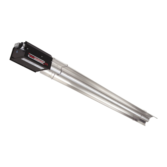
HeatStar ERXL-80 Operating Instructions And Owner's Manual
Gas-fired low-intensity infrared heaters approved
for residential garage / commercial applications erxl series
Hide thumbs
Also See for ERXL-80:
- Operating instructions and owner's manual (84 pages) ,
- Operating instructions manual (84 pages) ,
- Operating instructions and owner's manual (84 pages)
Table of Contents
Advertisement
Available languages
Available languages
Quick Links
READ INSTRUCTIONS CAREFULLY:
Heatstar ERXL
Gas-Fired Low-Intensity Infrared Heaters Approved
For Residential Garage/Commercial Applications
WARNING:
Improper installation, adjustment, alteration, service or maintenance can cause
property damage, injury, or death. Read the installation, operating and maintenance instructions
thoroughly before installing or servicing this equipment.
DO NOT
DO NOT
DO NOT
Do not
FOR YOUR SAFETY:
WARNING:
OPERATING INSTRUCTIONS
X L
AND OWNER'S MANUAL
LANGUAGES INCLUDED
•ENGLISH
•FRENCH
•SPANISH
Advertisement
Table of Contents

Related Manuals for HeatStar ERXL-80


Summary of Contents for HeatStar ERXL-80
- Page 1 OPERATING INSTRUCTIONS AND OWNER’S MANUAL READ INSTRUCTIONS CAREFULLY: Heatstar ERXL LANGUAGES INCLUDED •ENGLISH Gas-Fired Low-Intensity Infrared Heaters Approved •FRENCH For Residential Garage/Commercial Applications •SPANISH WARNING: Improper installation, adjustment, alteration, service or maintenance can cause property damage, injury, or death. Read the installation, operating and maintenance instructions thoroughly before installing or servicing this equipment.
- Page 2 WARNING: WARNING: GENERAL HAZARD WARNING: WARNING: The State of California requires the following warning: CONTENTS SECTION 1:Introduction Checking Shipment Installer Responsibility...
-
Page 3: Critical Considerations
SECTION 2: Planning Hazardous Locations: National Standards and Applicable Critical Considerations Codes Gas Codes: Aircraft Hangers: Public Garages: Venting:... -
Page 4: Erxl
Clearances To Combustibles TABLE 1: Reflector Type Position ERXL-40 ERXL-60 ERXL-80 ERXL-100 ERXL-125 ERXL-150 ERXL-175 WARNING: FIRE OR EXPLOSION HAZARD CAN CAUSE PROPERTY DAMAGE, SEVERE INJURY OR DEATH. - Page 5 Clearances To Combustibles Figure 1: STANDARD REFLECTOR...
- Page 6 SECTION 3: Installation & Assembly...
-
Page 7: Installation Procedure
Installation Procedure DON’T FIGURE 2: Ener-Radiant XL Overview Tube and Reflector Hanger Burner Housing Tube and Reflector Hanger Reflectors Heat Exchange Tubes Turbulator Assembly Tube Coupling Assembly Where Field Changes Occur Vent Adapter... - Page 8 18” 18” 10’ 2-1/2” ALUMINIZED ALUMINIZED 9' Long Turbulator Section FIGURE 2B: Ener-Radiant XL Model ERXL-60, ERXL-80, Assembly Overview 20 ft. Exchanger length. 21 ft. - 4 in. Total Heater length. 4 Suspensin points indicated. HANGER HANGER HANGER HANGER 18”...
- Page 9 FIGURE 2E: Ener-Radiant XL Model ERXL-100, ERXL-125 40 ft. Exchanger length. 41 ft. - 4 in. Total Heater length. 8 Suspension points as indicated. 18" 18" 18" 18" 18" 18" 18" 18” 18” 18” 18” Typ. 10’ 2-1/2” 10’ 2-1/2” 10’...
- Page 10 FIGURE 3: Ener-Radiant XL Dimensions & Suggested Mounting Heights Burner Side View Burner Rear View Burner Ratings and Heat Exchanger Lengths: (NG and LP) Suggested Mounting Heights Typical Heat Exchanger Minimum Suggested Model # Rate (BTU/Hr.) Turbulator Mounting Length Total Length Min.
- Page 11 FIGURE 5: Installation of Elbow & Coupling COUPLING ASSEMBLY Couplings: (38.73 CM) (15.24 CM) 90° FIGURE 4: (1) U-tube, (1) coupling Loosen Install U-tube elbow into (10cm) Tighten Hole 1 Hole 2 Impact 18" Block (45cm) 10" Coupling (25cm) Assembly (43cm) Plain Coupling - 14612 Key for Coupling - 14616...
- Page 12 FIGURE 6: Typical Suspension Details FIGURE 8: Burner Box / Transition Tube Detail Concrete Burner Box Beam I-Beam Truss S-Hook FIGURE 7: Tube and Reflector Hanger FIGURE 9: Reflector End Cap FIGURE 7: Mounting Flange / Tube Detail...
-
Page 13: Engineering Specifications
SECTION 4 Gas pressure at MANIFOLD: Engineering Specifications Natural Gas: 3.5” W.C. LP Gas: 10.5” W.C. A. Burner & Burner Controls Gas INLET pressure: Natural Gas: 4.6” W.C. Min 11.0” W.C. Max LP Gas: 11.0” W.C. Min 14.0” W.C. Max Electrical Rating: Dimensions: Flue Connection Size…………………4”... - Page 14 SECTION 5 Venting / Ducting General Requirements Vertical Venting Common Venting NOTE: Alternative Arrangements / Optional Equipment for Venting Unvented Operation COMMON VENTING - (2) Heaters (Horizontal and Vertical) Horizontal Venting...
- Page 15 FIGURE 12: Common Roof Venting VERTICAL COMMON VENTING Approved Vent Cap Flashing Type "B" Vent required outdoors. SIDE VIEW Roof Secure all joints with 3 (minimum) #8 x 3/8" sheet metal screws and seal all joints. Vent Adapter Stk. #19021 Burner Box Burner Box HORIZONTAL COMMON VENTING...
- Page 16 FIGURE 10: Unvented Operation FIGURE 10b: Double Wall 8"(20cm) to 10"(25cm) Max. 18" (45cm) Min. 3'-0" (91cm) Min. 36” (91cm) 36” (91cm) 6' (182cm) Min. FIGURE 11: Vertical Venting FIGURE 10A: Single Wall 18"(45cm) 18" (45cm) Min. 3'-0" (91cm) Min. 6' (182cm) Min.
-
Page 17: Gas Piping
SECTION 6 Outside Combustion Air Supply Gas Piping IMPORTANT: If the building has a slight negative pressure or contaminants are present in the air, an outside combustion air supply to the heaters is strongly recommended. FIGURE 13: Non-Pressurized Outside Air Supply Duct Outside Air Terminal NOTE:... - Page 18 SECTION 7 FIGURE 18: Ener-Radiant XL Burner Internal Wiring Ladder Diagram Wiring (NEUTRAL) L2 (HOT) 120V White Black Orange Blue Transfomer FIGURE 15: Line Voltage Thermostat Wiring Thermostat Burners (Maximum – 2 per Thermostat) Black Air Switch White Gas Valve White Yellow Yellow...
- Page 19 SECTION 8 Operation & Maintenance Sequence of Operation Troubleshooting Blower Motor Fails to Run Igniter Does Not Glow: Valve Does Not Come On: Maintenance WARNING: Burner Does Not Light:...
- Page 20 Burner Does Not Stay Lit Honeywell Valve LED Status FIGURE 19:...
- Page 21 SECTION 9: Troubleshooting Guide. Ener-Radiant XL START...
- Page 22 Parts List for Ener-Radiant XL Tube Heaters ERXL-40 Item Stock # Description Item Stock# Description ERXL-80 ERXL-60 Item Stock # Description Item Stock# Description...
- Page 23 ERXL-80 Item Stock # Description Item Stock# Description ERXL-100 Item Stock # Description Item Stock# Description...
- Page 24 ERXL-125 ERXL-100 Item Stock # Description Item Stock# Description ERXL-125 / ERXL-150 / ERXL-175 Item Stock # Description Item Stock# Description...
-
Page 25: Table Of Contents
ERXL-150 ERXL-175 Item Stock # Description Item Stock# Description ACCESSORY PARTS LIST INSTALLATION KITS Stock Number Description CONVERSION KITS ERXL-40 ERXL-60 ERXL-80 ERXL-100 ERXL-125 ERXL-150 ERXL175... - Page 26 ITEM# EGI # DESCRIPTION ITEM# EGI # DESCRIPTION ITEM# EGI # DESCRIPTION...
- Page 28 OPERATING INSTRUCTIONS AND OWNER’S MANUAL WARNING: FOR INFORMATION REGARDING SERVICE OR PARTS: FOR ADDITIONAL INFORMATION: LIMITED WARRANTY ANSI Z83.20b-2011 CSA 2.34b-2011...
-
Page 29: Erxl
INSTRUCTIONS D'UTILISATION ET MANUEL DU PROPRIÉTAIRE VEUILLEZ LIRE ATTENTIVEMENT LES INSTRUCTIONS : Heatstar ERXL LANGUES INCLUSES • ANGLAIS Fournaises à infrarouge de faible intensité alimentées • FRANÇAIS au gaz et approuvées pour applications commerciales • ESPAGNOL AVERTISSEMENT : Une installation, un réglage, une modification, une réparation ou un entretien incorrect peut entraîner des dommages matériels, des blessures ou la mort. - Page 30 AVERTISSEMENT : AVERTISSEMENT : AVERTISSEMENT GÉNÉRAL DE DANGER : AVERTISSEMENT : L'État de la Californie exige que l'avertissement suivant soit fourni : SECTION 1 : Présentation CONTENU Vérification de l'expédition Responsabilité de l'installateur...
- Page 31 Emplacements dangereux : SECTION 2 : Planification Considérations critiques Normes nationales et codes applicables Codes du gaz : Hangars d'aéronefs : Garages publics : Aération :...
- Page 32 Espaces libres aux combustibles TABLEAU 1 : Reflector Type Position ERXL-40 ERXL-60 ERXL-80 ERXL-100 ERXL-125 ERXL-150 ERXL-175 AVERTISSEMENT : RISQUES D'EXPLOSION ET D'INCENDIE PEUT PROVOQUER DES DOMMAGES AUX BIENS, DES BLESSURES GRAVES OU MÊME LA MORT.
- Page 33 Espaces libres aux combustibles Figure 1 : STANDARD REFLECTOR...
- Page 34 SECTION 3 : Installation et assemblage...
- Page 35 À FAIRE Procédures d’installation NE PAS FAIRE FIGURE 2 : Aperçu Ener-Radiant XL Support pour tube et réflecteur Bâti du brûleur Support pour tube et réflecteur Réflecteurs Tubes d'échangeur de chaleur Turbulateur Assemblage du couplage du tube Adaptateur d'évent...
- Page 36 10’ 2-1/2” ALUMINIZED FIGURE 2B : Modèle Ener-Radiant Ener-Radiant XL Model ERXL-60, ERXL-80 Longueur de l'échangeur de 6,0 m (20 pi). Longueur totale de la fournaise de 6,4 m (21 pi) - 10 cm (4 po). 4 points de suspension comme indiqué.
- Page 37 FIGURE 2E : Modèle Ener-Radiant Ener-Radiant XL Model ERXL-100, ERXL-125 Longueur de l'échangeur de 12,2 m (40 pi). Longueur totale de la fournaise de 12,5 m (41 pi) - 10 cm (4 po). 8 points de suspension comme indiqué. 18" 18" 18"...
- Page 38 FIGURE 3 : Dimensions et hauteurs de montage suggérées du Ener-Radiant ER2STG Longueur totale minimum (voir le diagramme ci-dessous) Turbulateur (SI REQUIS) Tube d'échangeur de chaleu Vue de côté du Vue Arrière du brûleur brûleur Classifications du brûleur et longueurs de l'échangeur de Hauteurs suggérées de montage chaleur : (Gaz naturel et propane) Puissance W...
- Page 39 FIGURE 5 : Installation du coude et du couplage ASSEMBLAGE DU COUPLAGE Couplages : (38.73 CM) (15.24 CM) FIGURE 4: (10cm) 18" (45cm) 10" (25cm) (43cm) Couplage (moins la clé) - 14612 Clé pour couplage - 14616...
- Page 40 FIGURE 6 : Détails typiques de la suspension FIGURE 8 : Détail de la boîte du brûleur/Tube de transition Boîte du brûleur Crochet en S FIGURE 7A : Support pour tube et réflecteur FIGURE 9 : Embout du réflecteur FIGURE 7B : Détail du rebord de montage/Tube...
- Page 41 Pression de MANIFOLD de gaz: SECTION 4 Natural Gas: 3.5” W.C. Spécifications d'ingénierie LP Gas: 10.5” W.C. Pression de l'ENTRÉE de gaz : A. Brûleur et contrôles du brûleur Gaz naturel : 4,6 po colonne d'eau Min. 11,0 po colonne d'eau Max. Gaz propane liquide : 11,0 po colonne d'eau Min.
- Page 42 SECTION 5 Aération/Conduite Exigences générales Évent vertical Aération commune REMARQUE : Dispositions autres/Équipement optionnel pour le fonctionnement avec et sans évent Aération horizontale...
- Page 43 FIGURE 12 : Aération d'un toit commun AÉRATION COMMUNE VERTICALE Approved Vent Cap Flashing Type "B" Vent required outdoors. SIDE VIEW Roof Secure all joints with 3 (minimum) #8 x 3/8" sheet metal screws and seal all joints. Vent Adapter Stk. #19021 Burner Box Burner Box AÉRATION COMMUNE HORIZONTALE...
- Page 44 FIGURE 10 : Fonctionnement sans aération FIGURE 10b : Paroi double 8"(20cm) to 10"(25cm) Max. 18" (45cm) Min. 3'-0" (91cm) Min. 36” (91cm) 36” (91cm) 6' (182cm) Min. FIGURE 11 : Évent vertical FIGURE 10A : Paroi simple 6' (182cm) Min. 2"(5cm) Clearance thimble lorsque la conduite matériaux combustibles...
- Page 45 Alimentation d'air extérieur de combustion SECTION 6 Conduite de gaz IMPORTANT : Si le bâtiment possède une légère pression négative ou si des contaminants sont présents dans l'air, une alimentation extérieure d'air de combustion vers les fournaises est fortement recommandée. FIGURE 13 : Conduite d'alimentation d'air extérieure non pressurisée Sortie d'air...
- Page 46 Chiffre 21: Ener-Radiant XL Brûleur Diagramme d'Échelle SECTION 7 d'Installation électrique Intérieur Installation électrique (NEUTRAL) L2 (HOT) 120V White Black Orange Blue Transfomer Thermostat Chiffre 15: Installation électrique de Air Switch Thermostat de Voltage de Ligne White Gas Valve Yellow Yellow Brûleurs (maximum 2 par thermostat)
- Page 47 à gaz se ferme et le module va se ATTENTION : Avant d’ouvrir la porte verrouiller jusqu’à sa réinitialisation. La réinitialisation se du brûleur du Heatstar ERXL® XL pour fait en supprimant l’alimentation du module pendant au procéder à un entretien ou une réparation, moins cinq (5) secondes (cycle de thermostat requis).
- Page 48 Honeywell Valve LED Status La vanne ne s’ouvre pas: Chiffre 22: AVERTISSEMENT! Le brûleur ne s’allume pas: Le brûleur ne reste pas allumé:...
- Page 49 SECTION 9 : Guide de dépannage. Ener-Radiant XL DÉMARRAGE...
-
Page 50: Item Stock # Description
Parts List for Ener-Radiant XL Tube Heaters ERXL-40 Item Stock # Description Item Stock# Description ERXL-80 ERXL-60 Item Stock # Description Item Stock# Description... -
Page 51: Item Stock # Description
ERXL-80 Item Stock # Description Item Stock# Description ERXL-100 Item Stock # Description Item Stock# Description... -
Page 52: Item Stock # Description
ERXL-125 ERXL-100 Item Stock # Description Item Stock# Description ERXL-125 / ERXL-150 / ERXL-175 Item Stock # Description Item Stock# Description... - Page 53 ERXL-150 ERXL-175 Item Stock # Description Item Stock# Description ACCESSOIRES INSTALLATION KITS Stock Number Description CONVERSION KITS ERXL-40 ERXL-60 ERXL-80 ERXL-100 ERXL-125 ERXL-150 ERXL175...
-
Page 54: Erxl
ITEM# EGI # DESCRIPTION ITEM# EGI # DESCRIPTION ITEM# EGI # DESCRIPTION... -
Page 56: Erxl
INSTRUCTIONS D'UTILISATION ET MANUEL DU PROPRIÉTAIRE AVERTISSEMENT : POUR OBTENIR DES INFORMATIONS SUR LE SERVICE OU LES PIÈCES : POUR TOUTE INFORMATION SUPPLÉMENTAIRE : GARANTIE LIMITÉE ANSI Z83.20b-2011 CSA 2.34b-2011... -
Page 57: Erxl
INSTRUCCIONES DE USO Y MANUAL DEL USUARIO LEA CUIDADOSAMENTE LAS INSTRUCCIONES: Heatstar ERXL IDIOMAS INCLUIDOS •INGLÉS Calefactores infrarrojos a gas, de baja intensidad, •FRANCÉS aprobados para aplicaciones comerciales •ESPAÑOL ADVERTENCIA: La instalación, ajuste, alteración, reparación o mantenimiento inadecuados puede causar daños materiales, lesiones o la muerte. Lea completamente las instrucciones de instalación, operación y mantenimiento antes de instalar o reparar este equipo. - Page 58 ADVERTENCIA: ADVERTENCIA: ADVERTENCIA GENERAL DE PELIGRO: ADVERTENCIA: El estado de California requiere la siguiente advertencia: CONTENTS SECTION 1:Introduction Verificación del envío Installer Responsibility...
- Page 59 Lugares peligrosos: SECCIÓN 2: Planificación Consideraciones críticas Normas nacionales y reglamentaciones correspondientes Normas de gas: Hangares para aviones: Estacionamientos públicos: Venteo:...
- Page 60 DISTANCIA A COMBUSTIBLES TABLA 1: Distancias mínimas a materiales combustibles (use la Figura 1 de la página 5 como guía) Tipo de Posición ERXL-40 ERXL-60 ERXL-80 ERXL-100 ERXL-125 ERXL-150 ERXL-175 reflector ADVERTENCIA: PELIGRO DE INCENDIO Y EXPLOSIÓN PUEDE CAUSAR DAÑOS MATERIALES, LESIONES GRAVES O LA MUERTE.
- Page 61 Distancias a combustibles Figura 1: STANDARD REFLECTOR 45 DEGREE REFLECTOR TILT U-TUBE OPPOSITE 45 DEGREE U-TUBE STANDARD FRONT AND BACK CLEARANCE U-TUBE FULL 45...
- Page 62 SECTION 3: Installation & Assembly...
- Page 63 Procedimiento de instalación HACER NO HACER FIGURA 2: Descripción general del Ener-Radiant XL Gancho para colgar tubos y reflectores Armazón del quemador Gancho para colgar tubos y reflectores Reflectores Tubos del intercambiador de calor Generador de turbulencia Mecanismo de acople de tuberías Adaptador de venteo...
- Page 64 9' Long Turbulator Section (1) SECCIÓN DE GENERADOR DE TURBULENCIA (9') FIGURE 2B: Ener-Radiant XL Model ERXL-60, ERXL-80, Assembly Overview Intercambiador de 20' de largo. El largo total del calefactor es 21' - 4". 4 puntos de suspensión como se indica.
- Page 65 FIGURA 2E: Ener-Radiant XL Model ERXL-100, ERXL-125 Intercambiador de 40' de largo. El largo total del calefactor es 41' - 4". 8 puntos de suspensión como se indica. 18" 18" 18" 18" 18" 18" 18" 18” 18” 18” 18” Typ. 10’...
- Page 66 FIGURA 3: Dimensiones y alturas sugeridas de montaje para el Ener-Radiant XL Largo total mínimo (ver el cuadro de abajo) Generador de turbulencia (SI ES NECESARIO) Tubería del intercambiador de calor Capacidades del quemador y longitudes del intercambiador de Alturas de montaje sugeridas calor: (GN y PL) Capacidad Largo del...
- Page 67 FIGURA 5: instalación de codo y acople MECANISMO DE ACOPLE Acoples: (38.73 CM) (15.24 CM) FIGURA 4: (10cm) 18" (45cm) 10" (25cm) (43cm) Acople (sin encastre) - 14612 Encastre para el acople - 14616...
- Page 68 FIGURA 6: Detalles de suspensión típica FIGURA 8: Detalle de la caja del quemador/tubo de transición Viga de Caja del quemador concreto Viga I Cercha Gancho “S” FIGURA 7A: Gancho para colgar tubos y reflectores FIGURA 9: Tapa del extremo del reflector FIGURA 7B: Detalle de la brida de montaje/tubo...
- Page 69 SECCIÓN 4 Presión en la ENTRADA de gas: Especificaciones de ingeniería Natural Gas: 3.5” W.C. LP Gas: 10.5” W.C. A. Quemador y controles del quemador Gas INLET pressure: Natural Gas: 4.6” W.C. Min 11.0” W.C. Max LP Gas: 11.0” W.C. Min 14.0”...
- Page 70 SECCIÓN 5 Venteo / conductos Requisitos generales Venteo vertical Venteo común NOTA: Arreglos alternativos/Equipo opcional para ventear instalaciones sin venteo VENTEO COMÚN - (2) Calefactores (horizontal y vertical) Venteo horizontal...
- Page 71 FIGURA 12: Ventilación común de techo VENTILACIÓN COMÚN VERTICAL Approved Vent Cap Flashing Type "B" Vent required outdoors. SIDE VIEW Roof Secure all joints with 3 (minimum) #8 x 3/8" sheet metal screws and seal all joints. Vent Adapter Stk. #19021 Burner Box Burner Box HORIZONTAL COMMON VENTING...
- Page 72 FIGURE 10: Unvented Operation FIGURA 10b: Pared doble 8"(20cm) to 10"(25cm) Max. 18" (45cm) Min. 3'-0" (91cm) Min. 36” (91cm) 36” (91cm) 6' (182cm) Min. FIGURA 11: Venteo vertical FIGURA 10A: Pared simple 18"(45cm) 18" (45cm) Min. 3'-0" (91cm) Min. 6' (182cm) Min.
- Page 73 SECCIÓN 6 Suministro de aire exterior para combustión Tubería de gas IMPORTANTE: Si el edificio tiene una presión levemente negativa o existen contaminantes en el aire, le recomendamos seriamente instalar un suministro de aire exterior de combustión para los calefactores. FIGURA 13: Conducto de suministro de aire exterior no presurizado Terminación de...
- Page 74 FIGURE 18: Ener-Radiant XL Burner Internal Wiring Ladder SECTION 6 Diagram CABLEADO (NEUTRAL) L2 (HOT) 120V White Black Orange Blue Transfomer Thermostat FIGURA 15: Voltaje de línea termostato Cableado Air Switch White Gas Valve Yellow Yellow Purple Burners (Maximum – 2 per Thermostat) White Black Black...
- Page 75 SECTION 8 Operation & Maintenance Sequence of Operation Solución de problemas Motor del ventilado No se ejecuta Encendedor encendedor No se ilumina: Mantenimiento Válvula no se enciende...
- Page 76 FIGURA 19 ADVERTENCIA: Quemador no se enciende Quemador no se Manténgase Lit: Válvula de LED de estado:...
- Page 77 SECCIÓN 8: Guía de diagnóstico de problemas. Ener-Radiant XL START...
- Page 78 Parts List for Ener-Radiant XL Tube Heaters ERXL-40 Item Stock # Description Item Stock# Description ERXL-60 ERXL-80 Item Stock # Description Item Stock# Description...
- Page 79 ERXL-80 Item Stock # Description Item Stock# Description ERXL-100 Item Stock # Description Item Stock# Description...
- Page 80 ERXL-125 ERXL-100 Item Stock # Description Item Stock# Description ERXL-125 / ERXL-150 / ERXL-175 Item Stock # Description Item Stock# Description...
- Page 81 ERXL-150 ERXL-175 Item Stock # Description Item Stock# Description ACCESSORY PARTS LIST INSTALLATION KITS Stock Number Description CONVERSION KITS ERXL-40 ERXL-60 ERXL-80 ERXL-100 ERXL-125 ERXL-150 ERXL175...
- Page 82 Art. Parte# Descripción CANT. Art. Parte# Descripción CANT. Art. Parte# Descripción CANT.
- Page 84 INSTRUCCIONES DE USO Y MANUAL DEL USUARIO ADVERTENCIA: POR INFORMACIÓN ACERCA DE REPARACIONES O PARTES: POR INFORMACIÓN ADICIONAL: GARANTÍA LIMITADA ANSI Z83.20b-2011 CSA 2.34b-2011...
Need help?
Do you have a question about the ERXL-80 and is the answer not in the manual?
Questions and answers