Table of Contents
Advertisement
Quick Links
Advertisement
Table of Contents

Subscribe to Our Youtube Channel
Related Manuals for Huvitz HPE-410


Summary of Contents for Huvitz HPE-410
- Page 1 PATTERNLESS-EDGER HPE-410 USER MANUAL...
- Page 2 HUVITZ reserves the right to make changes in its products or product specifications at any time and without prior notice, and is not required to update this documentation to reflect such changes.
-
Page 3: Table Of Contents
2.2. Safety Symbols ..........................9 2.3. Environmental Considerations ....................10 2.4. Safety Precautions ........................12 3. System Overview ......................16 3.1. Main body (HPE-410) ......................... 16 3.2. Blocker ............................20 3.2.1. HMB-8000 ........................20 3.2.2. CBK-4000 ........................21 3.3. Standard Accessory (Tool Box) ....................22 4. - Page 4 6.1.7. Function Button ......................56 6.2. Manual Bevel/Groove Position Modification ................57 6.2.1. Base Position ....................... 57 6.2.2. Region Selection ......................58 6.2.3. Position Modification ....................61 6.2.4. Reset & Apply Button ....................65 6.3. Partial Grooving Screen ......................66 6.3.1.
- Page 5 HPE-410 8. System Maintenance ...................... 139 8.1. Automatic Calibration of Built-in Frame Reader ................. 139 8.1.1. Stroke Calibration ...................... 140 8.1.2. Frame Calibration ...................... 140 8.1.3. Pattern Calibration ..................... 140 8.2. Built-in Frame Reader Test Mode ....................141 8.3. Automatic Calibration of Edger ....................142 8.3.1.
-
Page 6: Introduction
Introduction Main Functions 1.1. • This product is for processing lenses fit into eyeglasses frame, which automatically covers from tracing to edging. Edging Flat Safety Beveling Grooving Polishing *Drilling Material Edging Beveling ○ ○ ○ ○ ○ ○ Plastic ○ ○... -
Page 7: System Configuration
CBK-4000 HMB-8000 HBK-7000 HAB-8000 • The HPE-410 can be used with a variety of devices, from manual blocker to automatic blocker. • This manual is based on the manual blocker. Classification 1.3. This device complies with Part 15 of the FCC Rules. Operation is subject to the following two conditions: (1) this device may not cause harmful interference, and (2) this device must accept any interference received, including interference that may cause undesired operation. -
Page 8: Safety Information
Safety Information Introduction 2.1. Safety is everyone’s responsibility. The safe use of this machine is largely dependent upon the installers, users, operators, and managers. It is prerequisite to read and understand these specifications before installing, using, cleaning, fixing or revising. Fully understanding the whole instructions must be the first priority. -
Page 9: Safety Symbols
HPE-410 Safety Symbols 2.2. The International Electrotechnical Commission (IEC) has established a set of symbols, which are listed below. This applies only to the instrument that has the certification symbol printed explicitly on the product label or sticker. I and O on power switch represent ON and OFF respectively. -
Page 10: Environmental Considerations
Environmental Considerations 2.3. Avoid the following environments for operation or storage: Where the machine is exposed to water vapor. Don’t operate the machine with wet hands Indoor use only. Where the machine is exposed to direct sunlight. A place where the equipment can be exposed to direct ultraviolet. Where there are big changes in temperature. - Page 11 HPE-410 Don’t disassemble or open the product. HUVITZ does not take responsibility for the possible problems Be careful not to block the fan of the machine. Don’t plug the AC power cord into the outlet unless all parts of the machine are completely connected.
-
Page 12: Safety Precautions
8. This machine must be connected with the accessories supplied by HUVITZ. If you are to use other accessories, their safety or usability must be checked and proved by their manufacturers or HUVITZ. - Page 13 HPE-410 11. Do not apply excessive force to cable connections. If the cable does not connect easily, make sure that the connector (plug) is appropriate for the receptacle (socket). If you caused any damage to a cable connector(s) or receptacle(s), let the damage(s) be repaired by an authorized service technician.
- Page 14 Be sure not to edge the materials other than the spectacle lenses. Otherwise, it may • weaken the wheel performance and cause a crack on it. If the edging wheel is broken during the operation, the broken pieces may cause a serious injury. Be sure not to operate the product unless the front cover of edging body is fully closed.
- Page 15 HPE-410 When wrapping the machine, use recommended packaging and shock-absorbing • materials in order to prevent damage during the transportation. Be sure to use the standard accessories or tools provided together with the product for • the maintenance. Otherwise, it may cause the malfunction of the product.
-
Page 16: System Overview
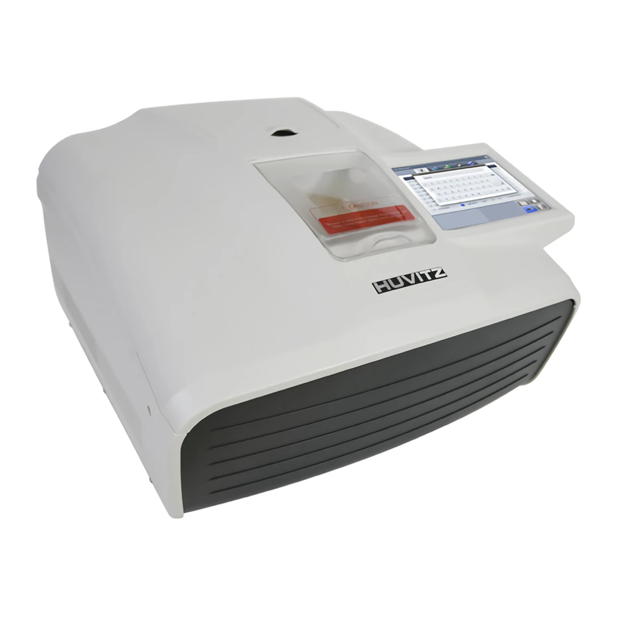
System Overview Main body (HPE-410) 3.1. Front View Frame Reader Frame Reader Cover Main Display Edging Room (Touch Screen) Edging Room Window * Built-in frame reader is not available on NTR option. Edging Room Feeler Clamp Main Wheel Wheel for Safety Bevel, Grooving... - Page 17 HPE-410 Rear View Main Switch Main Power Input and Fuse Interface Terminal • Barcode Reader • Auto Blocker Outlet for Pump 1, 2, Vacuum Cleaner • Tracer out/Driller Built-in Frame Reader Gripping Bar Gripper Stylus...
- Page 18 Devices for Edging Polycarbonate NOTE In order to process polycarbonate lens, pump 2 must be installed to supply water to the rear side of the edging room.
- Page 19 HPE-410 NOTE • Wheel types RPG Type : Bevel, Flat edging (It processes glass lens) • ① ② ③ ④ ① Glass Roughing Wheel ② Roughing Wheel ③ Finishing Wheel ④ Polishing Wheel RPW Type : Bevel, Flat edging (It cannot process glass lens) •...
-
Page 20: Blocker
Blocker 3.2. 3.2.1. HMB-8000 Front View Switch Lever Lens Adapter Setter Horizontal Scale Plate Vertical Scale Plate Lens Holder Brightness Adjustment Bottom View Power Input... -
Page 21: Cbk-4000
HPE-410 3.2.2. CBK-4000 Front View Switch Lever Lens Adapter Setter Horizontal Scale Plate Vertical Scale Plate Lens Holder Rear View / Bottom View Lamp Fixing Plate Main Switch Fuse Holder Power Input Voltage Selector... -
Page 22: Standard Accessory (Tool Box)
Standard Accessory (Tool Box) 3.3. Standard Jig for Edger Lens Adaptor Lens Adaptor Remover Feeler Tip Dressing Sticks Fuse Wrench Set Carriage-Fixing Bracket Standard Frame Jig Pattern Holde Standard Pattern LEAP-III TAPE NOTE Only LEAP-III is available for this product. Otherwise, the lens axis may move. •... -
Page 23: Installation Procedure
HPE-410 Installation Procedure Edger 4.1. ① Remove the shock-absorbing material from the packing box and take the Edger out of the box carefully. ② Open the built-in frame reader cover and remove the shock-absorbing material from the stylus workspace. ③ Loosen the screw at the Edger Front Cover and open the cover. - Page 24 NOTE • Keep the removed fixing materials in the tool box and use them again when you move the machine. Fill up more than 2/3 of the tank with water. Make sure that the water supply hose is • located upper than the pump. Check if water in the hose circulates without any interference.
-
Page 25: Blocker
HPE-410 Blocker 4.2. 4.2.1. HMB-8000 ① Remove the shock-absorbing material from the packing box and take the Manual Blocker out of the box carefully. ② Plug the AC Adapter cable into the socket at the rear side of the machine and check the LED is ON. -
Page 26: Operation
Operation Control Button 5.1. All control buttons are provided on the touch screen. 5.1.1. Tracer UI/Stop Button The Tracer UI button is used to control the built-in frame reader. When tracing start, the Tracer UI button changes to stop button. Tracer UI Button... -
Page 27: Clamp Button
HPE-410 Tracer Stop Button 5.1.2. Clamp Button To open or close the clamp, press the clamp button on the bottom of the screen. Clamp Button... -
Page 28: Edging Start/Stop Button
5.1.3. Edging Start/Stop Button To start edging, press the start button on the main screen. When the process starts, the start button changes to stop button. Edging Start Button Edging Stop Button... -
Page 29: Frame Reader
HPE-410 Frame Reader 5.2. 5.2.1. Tracer UI The Tracer UI is used to control the built-in frame reader. Frame Tracing Mode ① Job Number : You can input job number or use pre-assigned job number. ② Frame Material : Select one of the following frame materials before tracing. - Page 30 Pattern Tracing Mode ① Curve PATTERN-LO (Low Curve, 2D Tracing) PATTERN-HI (Hi Curve, 3D Tracing) With Hi Curve mode, the tilt correction will be conducted automatically. Therefore, select the Hi Curve mode for a lens with extreme curve. ②...
-
Page 31: Frame Tracing
HPE-410 5.2.2. Frame Tracing ① Place the frame between the upper grippers and the lower grippers. ② Move the frame in order that the bridge of frame is located at the central position between the left and right side grippers. -
Page 32: Blocker
Blocker 5.3. 5.3.1. Scale Plate Vertical Scale (unit:mm) Horizontal Scale (unit:mm) Near Vision guide for Bi-Focal Lens 5.3.2. Lens Adapter Setter Lens Adapter should be inserted into the Lens Adapter Setter as shown like (a). -
Page 33: Blocking Mode
HPE-410 5.3.3. Blocking Mode Active Blocking vs Passive Blocking There are two kinds of blockings, Active blocking and Passive blocking. Active blocking is a way that the Lens Adaptor is fixed at the optical center. Passive blocking is a way that the Lens Adaptor is fixed at ‘Boxing Center’... - Page 34 Comparison with active blocking and passive blocking Active Blocking Passive Blocking Blocking Optical Center of Lens Geometrical Center of Frame User Have to move the Lens Just following the Marking Spot of Lensmeter Convenience according to GUI There can be additional limitations because of PD, No additional limitation OH(Optical Height) Lens...
-
Page 35: Operation
HPE-410 5.3.4. Operation ① Put the Lens Adapter into the Lens Adapter Setter (Pay attention to the direction). ② Place the marked Lens on the Lens Holder. ③ Adjust the location of marking point according to the lens type (Bi-focal, Progressive) and Blocking Type (Optical Center, Box Center). - Page 36 Blockings according to the lens types [Single Vision] [Progressive Lens] Far Vision Eye Point Adjust the marking point of the lens to the Adjust the Far Vision Eye Point of the center of scale plate. progressive lens to the center of scale plate. [Bi-Focal Lens] [Boxing Center] Center Line of...
-
Page 37: Edger User Interface
HPE-410 Edger User Interface Main Screen 6.1. Frame Side Button Job Management Layout Option Information Function Button Edging Option Function Button 6.1.1. Side Button ① Press the R button to select right side. - Page 38 ② Press the L button to select left side. NOTE Each side of frame shape is exchanged by pressing the R button for a while. • The function of exchange R/L is useful when you selected wrong side while reading demo •...
- Page 39 Some OMA files may not be fully compatible with our system. So please note that it may • not be able to process normally. OMA import function is available after being activated in the menu. (Ask to the service • technician of HUVITZ or the technician authorized by HUVITZ.)
-
Page 40: Job Management
6.1.2. Job Management ① New : Clear current job screen and wait new job. ② Job Number : Display current job number (Press the button to change job number). ③ Job Manager : Press the job manager button to load a new job or move on to another job. NOTE •... - Page 41 HPE-410 NOTE • Following additional functions are available by pressing ‘Job Management’ button for a while. If you press ‘New’ button for a while, you can delete the current job on display • immediately. You can save current job on SD card by pressing ‘Job Number’ for a while.
- Page 42 You can start jobs with auto-blocker or remote edging host pc by pressing ‘Job Manager’ • button for a while. • The function of job request works only when communication option on configuration menu is set properly.
-
Page 43: Frame Information
HPE-410 6.1.3. Frame Information ① Frame Curve ② Circumference ③ Minimum Lens Diameter Width/Height ④ 6.1.4. Layout Option ① Binocular PD: Input prescribed binocular PD value. ② Monocular PD : Input PD values for each side (L/R). ③ Bridge Size (DBL): Input value of bridge size. - Page 44 NOTE • When you input Binocular PD value, Monocular PD values for each side are automatically calculated and vice versa. When you input Bridge Size value, FPD value is automatically calculated and vice versa. • • In case of Two Eye Tracing, the value of FPD will be automatically transmitted and displayed.
- Page 45 HPE-410 NOTE • In layout information, dialog PD, OH, Bridge Size, FPD are mandatory value. The color of input box of these values is changed when you input value. The box which is not changed from Default value is colored yellow. It changes into white •...
- Page 46 NOTE • Numeric Keypad Click the value you want to change then this numeric keypad will pop up. ① Name of the value ② Range of the value ③ Value ④ Increase/Decrease ⑤ Backspace ⑥ Reset (Cancel) – If you press it, the value goes back to original value. If you press it one more time, the numeric keypad disappears.
-
Page 47: Edging Option
HPE-410 6.1.5. Edging Option ① Edging Type Bevel Flat Groove Mini Bevel NOTE You can input additional parameters according to the selected edging type. • Grooving • ① Groove Depth ② Groove Width Mini Bevel • ① Bevel Height... - Page 48 NOTE • After you’ve selected grooving as the edging type, you can select partial grooving by pressing ‘Edging type’ button for a while. There are four ways of partial grooving. • Partial Grooving Hybrid Grooving Partial Bevel Dual (Flat+Grooving) (Bevel+Grooving) (Bevel + Flat) Grooving Relevant icon is displayed at edging type when partial grooving is selected.
- Page 49 HPE-410 ② Bevel/Groove Position Front % Front mm Rear mm Base Curve Auto Manual ③ Size Adjustment (-2.0 ~ 2.0mm) ④ Polishing Polishing Off Polishing On High Polishing ⑤ Front Safety Beveling Safety Beveling Off Safety Beveling On ⑥ Rear Safety Beveling...
- Page 50 NOTE • Polishing / Safety Beveling touch screen area ① Polishing On/Off ② Front Safety Beveling On/Off ③ Rear Safety Beveling Off/Small/Large Safety Beveling option is disabled in Hybrid Grooving (Bevel+Grooving) and Partial Bevel • (Bevel + Flat). ⑦ Lens Material Plastic Polycarbonate Hi-Index...
- Page 51 HPE-410 ⑨ Blocking Mode Optical Center Boxing(Frame) Center ⑩ Roughing Mode Normal Spiral Axial NOTE Normal mode is a mode where a lens contacts the wheel directly while processing. • Spiral mode is a mode where a lens contacts the wheel gradually with spiral rotation.
- Page 52 NOTE • Boxing Center is useful for the following cases. When PD is in eccentric position When frame is horizontally wide Super Hydrophobic Lens or Ultra Hi-Index Lens When you choose the options for Bi-Focal, Near Vision Shape will be displayed on the •...
- Page 53 HPE-410 • Using the distance (mm) mode from the front side, the operator can designate the specific moving distance. However, if the thickness of the thin part is less than twice the designated value, the machine will process at internal center, which is 50% in ratio.
-
Page 54: Detailed Edging Option
6.1.6. Detailed Edging Option ① Feeling after roughing ② Pre-Roughing ③ Feeling Position Normal Frame Change Outside of Bevel ④ Clamp Pressure Normal Strong Weak ⑤ Hydrophobic Mode... - Page 55 HPE-410 NOTE • If you use the function of feeling after roughing, you are provided with a more precise information with double-checked lens thickness after the roughing. You can change feeling mode to one-side feeling mode by pressing the feeler icon for a •...
-
Page 56: Function Button
Function Button 6.1.7. Expert Job Editor ① Menu ② Digital Designer (Digital Pattern + Hole Editor) ③ ④ Retouch Mode Clamp Button ⑤ NOTE The expert user can work more quickly by using ‘Expert Job Editor’. • • The retouch button is enabled in completed job. The hole editor is only available when the drilling machine (HDM-8000) is connected. -
Page 57: Manual Bevel/Groove Position Modification
HPE-410 Manual Bevel/Groove Position Modification 6.2. The manual position adjustment screen will be displayed after feeling process is finished when edging position mode is manual. Stop Processing Base Position Type Min/Max Thickness Region Selection Position Side View Position Modification Reset & Apply Button 6.2.1. -
Page 58: Region Selection
6.2.2. Region Selection ① Red Dot – Current Location ② Yellow Line – Manual Position ③ Move region clockwise (fine adjustment) ④ Move region counterclockwise (fine adjustment) ⑤ Move region clockwise ⑥ Move region counterclockwise ⑦ View Type ⑧ View Ratio ⑨... - Page 59 HPE-410 NOTE • Touch the lens shape area, then the red dot will be moved to the touched position. Touch Area To see the shape in actual size, touch the upper right icon. • Touch Area (Actual measurement)
- Page 60 (Auto – Shape is automatically resized fitting the screen.) Angle guideline function is turned on or off by touching the center of the shape. • Touch Area Angle guideline spacing is 10 °. •...
-
Page 61: Position Modification
HPE-410 6.2.3. Position Modification ① Front curve of the lens ② Rear curve of the lens ③ Yellow Line – Manual Position ④ Gray Line – Base Position ⑤ Bevel/Groove Preview – Distance between current position and front surface (mm) ⑥... - Page 62 NOTE • Global modification function is to move the entire edging position to the lens front surface or rear. [Move front] [Move Rear]...
- Page 63 HPE-410 NOTE • Partial modification function is to move the current edging position to the front surface or rear. [Move front] [Move Rear]...
- Page 64 NOTE • Tilting function is to fix a reference point and tilt the edging position to the lens front surface or rear. [Move front] [Move Rear]...
-
Page 65: Reset & Apply Button
HPE-410 6.2.4. Reset & Apply Button ① Reset Button – Cancel the changes ② Apply button – Apply modified position and continue to processing NOTE If you press the base position button while changing base position, previously selected • base position is initialized to selected base position. -
Page 66: Partial Grooving Screen
Partial Grooving Screen 6.3. When you select Partial Grooving mode, partial grooving screen pops up after the feeling process. Region Selection Processing Type Safety Bevel Button Reset & Apply Button... -
Page 67: Region Selection
HPE-410 6.3.1. Region Selection ① Orange Circle – Start Point ② Blue Circle – End Point ③ Red Line – Bevel / Flat edging Area ④ White Line – Grooving Area ⑤ Move start point clockwise ⑥ Move start point counterclockwise ⑦... - Page 68 NOTE • To see the shape in actual size, press the upper right icon. Touch Area (Actual measurement) (Auto – Shape resized to fit to the screen) Angle guideline pops up when you touch the center of the shape. (Guideline spacing - 10 °) •...
-
Page 69: Processing Type Selection
HPE-410 6.3.2. Processing Type Selection ① Angle of the start point ② Angle of the end point ③ Grooving (Cancel Partial Grooving) ④ Flat Edging + Grooving ⑤ Beveling + Grooving ⑥ Beveling + Flat Edging ⑦ Grooving + Grooving (Dual) ⑧... -
Page 70: Safety Bevel Button
6.3.3. Safety Bevel Button ① Front Safety Bevel OFF ② Front Safety Bevel ON ③ Rear Safety Bevel OFF ④ Rear Safety Bevel Small ⑤ Rear Safety Bevel Large. NOTE Safety bevel is not available when the processing type is Beveling + Grooving or Beveling + Flat Edging. -
Page 71: Job Manager
HPE-410 Job Manager 6.4. Job selection tab Exit Job list Function button 6.4.1. Job selection tab ① Waiting Job : Newly received Job data from built-in frame reader or external auto blocker. ② Working Job : Editing job ③ Completed Job : Finished Job ④... -
Page 72: Function Button
6.4.2. Function Button ① Open : Load the selected job ② Save : Save the selected job to SD card ③ Search : Search Job number ④ Delete : Delete selected job NOTE • Save function is only available on Waiting/Working/Completed list. If the power of the system is turned off, all job data on Waiting/Working/Completed list are •... -
Page 73: Waiting Job
HPE-410 6.4.3. Waiting Job ① Job Number: Displays the Job Number. ② Type: Displays the Edging Type with icon. ③ Reading: Displays the Tracing State with icon. ④ Frame Type: Displays the Frame Type. ⑤ FPD: Displays the FPD value. -
Page 74: Completed Job
6.4.5. Completed Job ① Edging: Displays the Edging Processing state. ② Time: Displays the job finish time. NOTE You can check current processing state with the following icons. • Waiting, Editing Complete (One side) Complete (Both sides) -
Page 75: Job Search
HPE-410 6.4.6. Job Search You can search for a job on the job list. ① Start ‘Job Search Mode’ by pressing the search button. ② Enter the job number you want with the virtual keyboard. ③ Check the list. Enter Job Number... - Page 76 You can search with only few letters, not the whole words. For example, you can search • the Job Number ‘HUVITZ_123’ only with ‘HUVITZ’ or ‘123’. • You can look at the other research results with ‘Next’ and ‘Prev’ button.
-
Page 77: Digital Pattern
HPE-410 Digital Pattern 6.5. The “Digital Pattern” ( ) modifies the lens shape in left/right, top/bottom as well as rotation and optimizes the fitting for Rimless and Semi-Rimless. Zoom Exit Touch Area R/L Preview Input Area ① Enlargement/Reduction ② Near Vision Area Enlargement/Reduction ③... -
Page 78: Enlargement/Reduction
6.5.1. Enlargement/Reduction Lens shape can be modified both horizontally and vertically. Touch Interface To modify lens shape, make use of the 8 touch points around the lens shape. Horizontal + Vertical Horizontal Vertical [Horizontal + Vertical] [Horizontal] [Vertical] Value Input You can modify the lens shape by entering the values directly in the Input Area. -
Page 79: Near Vision Area Enlargement/Reduction
HPE-410 6.5.2. Near Vision Area Enlargement/Reduction Lens shape can be changed in four directions (Bottom - Near Vision Area, Top, Left, Right). Touch Interface To modify lens shape, make use of 4 touch points around the lens shape. Left or Right... -
Page 80: Rotation
Value Input You can modify the lens shape by entering the values directly in the Input Area. ① Left ② Right ③ Near Vision Area (Bottom) ④ After selecting the item to change, enter the value using the numeric keypad. 6.5.3. - Page 81 HPE-410 [Clockwise] [Counterclockwise] Value Input You can modify the lens shape by entering value directly in the Input Area. ① Width ② Height ③ Angle (Clockwise, 0 ~ 360) Function of ① and ② are same with that of Enlargement/ Reduction mode.
-
Page 82: Partial Modification
6.5.4. Partial Modification Lens shape can be modified partially. Touch Interface Set modification area by touching any point on lens shape. The point becomes the center of the modification area. To adjust modification range, touch and drag one of 2 touch points around the selected lens shape (blue). User touch position Range adjustment point [Left]... -
Page 83: Reset
HPE-410 Lens Shape Modification You can modify the lens shape with Input button. ① Position change (counter clockwise, clockwise) ② Range change (enlargement, reduction) ③ Wide Partial Modification (concave, convex) ④ Partial Modification (concave, convex) During partial modification, where is not able to process physically is colored red. -
Page 84: Toggle R/L Sync
6.5.6. Toggle R/L Sync Function for R/L Sync. [R/L Sync On] [R/L Sync Off] NOTE “Copy” button ( ) is available when R/L sync option is turned off. Shape of the current • side is copied to the other side by pressing this button. •... - Page 85 HPE-410 NOTE • You can modify half-framed lens or rimless lens conveniently by using the digital pattern. The digital pattern is useful for the bi-focal lens or the progressive. Sometimes too small • frame shape might cut out the near vision area. In this case, the digital pattern provides the enlargement of the frame shape.
-
Page 86: Hole Editor
Hole Editor 6.6. This screen is for the edition of hole position for drilling. To use the hole editor, click the button( ) on the main screen right below, and then select the hole editor button in the upper left. Working Area Top of hole editor Preview... -
Page 87: Upper Side Of Hole Editor
HPE-410 Upper Side of Hole Editor 6.6.1. ① Hole Editor : Starts the hole editor. If the button is green, hole editor is now available. ② Digital Pattern : Starts the digital pattern. ③ Job Number : Displays the job number of currently working job. You can modify the number by touching here. - Page 88 NOTE • Elements required for drilling are displayed on working area. The figure below describes each element. Frame Horz. Coordinate Hole Center Notch or Slot Vert. Coordinate Undrillable area...
-
Page 89: Preview
HPE-410 Preview 6.6.3. ① Select Right/Left : You can change the selection of the left/right. ② Right/Left synchronization : The synchronization of the right and left side can be turned on or off. Properties or changes of the selected side are identically applied to the other side when the synchronization is on. -
Page 90: Function Buttons
Function Buttons 6.6.4. ① Select / deselect all : You can select or deselect all of the holes/slots at once. ② Retouch hole / slot : You can register the selected holes/slots for retouching. ③ Hole / Slot Easy Moving : You can move the selected holes/slots. - Page 91 HPE-410 NOTE • The button for retouching hole / slot is available after drilling is completed. The hole/slot selected to be retouched will be marked with ‘(R)’ as shown. When you press the Hole / Slot Easy Moving button, following screen will pop up. You can •...
- Page 92 : This provides the function of parallel movement. The movement of hole / slot is like below. [Hole] [Slot] : (Slot only) This provides the function to move the start position of a slot. : (Slot only) This provides the function to move the end position of a slot. : (Slot only) This provides the function to rotate a slot.
- Page 93 HPE-410 : (Slot only) This provides the function to change the length of a slot. : (Slot only) This provides the function to change a slot to a notch and to move the notch. The slot will be moved to the edge of a frame close to current position, and become a notch.
- Page 94 NOTE • On the preset, there are three functions. ① Save the hole / slot data: You can save the hole / slot data of the current job to the SD card. List of hole / slot data : This displays a list of hole / slot data in the SD card.
- Page 95 HPE-410 ③ Set preset: You can set the 8 preset buttons. ( ). You can put hole/slot saved in SD card to each button. These 8 presets can be used to add the favorite set of the hole / slot data to the current job, easily.
- Page 96 NOTE The mirroring is a function that copies the selected hole / slot to the opposite side. The distance between mirrored hole/slot and the frame edge is same with the distance between original one and the frame edge. In case of slot, the distance between the start point of a side (closest point to the frame) and the frame must be identical with the distance between the end point of the other side (closest point to the frame) and the frame (The two points must be symmetric).
-
Page 97: List Of Hole/Slot
HPE-410 List of Hole/Slot 6.6.5. It displays the hole / slot list of the current job. You can change the position of the hole / slot by pressing the coordinates displayed on the list. ① Select the hole / slot : You can select the holes / slots to make a group by pressing here. - Page 98 NOTE • Display options for X coordinate Center of frame Frame edge Display options for Y coordinate • Center of frame Bottom of box...
-
Page 99: Property Of Hole/Slot
HPE-410 Property of Hole/Slot 6.6.6. It displays the properties of the selected hole / slot. ① Group : If selected hole / slot belongs to a group, it displays the group id. If selectedn hole / slot does not belongs to a group, it displays with the ‘-’. -
Page 100: Retouch Mode
Retouch Mode 6.7. If the processed lens is too large to be to the frame, you can process the lens again with the Retouch Mode. ① Retouch Size(minus value ~ 0.0) - Input retouch size ② Activate/Cancel Polishing - You can activate polishing even if the lens has not been polished before. ③... -
Page 101: Job Editor
HPE-410 Job Editor 6.8. Job editor provides the whole edging options at once, so it is useful for the skillful users. 6.8.1. Layout Option PD (Binocular PD, R/L Monocular PD) Box Height ΔY Mix Height Bridge size (DBL) Circumference Z-tilt... -
Page 102: Edging Option
Frame Type Blocking mode Near vision area Lens type diameter 6.8.2. Edging option Edging type Lens material Bevel/Grooving position Partial grooving Polishing Safety mode Rear safety beveling Front safety beveling Roughing type Feeling after roughing Pre-roughing Feeling mode & position Clamp pressure Hydrophobic mode Drilling Quality... -
Page 103: Edging Process
HPE-410 Edging Process 6.9. 6.9.1. Edging Start Start process with following procedures after all edging option settings are completed. ① Open the edging room window. ② Release the clamp by pressing the clamp button on the screen, and then set blocked lens. -
Page 104: Edging Screen
6.9.2. Edging Screen NOTE • Some buttons are unlocked after a while. Then, you can handle another job with ‘New’ button on top of the screen. Clear the main screen with the ‘New’ button and then press the button again to load the •... - Page 105 HPE-410 (* Edging status icon is displayed for processing job) According to edging state, following icons are displayed on the main screen. • Edging Icons Processing Processed Drilling Icons Drilling assignment Drilling processing Drilling Processed (* The drilling icon is displayed only when the drilling machine (HDM-8000) is connected) During the roughing process, the lens position adjustment button is displayed at the bottom •...
-
Page 106: Edging Stop
6.9.3. Edging Stop Edging process stops by pressing the stop button on the screen at any time. Edging process stops when an unexpected situation happens. CAUTION • In case of emergency, stop the machine immediately by pressing the stop button. Motor needs some time to stop its working when you stop the machine while processing. -
Page 107: Edging Error
HPE-410 6.9.4. Edging Error In case of an unexpected situation, error message will pop up and the process will stop immediately. NOTE Please check the error message and take a proper step. And then, restart the process. -
Page 108: Edging Finish
6.9.5. Edging Finish After edging process is finished, beep sound and finish message will be provided with activated main screen. Follow these steps to take out the processed lens. ① When the wheel completely stopped, open the edging room window. ②... -
Page 109: Frame Change
HPE-410 6.10. Frame Change 6.10.1. Frame Change Lens Registration This function is for registration of the frame change lens for frame change processing. To register the frame change lens, double-click (or long click) the job number area after selecting the frame change lens on waiting tab. -
Page 110: Frame Change Mode
6.10.2. Frame Change Mode You can activate the frame change mode by touching the feeler icon on detail edging options at the right bottom of main screen. In this mode, feeler reads the lens 1mm inner than its actual size. So even when the size of the frame change lens and the edging size are similar, it helps to process without problems. -
Page 111: Frame Change Procedure
HPE-410 6.10.3. Frame Change Procedure ① Frame reader reads the lens which will be used in frame change. (when you hold the lens at pattern holder, you must block the lens adaptor at optical center of lens) ② The data will be registered to the job manager after the reading process is completed. -
Page 112: Configuration
Configuration Configuration of Edger 7.1. Press the MENU button at the bottom left of the Main screen. MENU Screen ① Preferences ② Adjustments ③ Frame reader menu ④ Control Button (Edger Stop, Clamp) ⑤ Software Version ⑥ Shutdown ⑦ Exit the menu screen... - Page 113 HPE-410 NOTE • The control button bar (Edger Stop, Clamp) is always shown at the bottom of the menu screen. You can use the control button to open or close the clamp and stop the operation of the • edger.
-
Page 114: Preferences
7.1.1. Preferences User Interface can be customized to the user’s preference. General Default settings for user interface Language – Sets default language. • Beep Sound – Turns on or off the beep sound. • Frame Fitting Mode – Applies frame fitting values R/L separately or R/L equally. •... - Page 115 HPE-410 NOTE • Setting Screen ① Tab Menu. ② Radio Button – Choose only one of a predefined sets of options. ③ List Box – Choose a list from existing options. ④ Input Box – Input value to be used by the program.
- Page 116 Layout Default settings for main screen layout option Default Side – Set default editing side. • Lens Type – Set default layout mode of main screen. • Blocking Mode – Set default blocking method. • OH Sync – Apply OH value R/L simultaneously. •...
- Page 117 HPE-410 Edging Default settings for main screen edging option Edging Start Side –Select left or right to start edging. Warning message will pop up if the • processing is not started from the selected side. Default Lens Material – Set default lens material.
- Page 118 Digital Pattern Default settings for digital pattern screen • Digital Pattern Apply Method. Fix FPD – Calculates bridge size value based on FPD. Fix Bridge Size – Calculates FPD value based on bridge size. Zoom Ratio – Set default zoom ratio of touch input area. •...
- Page 119 HPE-410 Hole Editor Default settings for hole editor screen Hole Depth – Set default hole/slot depth value. • • Hole Diameter – Set default hole/slot diameter value. Angle Default Options – Set default tilting angle mode and manual tilting value.
- Page 120 Frame Fitting Frame Fitting values are used to adjust the size variation caused by frame material difference. Master Size – Input size adjustment value for all frame material. • • Metal – Input size adjustment value for metal frame. Hard Plastic – Input size adjustment value for hard plastic frame. •...
- Page 121 HPE-410 NOTE • How to setup frame fitting values. ① Trace the metal frame with the frame reader. ② Execute edging process with Mid-index lens (low diopter lens is preferred) and carry out the fitting with the edged lens. ③ In case the edged lens is bigger than the frame, decrease the value, in case the edged lens is smaller than the frame, increase the value.
- Page 122 Comm. Port Set the communication options. • Barcode Reader (BARCODE) - Use the barcode reader. Baud Rate – Set communication speed Blocker Port (BLOCKER) – Use blocker port. • Protocol – Set communication protocol Baud Rate – Set communication speed External Driller Connection –...
-
Page 123: Adjustments
Adjustment settings are closely related to the edging quality, so keep the system default • values as much as possible. If you want to change adjustment values, ask to the service technician of HUVITZ or the • technician authorized by HUVITZ. - Page 124 General Set basic edging options. • Edging Room Window Open Warning – The processing stops if you open the window by force while processing. • PC/TRI Edging Order – The order of polishing and grooving for PC/TRI lens is set. Swap Pump1, 2 –...
- Page 125 HPE-410 Rotation You can set the number and the speed of rotation. Rotation Limit – Number of rotation is set according to the processing steps and lens materials. • • Rotation Speed – Speed of rotation is set according to the processing steps and lens materials.
- Page 126 Clamp You can set default clamping pressure value. Normal – value for Normal Pressure Mode. • • High – value for High Pressure Mode. Low – value for Low Pressure Mode. • NOTE You can input the value from 50% to 150%. 100% means 60kgf±5.
- Page 127 HPE-410 Size You can adjust the edging size. Finishing Size – Size adjustment value for finishing step. • Polishing Size – Size adjustment value for polishing step. •...
- Page 128 NOTE How to adjust finishing size. • Load internal circle pattern(Ø 50). ① ② Execute the beveled process and the rimless process for all types of lenses. ③ Check the size of processed lenses and input the adjustment value. How to adjust polishing size •...
- Page 129 HPE-410 Margin You can set margin for the following edging steps. Roughing Margin – Margin value for roughing. • Polishing Margin – Margin value for polishing. • CAUTION Margin values have influence on the lens material or edging quality. So it is recommended...
- Page 130 Axis You can adjust the distortion of axis. Main – Compensation value for main axis. • • Polishing – Compensation value for polishing axis. Grooving – Compensation value for grooving axis. • • Safety Beveling – Compensation value for safety beveling.
- Page 131 HPE-410 NOTE • How to adjust axis. ① Load internal square pattern (40mm x 40mm). ② Draw a horizontal line on the lens and locate the lens adaptor at the center and parallel to the line. ③ Execute flat edging, check the main axis, and input the adjustment value.
- Page 132 How to adjust grooving axis value. • [Add (-) value] [Add (+) value] How to adjust safety beveling axis value. • [Front] [Rear] [Front] [Add (-) value] [Add (+) value] [Add (+) value] • In main axis adjustment, use the digital pattern function to rotate square pattern 45 degrees before edging.
- Page 133 HPE-410 Bevel / Groove You can adjust bevel / groove position Bevel – Set adjustment value for bevel position. • • Groove – Set adjustment value for groove position and depth Mini Bevel – Set adjustment value for mini bevel polishing position.
- Page 134 How to adjust polished bevel position value. • [Add (-) value] NOTE • How to adjust groove. ① Load internal circle pattern (Ø 50). ② Set groove position 50% and execute grooving. ③ Check the groove position and depth. ④ The tolerance must be within ±0.1mm. •...
- Page 135 HPE-410 Safety Bevel You can adjust safety bevel position. Front – Adjust front safety bevel position. • • Rear – Adjust rear safety bevel position.
- Page 136 NOTE • How to adjust safety bevel. ① Load internal circle pattern (Ø 50). ② Turn on front and rear safety bevel options and execute bevel edging(50% position) for all types of lens materials. ③ Turn on front and rear safety bevel options and execute flat edging for all types of lens materials ④...
- Page 137 HPE-410 Wheel You can set the options related to edging wheels. Polishing Wheel Size – Set size compensation value for polishing wheel. • • Max Rimless Thickness – Set maximum width of lens for flat edging. Wheel for HI – Set Hi-index lens roughing wheel.
-
Page 138: Configuration Of Built-In Frame Reader
Configuration of Built-in Frame Reader 7.2. How to start the configuration ① Press the ‘Menu’ button on the main screen. ② Press the ‘Tracer’ button on the menu screen and then select the ‘Setting’ tab. Setting Screen Default Frame Material – Set default frame material value of the Tracer UI. •... -
Page 139: System Maintenance
HPE-410 System Maintenance Automatic Calibration of Built-in Frame Reader 8.1. Automatic Calibration of Frame Reader is required with the following cases, • When the Size or Axis value of the traced data seems to have a problem, • When the Frame Reader seems to have a problem in operating normally. -
Page 140: Stroke Calibration
Stroke Calibration 8.1.1. Procedures for stroke calibration. ① Press the ‘Menu’ button on the main screen. ② Press the ‘Tracer’ button on the menu screen. ③ Select ‘Maintenance(Calibration)’ tab on the screen. ④ Pull the Gripping bars to the maximum. ⑤... -
Page 141: Built-In Frame Reader Test Mode
HPE-410 Built-in Frame Reader Test Mode 8.2. Test Mode is efficient to find out whether the built-in frame reader works properly or not. ① All sensor information ② Initialize tracer ③ Exit Test Mode ④ Gripper / Theta / X / R / Z axis test ... -
Page 142: Automatic Calibration Of Edger
If the “Check the hall sensor contact” message is displayed while using the edger, you • can calibrate the sensor value with the ‘Hall Sensor Contact Calibration’ function. CAUTION Calibration function has influence on the edging quality so ask advice of the service technician of HUVITZ or the technician authorized by HUVITZ if necessary. -
Page 143: Test Mode
HPE-410 Test Mode 8.4. Test Mode is efficient to find out whether the machine works properly or not. Sensor 8.4.1. It displays all sensor values of the edger. ① All sensor information ② Refresh sensor status ③ Initialize edger ④ Exit Test Mode... - Page 144 NOTE • Sensor List X – X axis PI sensor value Y – Y axis PI sensor value R – R axis PI sensor value Contact – Main contact sensor value Feeler – Feeler encoder value & switch state ...
-
Page 145: Y / R
HPE-410 X / Y / R 8.4.2. You can check X / Y / R axis. ① X axis test ② Y axis test ③ R axis test ④ X / Y / R sensor state... -
Page 146: Feeler
Feeler 8.4.3. You can check the Feeler. ① Initialize feeler / Feeler test ② Feeler sensor and switch state... -
Page 147: Sbg / Wheel
HPE-410 SBG / Wheel 8.4.4. You can check SBG ass’y and wheel. ① SBG ass’y test ② SBG motor test ③ Wheel test ④ SBG and wheel sensor status... -
Page 148: Pump
Pump 8.4.5. You can check pump and vacuum. ① Stop all pumps ② Pump 1 test ③ Pump 2 test ④ Vacuum test ⑤ Pump & Vacuum state... -
Page 149: Clamp
HPE-410 Clamp 8.4.6. You can check clamp. ① Clamp test ② Clamp sensor state... -
Page 150: Pi / Motor
8.4.7. You can check all the PI sensors and motors. If the test fails, ask advice of the service technician of HUVITZ or the technician authorized by HUVITZ. ① X PI – X axis PI sensor test ② Y PI – Y axis PI sensor test ③... -
Page 151: Wheel Dressing
HPE-410 Wheel Dressing 8.5. Wheel dressing is useful to maintain the wheel performance because it removes the lens debris in the wheel. • Main Wheel – Glass Roughing, finishing and polishing wheel manual dressing mode Safety Bevel – Safety beveling wheel manual dressing mode •... -
Page 152: Statistics
Statistics 8.6. It shows statistic information of the processed lens. Current Statistics 8.6.1. It shows the number of lenses that have been processed since the reset point. NOTE • The edging is counted only after the edging completes successfully. Detailed information varies depending on the type of wheel. •... -
Page 153: Wheel Statistics
HPE-410 Wheel Statistics 8.6.2. It shows wheel usage NOTE Wheel statistics value is counted immediately after the lens has been processed on the • appropriate wheel. You can reset wheel statistics values whenever you need. • The wheel statistics values are for reference to determine replacement time, so it is not •... -
Page 154: Total Statistics
Total Statistics 8.6.3. It shows the total number of lenses that have been processed since the very first time of the installation. NOTE The edging is counted only after the edging completes successfully. • • Total statistics values cannot be initialized. -
Page 155: Date & Time
HPE-410 Date & Time 8.7. You can change the system time. Please set the date and time first after you install this machine. Touch Test 8.8. You can check the normal operation of the touch screen... -
Page 156: Configuration Management
Configuration Management 8.9. You can backup or restore system configuration data. Backup – Backup configuration data to SD card. ① Restore – Restore configuration data from SD card ② Factory Reset – Reset to factory default setting ③ NOTE You can backup the configuration data as many times as you need, because you can •... -
Page 157: Sw Upgrade
8.10. SW Upgrade You can upgrade software. HPE-410 consists of three kinds of software. GUI software handles user input and MOTOR software controls mechanical parts of the edger and TRACER software controls built-in frame reader. ① GUI – Upgrade GUI software ②... -
Page 158: Maintenance Code
How to upgrade MOTOR or TRACER software • ① Copy upgrade file to a SD card and insert the SD card into the system. ② Check the SW version displayed on the upgrade dialog box. ③ Press the MOTOR or TRACER button to start upgrade. ④... -
Page 159: Maintenance Tips
8.12.2. Regular Maintenance It is recommended to keep the regular maintenance cycle in order to maintain the Edging Performance. Be sure to carry out the regular maintenance by the service technician of HUVITZ or the technician authorized by HUVITZ. Regular Maintenance Cycle : 1,500 ~ 2,000 pieces of Lens edged 8.12.3. -
Page 160: Blocker(Cbk-4000) Lamp Replacement
Blocker(CBK-4000) Fuse Replacement WARNING Be sure to use the appropriate Fuse. Otherwise it may damage the product or cause fire 8.12.4. Blocker(CBK-4000) Lamp Replacement In case of blocker lamp replacement, be sure to use the lamp described below. Lamp : 6V 8W (Optic Lamp) ... -
Page 161: Cleaning
HPE-410 8.12.5. Cleaning ① Sweep the outer surface and LCD panel with soft fabric material. ② When you do not use this device, wrap it with dust cover. CAUTION Before cleaning your product, disconnect the power cord. • • Since the exterior of the product is easily scratched, be sure to use soft cleaning cloth. -
Page 162: Troubleshooting Guide
Troubleshooting Guide If problems occur, Please review the following list and take remedial action as needed. If you cannot solve the problem after checking the entire list, please contact HUVITZ Problem Cause Solution Tracing size Tip abrasion, gap occurrence. Frame/pattern calibration. - Page 163 HPE-410 Cannot select the Enter the R/L frame curve values at job Do not have the information of frame curve. auto bevel position editor. If the lens has big diameter and high curve, it Bevel/groove Apply the pre-roughing mode if occurred can be interference with instruments.
-
Page 164: Specifications And Accessories
Specifications and Accessories 10.1. Standard Accessories User’s Manual ··················································································································· 1 Lens Adapter ··················································································································· 20 LEAP-III Tape ······································································································· 100 pieces Lens Adapter Remover ········································································································ 1 Standard Frame (for Frame Reader Calibration) ······································································· 1 Standard Pattern (for Frame Reader Calibration) ······································································ 1 Pattern Holder ···················································································································... -
Page 165: Specifications
HPE-410 10.2. Specifications 10.2.1. Specifications of Edger Beveling – Normal, Mini, Partial, Auto, Manual Mode Flat Edging Edging Mode Grooving – Normal, Partial, Hybrid, Dual, Auto, Manual Mode Safety Beveling Polishing Lens Material Plastic, Glass, High Index, Polycarbonate, Trivex® Max : 90mm Edging Size Min : Rimless 18.5mm (without safety bevel) -
Page 166: Drawings Of System
10.3. Drawings of System 10.3.1. Drawings of Edger... -
Page 167: Drawings Of Blocker (Hmb-8000)
HPE-410 10.3.2. Drawings of Blocker (HMB-8000) 10.3.3. Drawings of Blocker (CBK-4000) -
Page 168: Service Information
If you can’t contact with your local distributor, you can directly get in touch with the service • department of the HUVITZ using the phone number and the address written in the below table. How to Contact HUVITZ Co., Ltd HUVITZ Co., Ltd.
Need help?
Do you have a question about the HPE-410 and is the answer not in the manual?
Questions and answers