
Related Manuals for Siemens Cerberus PRO FC721


Summary of Contents for Siemens Cerberus PRO FC721
- Page 1 FC721 Fire control panel Technical Manual Building Technologies A6V10211100_f_en_-- 2015-12-15 Control Products and Systems...
- Page 2 Issued by: Siemens Switzerland Ltd. Building Technologies Division International Headquarters Gubelstrasse 22 CH-6301 Zug Tel. +41 41 724-2424 www.siemens.com/buildingtechnologies Edition: 2015-12-15 Document ID: A6V10211100_f_en_-- © Siemens Switzerland Ltd, 2009 2 | 118 Building Technologies A6V10211100_f_en_-- Fire Safety 2015-12-15...
-
Page 3: Table Of Contents
Table of contents About this document ................7 Applicable documents ................. 9 Download center ..................9 Technical terms and abbreviations .............. 9 Revision history ..................10 How displays are represented in the document ..........11 Safety ....................12 Safety instructions ..................12 Safety regulations for the method of operation ...........14 Standards and directives complied with............16 Release Notes ...................16 Cyber security disclaimer ................16... - Page 4 C-NET detector line ................... 57 6.5.1 Connectable C-NET devices ............58 6.5.2 C-NET topology and connection ..........62 6.5.3 Wiring principle behind C-NET devices ........64 Structure and function................66 Indication and operating elements.............. 66 Extra indication and operating devices ............68 7.2.1 Mimic display driver FT2001 ............
- Page 5 10.8 Detailed commissioning steps ..............95 10.8.1 Preparing 'Station' for commissioning ..........95 10.8.2 Preparing 'Station' for commissioning –without BDV installation ...96 10.8.3 Auto-configuring 'Station'.............96 10.8.4 Auto-configuring the detector line ..........97 10.8.5 Loading automatically created configuration to the PC....98 10.8.6 Adapting configuration ..............98 10.8.7 Switch off ..................99 10.8.8...
- Page 6 6 | 118 Building Technologies A6V10211100_f_en_-- Fire Safety 2015-12-15...
-
Page 7: About This Document
About this document Applicable documents 1 About this document Goal and purpose The information provided in this technical manual is a summary of the key procedures and functions required to assemble, install, commission, and service the FC721 fire control panel system. The aim of this technical manual is to provide experienced and qualified personnel with a quick guide to the necessary processes. - Page 8 About this document Applicable documents Document identification The document ID is structured as follows: ID code Examples ID_ModificationIndex_Language_COUNTRY A6V10215123_a_de_DE -- = multilingual or international A6V10215123_a_en_-- A6V10315123_a_--_-- Date format The date format in the document corresponds to the recommendation of international standard ISO 8601 (format YYYY-MM-DD). Conventions for text marking Markups Special markups are shown in this document as follows:...
-
Page 9: Applicable Documents
1.2 Download center You can download various types of documents, such as data sheets, installation instructions, and license texts via the following Internet address: http://siemens.com/bt/download Enter the document ID in the 'Find by keyword' input box. κ You will also find information about search variants and links to mobile applications (apps) for various systems on the home page. -
Page 10: Revision History
About this document Revision history 1.4 Revision history The reference document's modification index applies to all languages into which the reference document is translated. The first edition of a language version or a country variant may, for example, have the modification index 'd' instead of 'a' if the reference document already has this modification index. -
Page 11: How Displays Are Represented In The Document
About this document How displays are represented in the document Version Edition date Brief description 2010-07 Edition for MP3.0 XS ● Amendments to MP3.0 ● Amendments to PMI & mainboard FCM2027 ● Various minor changes ● Naming amended 2009-05 Technical manual FC721 1.5 How displays are represented in the document With very few exceptions, the fire control panels and fire terminals are displayed in this document in tables. -
Page 12: Safety
Safety Safety instructions 2 Safety 2.1 Safety instructions The safety notices must be observed in order to protect people and property. The safety notices in this document contain the following elements: ● Symbol for danger ● Signal word ● Nature and origin of the danger ●... - Page 13 Safety Safety instructions How risk of injury is presented Information about the risk of injury is shown as follows: WARNING Nature and origin of the danger Consequences if the danger occurs ● Measures / prohibitions for danger avoidance How possible damage to property is presented Information about possible damage to property is shown as follows: NOTICE Nature and origin of the danger...
-
Page 14: Safety Regulations For The Method Of Operation
2.2 Safety regulations for the method of operation National standards, regulations and legislation Siemens products are developed and produced in compliance with the relevant European and international safety standards. Should additional national or local safety standards or legislation concerning the planning, mounting, installation,... - Page 15 Disregard of the safety regulations Before they are delivered, Siemens products are tested to ensure they function correctly when used properly. Siemens disclaims all liability for damage or injuries caused by the incorrect application of the instructions or the disregard of danger warnings contained in the documentation.
-
Page 16: Standards And Directives Complied With
Safety Standards and directives complied with 2.3 Standards and directives complied with A list of the standards and directives complied with is available from your Siemens contact. 2.4 Release Notes Limitations to the configuration or use of devices in a fire detection installation with a particular firmware version are possible. -
Page 17: System Overview
System overview Cyber security disclaimer 3 System overview Cerberus PRO fire control panels FC721 are operated as standalone control panels. FC721 fire control panels cannot be networked with one another or with other FS720 fire control panels. Cerberus PRO fire control panels FC721 support operation of the CNET detector line as a loop or stub. -
Page 18: Station Types
System overview Station types 3.1 Station types Overview of the fire control panel FC721 and options FC721 in housing (Eco) FC721-ZZ FC721-YZ FC721-HZ Standard operating unit Operating unit with integrated LED Operating unit with integrated indicator (24 indicator groups, each EVAC-NL operating unit according with a red/green and yellow LED) to the requirements for the... -
Page 19: Planning
Planning FC721 system limits and options 4 Planning 4.1 FC721 system limits and options FC721 System limits Detector line Max. C-NET addresses 126 *(1 loop or 2 stubs) Number of loops or stubs 1 loop or 2 stubs Number of devices per loop Max. -
Page 20: Functions
Planning Functions 4.2 Functions This chapter describes the most important functions that can be supported by the fire detection system. Decision on alarm The danger signals of the detectors are evaluated by the zone. The decision on alarm is made at zone level. Decision on alarm can be configured as follows for each zone: ●... -
Page 21: Defining Controls
Planning Functions 4.2.1 Defining controls Connections for controls are available on the following components / control panels: ● Fire control panels FC721 ● Input module FDCI221 ● Input module FDCI222 ● Input/output module FDCIO222 ● Input/output module FDCIO222 ● Input/output module FDCIO223 ●... -
Page 22: Mounting
Mounting Mounting and assembling a station 5 Mounting 5.1 Mounting and assembling a station Before mounting and installation, check all the fire detection installation components visually for damage caused by improper transport. Cerberus Figure 3: Unpacking and checking ● Components with clear signs of damage must not be used in the station or operated as fire detection installation components. -
Page 23: Mounting Instructions
Mounting Mounting instructions 5.2 Mounting instructions The station's product insert contains an mounting model to assist with mounting. The dimensions needed and details of the mounting points are shown on the mounting model. Details on mounting and installation can be found in the reference documents. -
Page 24: Surface-Mounted Assembly
Mounting Mounting instructions 5.2.1 Surface-mounted assembly ● Any surface irregularities can be compensated with washers or wooden wedges. ● The rear panel is attached to the wall using screws with a diameter of 6 mm. ● The supplied edge protection strip must be placed around rectangular breakout openings. - Page 25 Mounting Mounting instructions Cerberus Figure 4: Mounting of the FC721 Recommended display height approx. 1.6 to 1.7 m Width of the FC721: 430 mm Distance from door of at least one door leaf width Height of the FC721: ● 398 mm ●...
- Page 26 Mounting Mounting instructions Assembling the FC721 and additional housing (option) The FC721 is supplied inside the Eco housing. An additional empty housing (Standard) can be assembled and connected for a larger battery capacity. This has space for an additional 150 W power supply and larger batteries.
- Page 27 Mounting Mounting instructions Mounting steps 1. Break out the required openings for feeding the cables at the bottom of the FC721 and the mounting holes for assembling the housing. 2. Break out the required openings for feeding cables and the mounting holes for housing assembly at the top on the rear panel of the extra housing.
-
Page 28: Mounting And Wiring The Operating Unit
Mounting Mounting instructions 5.2.2 Mounting and wiring the operating unit From IP5, the PMI & mainboard FCM2027 is used. You will find detailed information in document A6V10210368. Figure 6: View of an FC721 with open operating unit Connection (X3) for the ribbon cable on the periphery board Hinge Cable routing to the optional components Cable ties for fixing the cables... - Page 29 Mounting Mounting instructions Figure 7: Detail view of the hinge of the operating unit Cut-out section on the rear panel for the hinge of the operating unit Hinge of the operating unit Screw for securing the hinge Mounting steps 1. From the rear side, hang the operating unit by inserting the hinges (2) into the openings in the rear panel of the housing (1).
- Page 30 Mounting Mounting instructions Figure 8: Inserting the inscription strips into the operating unit Inscription LEDs Inscription standard keys 2 Inscription standard keys 1 Inscription station type 30 | 118 Building Technologies A6V10211100_f_en_-- Fire Safety 2015-12-15...
-
Page 31: Led Module
Mounting LED module 5.3 LED module The LED module installed in the FC721-YZ contains 24 groups, each with one red/green and one yellow LED. Any events can be assigned to the LEDs. Each LED may be configured as a static or flashing indicator. Normally the LED indicator is used as a zone indicator. -
Page 32: Evac-Nl Operating Unit Fto2007-N1 [Nl] (Fc721-Hz Only)
Mounting EVAC-NL operating unit FTO2007-N1 [NL] (FC721-HZ only) 5.4 EVAC-NL operating unit FTO2007-N1 [NL] (FC721- HZ only) The EVAC-NL operating unit [NL] is an evacuation control unit for the functions required in the Netherlands. It enables the operation of a maximum number of 10 evacuation zones. -
Page 33: Options
Mounting Options 5.5 Options 5.5.1 Fitting extra relay Figure 9: Mounting of two relays Fixing screws for the DIN rail Relays 1 + 2 DIN rail End clamp for the relays Mounting steps 1. Insert the relays (3) on the DIN rail (2) and press them down until they latch. 2. -
Page 34: Installing An Rs232/Rs485 Module
Mounting Options 5.5.2 Installing an RS232/RS485 module This component is installed in exactly the same way as for the operating units with the PMI & mainboard FCM2004 and the PMI & mainboard FCM2027. No more than one single interface module (RS232 or RS485) can be installed in an FC721. - Page 35 Mounting Options Figure 11: Installation of the serial modules RS232 module in slot X14 RS485 module in slot X19 2x fixing screw X14 Slot for RS232 module on the operating unit Mounting links on support plate X19 Slot for RS485 module on the operating unit Nut for screwed cable gland Connection terminal on RS232 module Screwed cable gland...
- Page 36 Mounting Options Mounting steps 1. Mount the cable gland (5) with the nut (4) on the flange between the fastening tabs (3). 2. Plug the serial module (1 or 6) into the corresponding connector (X14 or X19). 3. Secure the serial module to the fastening tabs (4) using the two screws (2). 4.
- Page 37 Mounting Options 5.5.2.2 X2 on RS485 module Designation Description RS485_A Line A RS485_B Line B Not connected Not connected Admissible cable cross-section: 0.2…1.5 mm² RS485_A RS485_B T1 First participant Tn Last participant *) Stub lines must not exceed 20 m! ●...
-
Page 38: Install Shield Connection Terminal Blocks
Mounting Options 5.5.3 Install shield connection terminal blocks Figure 12: Mounting of the shield connection terminal blocks Shield connection terminal block Philips screws M 3/6 Camp bar Mounting steps 1. Secure the clamp bar (2) above the rectangular cable breakout opening on the right with two screws (3) 2. -
Page 39: Cable Kit (Communication)
Mounting Options 5.5.4 Cable kit (communication) The cable kit (communication) FCA2014-A1 is used as an intermediate piece for wiring the external lines to the modules on the operating unit. The connecting cables supplied are fully assembled and have a length of 1110 mm. The cable kit is mounted in the top right of the housing instead of the shield connection terminal blocks. -
Page 40: Insert License Key
Mounting Options 5.5.5 Insert license key The license key (S1) FCA2033-A1 is inserted in the corresponding holder on the rear of the operating unit. Figure 14: Using the license key on the operating unit with PMI & mainboard FCM2027 Figure 15: Using the license key on the operating unit with PMI & mainboard FCM2004 Holder for the license key License keys Inserting... -
Page 41: 19" Mounting Kit
Mounting Options 5.5.6 19" mounting kit The 19" mounting kit FHA2016-A1 serves as a retainer for installing a station into a 19" rack or into a 19" cabinet. To fix a station, the two retainers enclosed with the kit must be mounted. The mounting instructions described below apply to all housing types. -
Page 42: Installation
Installation Options 6 Installation The following installation instructions refer to the specifications of the EN 54 standard and the manufacturer's recommendations. The installation may only be undertaken by an electrician. Detailed instructions can be found in the system documentation. ● Use a suitable cable, e.g., NYM 3 x 1.5 mm (max. -
Page 43: Protection Elements
Installation Protection elements 6.1 Protection elements Electro-magnetic influence and over-voltages may lead to faults in the fire detection installation. Protection elements minimize these faults. All stations are equipped with fine protection and EMC filters in the factory. This applies to the components listed below: ●... -
Page 44: Operation With Battery Backup
Installation Supply concept 6.2.1 Operation with battery backup The ↑ stations are normally operated with a power supply unit and batteries. The power supply unit feeds the hardware with galvanically isolated system voltage, simultaneously charging the batteries. Together with the batteries, the power supply unit assumes the function of an uninterruptible power supply unit. -
Page 45: Position Of Printed Circuit Boards / Components
Installation Position of printed circuit boards / components 6.3 Position of printed circuit boards / components Position of components in the FC721 Batteries Power supply 70 W Mains connection terminals (L1,N,PE) Periphery board (1-loop) Type plate (enclosed, must be attached to the outside of the control panel housing at a clearly visible point) Options (extract) -
Page 46: Power Supply - Mains Voltage Connection
Installation Power supply - mains voltage connection 6.4 Power supply - mains voltage connection When supplied from the factory, the power supply's internal cabling is already connected. Power supplies available ● Standard: DC 24 V / 2.5 A, power 70 W, max. battery capacity which can be connected 17 Ah (in the FC721, no more than 7 Ah due to a lack of space) ●... - Page 47 Installation Power supply - mains voltage connection Connecting mains voltage WARNING High voltage! Danger to life! Risk of electric shock ● Before connecting the mains voltage ensure that it is not energized and is locked to prevent it being activated. 1.
- Page 48 Installation Power supply - mains voltage connection Additional empty housing If a power supply (150 W) is needed, this must be accommodated in an additional empty housing (Standard) together with the batteries. Figure 20: Housing (Standard) for additional batteries 48 | 118 Building Technologies A6V10211100_f_en_-- Fire Safety...
-
Page 49: Emergency Power Supply
Installation Power supply - mains voltage connection 6.4.1 Emergency power supply Should the AC mains voltage fail, the emergency power supply will be provided by the connected batteries with no interruptions. The emergency power bridging time depends on the control panel's quiescent and alarm current and the battery capacity used. -
Page 50: Batteries
Installation Power supply - mains voltage connection 6.4.2 Batteries Calculating the battery capacity Determine the battery capacity with the following formula: = (I ) * k Batt R total A total Battery capacity in [Ah] Batt Sum of operating current of all consumers in quiescent condition [A] R total Sum of operating current of all consumers in alarm condition [A] A total... - Page 51 Installation Power supply - mains voltage connection Determining the battery type Determine the battery type on the basis of the calculated battery capacity (see table). Designation Type Capacitance Order number Battery (12 V, 7 Ah, VDS) FA2003-A1 7 Ah A5Q00019353 Battery (12 V, 12 Ah, VDS) FA2004-A1 12 Ah...
-
Page 52: Periphery Board
Installation Power supply - mains voltage connection 6.4.3 Periphery board Position of connection terminals on periphery board (1-loop) of FC721 fire control panel. F601 F501 F400 F401 X400 Figure 22: View of periphery board (1-loop) Connection of power unit Ribbon cable plug connection to PMI & mainboard (operating unit on pivot frame) Monitored outputs for acoustic signal transmitter, alarm and fault messages... -
Page 53: Alarm Relay
Installation Power supply - mains voltage connection 6.4.3.1 Relay for fault and alarm (RT activation) Allocation of connection terminals on periphery board (1-loop) of FC721. A cable cross-section of 0.2 to 1.5 mm can be connected to the terminals. Designation Description FAU_NC Break contact fault (normally closed) - Page 54 Installation Power supply - mains voltage connection 6.4.3.2 Monitored outputs for alarm and fault (FT activation) Connection terminals on the periphery board (1-loop) of FC721. A cable cross- section of 0.2 to 1.5 mm can be connected to the terminals. Designation Description FAU_OUT...
- Page 55 Installation Power supply - mains voltage connection 6.4.3.3 Connection of monitored acoustic signal transmitters Connection terminals on the periphery board (1-loop) of FC721. A cable cross- section of 0.2 to 1.5 mm can be connected to the terminals. Designation Description FAU_OUT Output fault VSYS_O...
- Page 56 Installation Power supply - mains voltage connection 6.4.3.4 Configurable inputs/outputs Connection terminals on periphery board of FC721 station. A cable cross-section of 0.2 to 1.5 mm can be connected to the terminals. Designation Description GND_01 (–) supply output 1 DC 20 V – DC 30 V/1 A VSYS_01 (+) supply output 1 I/O4...
-
Page 57: C-Net Detector Line
Installation C-NET detector line 6.5 C-NET detector line Up to 126 devices, such as automatic fire detectors, manual call points, transponders, and other C-NET components, can be connected to the C-NET detector line. The connection of the C-NET detector line is on the periphery board. Most line devices, such as fire detectors, are supplied with the operating voltage required directly by the C-NET. -
Page 58: Connectable C-Net Devices
Installation C-NET detector line 6.5.1 Connectable C-NET devices The table below contains a list of all devices which can be connected to the C-NET detector line. It also highlights which devices feature an alarm indicator (AI) and to which an external alarm indicator (Ext. AI) or a sounder base (DBS720) can be connected. - Page 59 Installation C-NET detector line Device type Type Description ↑ AI Ext. AI DBS 720 Manual call point FDM221 Direct activation for indoor applications – – Indirect activation (large housing) – FDM223 FDM223H FDM223-Ex Indirect activation (large housing) for – areas at risk of explosion FDM224 Indirect activation (large housing) –...
- Page 60 Installation C-NET detector line Device type Type Description ↑ AI Ext. AI DBS 720 Line separator FDCL221 – – Line separator for the correct connection of several stub lines at one point on a loop FDCL221-M Multi line separator module for the –...
- Page 61 Installation C-NET detector line Device type Type Description ↑ AI Ext. AI DBS 720 FDOOT271 – Neural radio fire Optical-thermal fire detector with radio detector (SWING) transmission to the radio gateway FDCW241 Radio manual call FDM273 Indirect activation via radio gateway –...
-
Page 62: C-Net Topology And Connection
Installation C-NET detector line 6.5.2 C-NET topology and connection Permissible topology for the C-NET The C-NET can be wired in the topology shown below. Regardless of the topology (loop, stub or loop with sub-stub), the C-NET system limits, such as length, cable resistor, number of users etc., must be observed. - Page 63 Installation C-NET detector line The connection terminals for the C-NET are on the periphery board. Figure 24: Position of C-NET connection terminal on the periphery board ● Max. 126 C-NET devices are permitted on the C-NET connection (block of 4 terminals).
-
Page 64: Wiring Principle Behind C-Net Devices
Installation C-NET detector line Cable types As a result of national standards and requirements, installation may require a particular cable type. Note the respective requirements and planning documents. The following cable types can always be used for cabling the detector line: ●... - Page 65 Installation C-NET detector line Cerberus Figure 27: Wiring example of C-NET detector devices on stub (1) If shielded connection cables are used, the cable shielding must be connected on one side. * The number of connectable C-NET devices and the max. line length depend on the device connection factor.
-
Page 66: Structure And Function
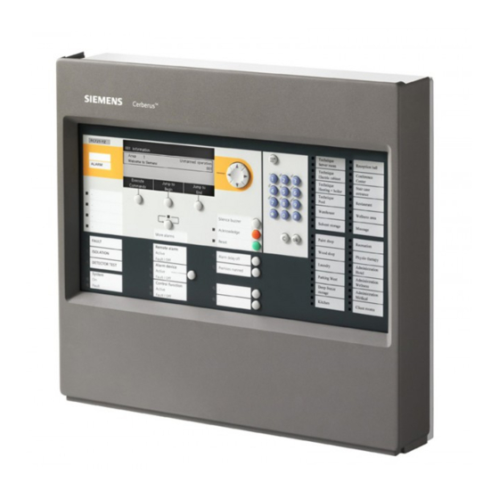
Structure and function Indication and operating elements 7 Structure and function 7.1 Indication and operating elements Fire control LED module Floor repeater Floor repeater Cerberus panel FC721 FTO2008 terminal display Remote FT2010 FT2011 Indication Alarm Pre-alarm Fault Isolation Test mode Technology Activation Information (Note) - Page 67 Structure and function Indication and operating elements The FC721 has an integrated operation and indicator field which can be used to operate, maintain and (with limitations) configure the station. Cerberus Figure 28: Operation and indicator field front of Cerberus fire control panel Display, illuminated with plain text display Cursor keypad for navigation/selection of menu items Menu button...
-
Page 68: Extra Indication And Operating Devices
Structure and function Extra indication and operating devices 7.2 Extra indication and operating devices The FT2010 floor repeater terminal and FT2011 floor repeater display allow for the decentralized indication of the most important events in the fire detection system and limited operation. Both devices can be connected to the C-NET directly as bus users. -
Page 69: Mimic Display Driver Ft2001
Structure and function Connecting external alarm indicators 7.2.1 Mimic display driver FT2001 The mimic display driver is a parallel LED indication for the system-wide signaling of events and is connected to the C-NET detector line. The LED are built in a ground plan panel. 7.3 Connecting external alarm indicators Some C-NET devices have an output where normally an ↑... -
Page 70: Software
Structure and function Software 7.4 Software The following software is available for planning, configuration and commissioning: For programming the object- and customer-specific control panel functions. FXS7212 Cerberus Engineering Tool FX7220 Cerberus Remote Indicates a graphic representation of a station's PMI, provided that the PC is connected to the station. -
Page 71: Operation Functions
Operation functions Selection and opening / execution 8 Operation functions The following chapters contain descriptions of important functions for directly operating the ↑ site. You will find information on the system functions in the corresponding chapter. 8.1 Selection and opening / execution After calling up the main menu and any other list, the first entry in the list is selected. -
Page 72: Indication Of The Position And Length Of The List
Operation functions Indication of the position and length of the list 8.3 Indication of the position and length of the list There is a vertical bar along the side of a list when the list is longer than can be indicated on the display. -
Page 73: Entry Of Numbers And Letters
Operation functions Entry of numbers and letters 8.6 Entry of numbers and letters You can use the keyboard to enter numbers and letters in input dialogs. Numeric entry ● The number of underscores corresponds to the number of possible positions for the entry. -
Page 74: Connectivity And Communication With 'Station
Connectivity and communication with 'Station' Setting Windows firewall 9 Connectivity and communication with 'Station' A PC does not have to be directly connected to a ↑ 'Station' to be able to communicate with a 'Station' in the ↑ 'Site'. The PC can be connected to any place in the Ethernet. -
Page 75: Windows 7 / Windows 8 / Windows 10
Setting Windows firewall 9.1.2 Windows 7 / Windows 8 / Windows 10 There are different ways of setting up firewall rules in Windows 7/8/10. The following settings apply for Siemens PCs which use group guidelines controlled by the domain. NOTICE The following settings must be made under Local Security Policy. -
Page 76: Connecting The Pc To The Station
Connectivity and communication with 'Station' Connecting the PC to the station 5. Set the following values: – 'Protocol type': 'UDP' – 'Local port': 'Specific Ports', and enter the value range '50067-50070' in the box. – 'Remote port': 'All Ports' 6. Confirm with 'OK'. ... -
Page 77: Disconnecting The Pc From The Station
Connectivity and communication with 'Station' Disconnecting the PC from the station 9.3 Disconnecting the PC from the station As the IP address is bound to the MAC address while there is a connection between the PC and the ↑ 'Station' and as it remains in the cache even in the case of a short break in the connection of ≤2 min., you must observe the following instructions. -
Page 78: Initializing 'Station
Connectivity and communication with 'Station' Initializing 'Station' 9.5 Initializing 'Station' ● Each ↑ 'Station' in a system with several networked 'Stations' must have a unique address. ● Once a 'Station' has been started for the first time or once the firmware on the main CPU has been updated, a 'Station' has the address '1'. - Page 79 Connectivity and communication with 'Station' Initializing 'Station' Initialize 'Station' NOTICE Connection module (card cage) FCA2006-A1 defective or installed incorrectly Control panels identified incorrectly, e.g. FC726 identified as FC724. ● Check that the connection module (card cage) FCA2006-A1 is installed correctly. NOTICE Faulty initialization for networked station During initialization, the station must not be connected to the network or any other...
-
Page 80: Loading Configuration From The Pc To The Station
Connectivity and communication with 'Station' Loading configuration from the PC to the station 9.6 Loading configuration from the PC to the station You can use the 'Download site' function to load the configuration of one ↑ 'Site' from the Cerberus-Engineering-Tool on the PC into the 'Station'. NOTICE Different network configuration in Cerberus-Engineering-Tool and networked ↑... - Page 81 Connectivity and communication with 'Station' Loading configuration from the PC to the station ϖ The ↑ 'Site' is opened in Cerberus-Engineering-Tool. ϖ The PC is connected to the 'Station'. ϖ Networked 'Stations' are initialized. ϖ 'Station' and Cerberus-Engineering-Tool have the same 'Site' ID. ϖ...
-
Page 82: Loading Configuration From The Station To The Pc
Connectivity and communication with 'Station' Loading configuration from the station to the PC 9.7 Loading configuration from the station to the PC The 'Upload site' function can be used to load the configuration of a ↑ 'Site' to Cerberus-Engineering-Tool on the PC. ϖ... - Page 83 The progress is displayed in the 'Create backup embedded configuration' window. Backup file ● The backup file is saved in the following directory as standard: C:\ProgramData\Siemens\FX7230\[Softwareversion]\Sites\embeddedBackups ● The backup file has the following name: <'Site' name>_<backup counter>(_incomplete).fsc Example: Test_Site_007_incomplete.fsc –...
-
Page 84: Commissioning
Commissioning Creating a backup of the 'Site' configuration 10 Commissioning This chapter describes initial commissioning of the Cerberus PRO fire control panel (individual control panel, not networked). ● Activating access level ● Start auto-configuration ● Display C-NET line devices ● Enter customer texts for the control panel, C-NET and individual line devices via the control panel keypad Figure 31: Line tester FDUL221... -
Page 85: Activating Access Level
Commissioning Activating access level 10.1 Activating access level The 'Station' is protected against unauthorized operation by access levels. Authorization for access level 3 is needed for the functions described below. If the authorization code is not entered, operation is only possible in access level 1 (guest), e.g., for acknowledging the control panel buzzer or scrolling through the display messages. -
Page 86: Auto-Configuration Of Control Panels
Commissioning Auto-configuration of control panels 10.2 Auto-configuration of control panels This function requires the control panel, components, and C-NET to have been correctly installed. Once auto-configuration is complete, the control panel is ready for detection with limitations. A fire is recognized by the connected fire detectors and displayed on the control panel. -
Page 87: Auto-Configure Line
Commissioning Auto-configuration of control panels 10.2.1 Auto-configure line The 'Line' element category in the 'Maintenance' menu facilitates the reading-in of the current topology, for example. This creates part of the elements in the 'Detection tree'. NOTICE Overwriting an existing configuration Parts of an existing customer-specific configuration are lost. - Page 88 Commissioning Auto-configuration of control panels Display for auto-configuration Main menu Access level 3 Exit with <C> Message summary Element search Functions Event memory Favorites Login/logout Topology Settings/administration Function Function On/Off test Select 'Topology', continue with <ok> κ Topology Access level 3 Exit with <C>...
-
Page 89: Displaying C-Net Devices
Commissioning Displaying C-NET devices 007 Elements Module 2 'C-NET line card (onboard/FCL2001)' Line Line Line Line Line Line Line Line Upper Lower More level level Options Select 'Line 1', continue with 'More Options' <softkey 3> κ Selecting option Execute commands Show details Select 'Execute commands', continue with <ok>... - Page 90 Commissioning Displaying C-NET devices 4. Select the corresponding 'C-NET line card (onboard/FCL2001)' Module and press the 'Lower level' <softkey>. All lines of 'C-NET line card (onboard/FCL2001)' are indicated. 5. Select a line and press 'More Options'' <softkey>. The 'Select option' window is open. 6.
-
Page 91: Entering/Changing Customer Text
Commissioning Entering/Changing customer text 10.4 Entering/Changing customer text You can enter customer text for any element on the control panel, independently of Cerberus-Engineering-Tool. Once customer text has been entered or changed, the updated display is only shown the next time the element is accessed. Entering or changing customer text does not lead to a reboot. -
Page 92: Changing Access Authorization Pin
Commissioning Changing access authorization PIN 10.6 Changing access authorization PIN After successful commissioning, the 4-digit access authorization (PIN) for the corresponding access level must be changed. Keep the new PIN in a safe place. If the PIN is lost, a system reset must be undertaken to the station's factory setting. The control panel configuration, including all customer data, is cleared in the process. - Page 93 Commissioning Changing access authorization PIN 'Create PIN' ϖ You have the required authorization level. 1. Select 'Main menu' > 'Settings/administration' > 'Manage PINs'. 2. Select the 'Create PIN' menu item. 3. Enter an admissible access level. 4. Enter the PIN in accordance with the input fields and confirm with <ok>. ...
-
Page 94: Restart The Station
Commissioning Restart the station 10.7 Restart the station The configuration of the ↑ 'Station' remains the same. There are the following ways in which to restart the ↑ 'Station': ● Via the menu on the display ● PMI & mainboard FCM2004 and FCM2027: With the 'S32' button ●... -
Page 95: Detailed Commissioning Steps
Commissioning Detailed commissioning steps ↑ CPU card 1. Briefly press the 'S8' button on the CPU card until a 'R' is displayed on the LED matrix display. 2. As soon as the 'R' is displayed, press and hold the 'S8' button for approx. 2 s to confirm the selection. -
Page 96: Preparing 'Station' For Commissioning -Without Bdv Installation
Commissioning Detailed commissioning steps 10.8.2 Preparing 'Station' for commissioning –without BDV installation 1. Connect the cables for the ↑ detector lines and the peripheral devices. 2. Connect the power supply (mains and batteries). The ↑ 'Station' starts and reads in the internal hardware. ... -
Page 97: Auto-Configuring The Detector Line
Commissioning Detailed commissioning steps 10.8.4 Auto-configuring the detector line NOTICE Incorrect order for reading in a ↑ loop, no isolation of second 'Line' Error when reading in a loop The C-NET detector lines are detected as ↑ stubs during the first system startup, e.g., 'Line' 11, 'Line' 12 (2-digit line number), even if they are connected as a loop. -
Page 98: Loading Automatically Created Configuration To The Pc
Commissioning Detailed commissioning steps 10.8.5 Loading automatically created configuration to the PC The description in this chapter only applies if a configuration has not yet been loaded to the 'Station' and if the ↑ BDV was installed at the 'Station' after the 'Station' was started for the first time. -
Page 99: Switch Off
Commissioning Detailed commissioning steps 10.8.7 Switch off 10.8.7.1 Safety during switch-off WARNING System parts that have been switched off make it impossible to acquire and process alarms or faults! Fire may spread unhindered. ● Deploy staff to monitor the deactivated area. ●... -
Page 100: Restarting The Detector Line
Commissioning Detailed commissioning steps 10.8.8.2 Switch on zone 1. Select 'Topology' > ↑ 'Detection tree' > 'Area' > ↑ 'Section' > 'Zone' in the main menu. 2. Press the 'More Options' softkey and select 'Execute commands'. 3. Select the 'On' command. ... -
Page 101: Freezing Outputs
Commissioning Detailed commissioning steps 10.8.10 Freezing outputs You can freeze outputs with connected fire dampers to prevent them from being activated if the 'Station' or line is restarted or in the event of a module reset. A restart is required if a modified configuration is loaded to the 'Station'. Duration of freeze The output freeze lasts until the next restart or module reset. -
Page 102: Read In Devices On Detector Line
Commissioning Detailed commissioning steps 10.8.12 Read in devices on detector line NOTICE Incorrect order for reading in a ↑ loop Error when reading in a loop. The C-NET detector lines are detected as ↑ stubs during the first system startup, e.g., 'Line' 11, 'Line' 12 (2-digit line number), even if they are connected as a loop. -
Page 103: Remove The Elements
Commissioning Detailed commissioning steps 10.8.15 Remove the elements If you have uninstalled an C-NET device for good, the corresponding elements, e.g. the 'Cerberus-Engineering-Tool' must be removed from the logical structure trees in Zone. You can search for elements using the 'Find' function. You will find more information in document A6V10210424. -
Page 104: Switching On Test Mode
Commissioning Detailed commissioning steps 10.8.17 Switching on test mode 1. Select 'Topology' > ↑ 'Detection tree' in the main menu. 2. Select the element you want to switch to test mode: 'Area', 'Section', or 'Zone' 3. Press the 'More Options' softkey and select 'Execute commands'. 4. -
Page 105: Rectify Localization Errors
Commissioning Detailed commissioning steps Switching 'Zone' to ↑ normal operation There is a shortened procedure for switching individual 'Zones' to normal operation: 1. Select 'Message summary' > 'Test message' in the main menu. 2. Select the displayed 'Zone' in test mode and press the 'Execute Commands' softkey. -
Page 106: Remove Or Replace Non-Stationary C-Net Devices
Remove or replace non-stationary C-NET devices Temporarily remove an individual non-stationary C-NET device 11 Remove or replace non-stationary C-NET devices If an C-NET device is removed, the loop contact prevents the C-NET line from being interrupted and thereby prevents a fault message. The work described in this chapter may be performed when the C-NET line is switched on. -
Page 107: Temporarily Removing Multiple Non-Stationary Devices
Remove or replace non-stationary C-NET devices Temporarily removing multiple non-stationary devices 11.2 Temporarily removing multiple non-stationary devices The procedure in this chapter applies both for the base with loop contact and the base without loop contact. For the purpose of painting work, it may be necessary to temporarily remove the C- NET devices in a room. -
Page 108: Removing Devices, Performing Tasks And Re-Inserting Devices
Remove or replace non-stationary C-NET devices Permanently removing non-stationary C-NET devices 11.2.2 Removing devices, performing tasks and re-inserting devices Mark the allocation of the devices to the respective base to avoid additional work steps. 1. Remove the devices from their bases. 2. -
Page 109: Replacing Non-Stationary C-Net Devices Of The Same Type
Remove or replace non-stationary C-NET devices Replacing non-stationary C-NET devices of the same type 11.4 Replacing non-stationary C-NET devices of the same type Procedure ● Switching on test mode ● Replace C-NET device ● Switch on normal operation ● Connect PC to the 'Station' ●... -
Page 110: Replacing Non-Stationary C-Net Devices Of Different Types
Remove or replace non-stationary C-NET devices Replacing non-stationary C-NET devices of different types 11.5 Replacing non-stationary C-NET devices of different types Procedure ● Detach C-NET device ● Delete C-NET device on Person Machine Interface ● Installing a new C-NET device ●... -
Page 111: Testing The Installation
Testing the installation Testing 12 Testing the installation The fire detection installation can be switched to 'Test' operation mode to check it is functioning properly. 12.1 Testing FS720 offers various test functions for efficient testing of devices and logical functions. Some test methods can be combined, others have to be carried out individually. -
Page 112: Checking Functions
Testing the installation Checking functions 12.2 Checking functions The table below shows the recommended intervals for checking functions. National specifications always take priority. For details of the function test, refer to the 'Applicable documents' chapter. Function Activity Interval (years) Software Check date and time. -
Page 113: Glossary
Glossary Glossary External alarm indicator Optical element for displaying the fire location, Abbreviation for 'alarm indicator'. which is at some distance from the detector. It is normally mounted in the room at the point where Alarm indicator the corresponding detector is accessible. Visual display to signal an alarm or pre-alarm. - Page 114 Glossary Stub Detector line which is only connected to the fire control panel on one side. In the event of an open line or short-circuit, it may no longer be possible for all fire detectors to communicate with the fire control panel. Zone Level in the detection tree.
-
Page 115: Index
Index Index Entering characters Alarm indicator, external ........69 Keypad ............73 Auto-configuration Entry of characters Detector line ........... 97 Numbers, letters (customer text) ..... 73 Station ............96 External alarm indicator ........69 Backup ............82 Favorites ............72 Battery backup .......... - Page 116 Index Normal operation ........... 104 Scrolling Numeric key Indication of the position and length of the list . 72 Shortcut ............72 Scroll bars ............72 Scroll in option lists, command lists, element category lists ........ 71 Operating function Scrolling ............71 Date and time ..........
- Page 117 Index Windows 7 Zone Firewall ............75 Switch off ..........99, 107 Windows firewall ..........74 Switching on ......... 100, 108 Windows XP Firewall ............74 117 | 118 A6V10211100_f_en_-- Building Technologies Fire Safety 2015-12-15...
- Page 118 Issued by © Siemens Switzerland Ltd, 2009 Siemens Switzerland Ltd Technical specifications and availability subject to change without notice. Building Technologies Division International Headquarters Gubelstrasse 22 CH-6301 Zug +41 41-724 24 24 www.siemens.com/buildingtechnologies Document ID: A6V10211100_f_en_-- Manual FS720 Edition: 2015-12-15...