Table of Contents
Advertisement
About this Manual
We've added this manual to the Agilent website in an effort to help you support
your product. This manual is the best copy we could find; it may be incomplete
or contain dated information. If we find a more recent copy in the future, we will
add it to the Agilent website.
Support for Your Product
Agilent no longer sells or supports this product. Our service centers may be able
to perform calibration if no repair parts are needed, but no other support from
Agilent is available. You will find any other available product information on the
Agilent Test & Measurement website, www.tm.agilent.com.
HP References in this Manual
This manual may contain references to HP or Hewlett-Packard. Please note that
Hewlett-Packard's former test and measurement, semiconductor products and
chemical analysis businesses are now part of Agilent Technologies. We have
made no changes to this manual copy. In other documentation, to reduce
potential confusion, the only change to product numbers and names has been in
the company name prefix: where a product number/name was HP XXXX the
current name/number is now Agilent XXXX. For example, model number
HP8648A is now model number Agilent 8648A.
深圳市盛腾仪器仪表有限公司
Tel:0755-83589391
Fax:0755-83539691
Website: www.Sengt.
Advertisement
Table of Contents

Related Manuals for HP 8711C


Summary of Contents for HP 8711C
- Page 1 Agilent Test & Measurement website, www.tm.agilent.com. HP References in this Manual This manual may contain references to HP or Hewlett-Packard. Please note that Hewlett-Packard's former test and measurement, semiconductor products and chemical analysis businesses are now part of Agilent Technologies. We have made no changes to this manual copy.
- Page 2 User’s Guide 深圳市盛腾仪器仪表有限公司 Tel:0755-83589391 Fax:0755-83539691 Website: www.Sengt.c...
- Page 3 HP part number: 08711-90071 Printed in USA February 1998 Supersedes: October 1997 Notice The information contained in this document is subject to change without notice. Hewlett-Packard makes no warranty of any kind with regard to this material, including but not limited to, the implied warranties of merchantability and fitness for a particular purpose.
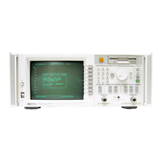
- Page 4 HP 8711C andHP 8713C RF Network Analyzers The HP 8711C and HP 8713C are easy-to-use RF network analyzers optimized for production measurements of reflection and transmission parameters. The instrument integrates an RF synthesized source, transmission/reflection test set, multi-mode receivers, and display in one compact box.
- Page 5 How to Use This Guide The Erst 7 chapters of this guide explain how to perform measurements, calibrate the instrument, and use the most common instrument functions. Chapters 8 through 12 are reference material. Use these chapters to look up information such as front panel features, speciEc key functions and 深圳市盛腾仪器仪表有限公司...
-
Page 6: Table Of Contents
1. Installing the Analyzer Step 1. Check the Shipment ... . . Step 2. Meet Electrical and Environmental Requirements . Step 3. Check the Analyzer Operation ..Step 4. - Page 7 Calibrate For a Reflection Response Measurement . . , 3-25 DUT ... Connect the 3-27 View and Interpret the Reflection Measurement Results 3-28 Making a Power Measurement using Broadband Detection 3-30 Enter the Measurement Parameters .
- Page 8 ... . To Turn Off Spur Avoidance To Avoid Frequency Bandcrossings by Minimizing the Span (HP 8713C only) ... . . 5-10 Increasing Network Analyzer Dynamic Range .
- Page 9 To Reduce the Receiver Noise Floor ..5-11 Reducing Trace Noise ... . 5-13 . . . To Activate Averaging for Reducing Trace Noise 5-13 To Change System Bandwidth for Reducing Trace Noise 5-14...
- Page 10 Automating Measurements Configuring Your Test System ... . Measurement System Topology ... 7-12 Expandability and Large Systems ..7-12 Throughput Considerations .
- Page 11 ..... 7-69 Markers 7-71 Title and Clock ....7-72 Saving Measurement Results .
- Page 12 ......9-45 ......9-53 0 .
- Page 13 1 l-6 Notice for Germany: Noise Declaration . 11-6 Declaration of Conformity ... . 12. Preset State and Memory Allocation 12-2 Preset and Peripheral States ..12-2 .
- Page 14 Ventilation Clearance Requirements ... . Analyzer Rear Panel Line Module and Selected Connectors . 1-13 HP-IB Connection Configurations ... . . Maximum and Minimum Protrusion of Center Conductor From Mating Plane .
- Page 15 Contents 4-2. Connect the Filter to the Analyzer ... . 4-3. Markers at Minimum and Maximum Values ..4-4. Peak and Minimum Search Criteria ... . 4-5.
- Page 16 8-2. Analyzer Connectors - Rear Panel ... . . 8-3. HP-IB Connector and Cable ....
- Page 17 1-14 l-l. Maximum HP-IB Cable Lengths ....3-16 4-71 4-1. Disk Access ......
-
Page 18: Installing The Analyzer
Installing the Analyzer 深圳市盛腾仪器仪表有限公司 Tel:0755-83589391 Fax:0755-83539691 Website: www.Sengt.c... - Page 19 Installing the Analyzer This chapter will guide you through the four steps needed to correctly and safely install your network analyzer. The four steps are: 1. Check the Shipment 2. Meet Electrical and Environmental Requirements 3. Check the Analyzer Operation 4.
-
Page 20: Step 1. Check The Shipment
After you have unpacked your instrument, it is recommended that you keep the packaging materials so they may be used if your instrument should need to be returned for maintenance or repair. Check the items received against the Product Checklist (included in your shipment) to make sure that you received everything. -
Page 21: Step 2. Meet Electrical And Environmental Requirements
1. Set the line voltage selector to the position that corresponds to the ac power source you will be using. Before switching on this instrument, make sure that the line voltage selector C A U T I O N switch is set to the voltage of the power supply and the correct fuse (T 5A 250 V) is installed. - Page 22 installing the Analyzer Step 2. Meet Electrical and Environmental Requirements 2. Ensure the available ac power source meets the following requirements: If the ac line voltage does not fall within these ranges, an autotransformer that provides third wire continuity to ground should be used. 3.
-
Page 23: Protective Earth Ground
Installing the Analyzer Step 2. Meet Electrical and Environmental Requirements 4. Verify that the power cable is not damaged, and that the power source outlet provides a protective earth ground contact. Note that the following illustration depicts only one type of power source outlet. Refer to Figure 8- 11 to see the different types of power cord plugs that can be used with your analyzer. -
Page 24: Ventilation Clearance Requirements
Installing the Analyzer Step 2. Meet Electrical and Environmental Requirements If this instrument is to be energized via an external autotransformer for W A R N I N G voltage reduction, make sure that its common terminal is connected to a neutral (earthed pole) of the power supply. - Page 25 7. Set up a static-safe workstation. Electrostatic discharge (ESD) can damage or destroy components. table mat with earth ground wire: HP part number 9300-0797 . wrist-strap cord with 1 Meg Ohm resistor: HP part number 9300-0980 HP pert number 9300-1367...
-
Page 26: Step 3. Check The Analyzer Operation
1. Turn on the line switch of the analyzer. After approximately 30 seconds, a display box should appear on the screen with the following information: The model number of your analyzer (either HP 8711C or HP 8713C) The firmware revision... -
Page 27: Step 4. Configure The Analyzer
You can begin making measurements by simply connecting your analyzer to an appropriate power source and turning it on. This section, however, will explain how to connect common peripherals and controllers, and how to install your analyzer into a rack system. 深圳市盛腾仪器仪表有限公司... -
Page 28: Connecting Peripherals And Controllers
D E T E C T O R S Figure 1-4. Analyzer Rear Panel line Module and Selected Connectors Refer to Figure l-4: The HP-IB port is for use with computers and peripherals (printers, plotters, etc.) The parallel and RS-232 (serial) ports are also for peripherals. With Option 深圳市盛腾仪器仪表有限公司... - Page 29 Installing the Analyzer Step 4. Configure the Analyzer general I/O control. See the User’s Handbook for information on using IBASIC. The VIDEO OUT COLOR VGA port allows you to connect a color VGA monitor for enhanced viewing. See “Using an External VGA Monitor” in Chapter 4 for more information.
-
Page 30: Hp-Ib Connection Configurations
Installing the Analyzer Step 4. Configure the Analyzer HP-IB Connections An HP-IB system may be connected in any configuration as long as the following rules are observed: The total number of devices is less than or equal to 15. The total length of all the cables used is less than or equal to 2 meters times the number of devices connected together up to an absolute maximum of 20 meters. -
Page 31: L-L. Maximum Hp-Ib Cable Lengths
Installing the Analyzer Step 4. Configure the Analyzer Table l-l. Maximum HP-IB Cable Lengths in System Between Each Pair of Devices Fifteen (maxl 20 m ltotall Parallel and Serial Parallel and serial devices often require speciEc cables-check their manuals Connections for details. - Page 32 (Eve), so changing the address is probably not necessary. To change the recognized address, press Printer HP-I3 Addr (&I Enter Only one hardcopy HP-IB address can be set at a time. Changing the printer address, for example, changes the plotter to the same address.
- Page 33 Select . LAN Printer (Option lF7 only): press IjHARDCOPY) Select Capy Port , use the entry controls to highlight HP LaserJet PCL5/6 PCL5 LAN, and press Select . If the printer IP address at the top of the screen is incorrect, press LAN Printer IP Addr to enter the correct IP address.
-
Page 34: Installing The Analyzer In A Rack
(handles) only. This rack mount kit allows you to mount the analyzer with or without handles. To install the network analyzer in an HP 85043D rack, follow the instructions in the rack manual. To install the network analyzer in other racks, note that they may promote... -
Page 35: Preventive Maintenance
Preventive maintenance consists of two tasks. It should be performed at least every six months-more often if the instrument is used daily on a production line or in a harsh environment. Clean the CRT Use a soft cloth and, if necessary, a mild cleaning solution. Check the RF Front Visually inspect the front panel connectors. -
Page 36: Getting Started
深圳市盛腾仪器仪表有限公司 Tel:0755-83589391 Fax:0755-83539691 Website: www.Sengt.com... -
Page 37: Network Analyzer Front Panel Features
Getting Started The HP 8711C and HP 8713C are easy-to-use, fully integrated RF component test systems. Each instrument includes a synthesized source, wide dynamic range receivers and a built-in test set. Controls are grouped by functional block, and settings are displayed on the instrument CRT. This section familiarizes new users with the layout of the front panel and the process of entering measurement parameters into the analyzer. -
Page 38: Front Panel Tour
6 SYSTEM The system keys control system level functions. These include instrument preset, save/recall, and hardcopy output. HP-W parameters and IBASIC are also controlled with these system keys. 7 The Numeric Keypad Use the number keys to enter a specific numeric value for a chosen parameter. Use the You can also use the front panel knob for making continuous adjustments to parameter values, while the @ and @ keys allow You to change values in steps. -
Page 39: Entering Measurement Parameters
This section describes how to input measurement parameter information into the network analyzer. N O T E When entering parameters, you can use the numeric key pad, as described in each example, or you can use the m a keys or the front panel knob to enter data. N O T E When you are instructed to enter numeric values in this manual, it often can get cluttered and confusing to depict each key stroke. -
Page 40: Connect The Filter To The Analyzer
Getting Started Entering Measurement Parameters N E T W O R K A N A L Y Z E R Figure 2.2. Connect the Filter to the Analyzer 深圳市盛腾仪器仪表有限公司 Tel:0755-83589391 Fax:0755-83539691 Website: www.Sengt.co... - Page 41 0 dBm Reference Level System Bandwidth Medium Wide HP 8711C only HP 8713C only 3 Preset power level can be set to other than 0 dBm if desired. See “Entering Source Power Level,” later in this chapter for more information.
- Page 42 Getting Started Entering Measurement Parameters Entering Frequency 1. Press the (FREQ) key to access the frequency softkey menu. Range softkeys. For instance if you set the center frequency to 160 MHz and the span to 300 MHz, the resulting frequency range would be 10 to 310 MHz. N O T E When entering frequencies, be sure to terminate Your numeric entry with the appropriate softkey to obtain the correct units.
- Page 43 Getting Started Entering Measurement Parameters Entering Source Power 1. Press the (POWER) key to access the power level softkey menu. level N O T E Your analyzer’s power level (depending upon its option configuration) may not be settable to below 4.
- Page 44 Getting Started Entering Measurement Parameters Scaling the 1. Press the Cm] key to access the scale menu. Measurement Trace 2. To view the complete measurement trace on the display, press Enter. 4. To move the reference position (indicated by the ) symbol on the left side of the display) to the first division down from the top of the display, press Reference Pusition (?iJ Enter.
- Page 45 Getting Started Entering Measurement Parameters Entering the Active The (MEAs] and (MEAS] keys allow you to choose which measurement Measurement Channel channel is active, and measurement parameters for that channel. When a and Type of particular measurement channel is active, its display is brighter than the Measurement inactive channel, and any changes made to measurement parameters will affect only the active measurement channel.
-
Page 46: Both Measurement Channels Active
Getting Started Entering Measurement Parameters L o g M a g 1 0 . 0 0 . 0 0 L o g M a g 1 0 . 0 dB/ R e f 0 . 0 0 - 1 0 - 2 0 - 3 0 - 4 0... -
Page 47: Split Display
Getting Started Entering Measurement Parameters Viewing Measurement To view only the measurement channel 2 reflection measurement press Channels To view both measurement channels again, press @iEKE). To view both measurement channels separately on a split screen, press 0 . 0 0 L o g M a g 1 0 . -
Page 48: Performing The Operator's Check
The operator’s check should be performed when you receive your instrument, and any time you wish to have confidence that the analyzer is working properly. The operator’s check does not verify performance to specifications, but should give you a high degree of confidence that the instrument is performing properly if it passes. -
Page 49: Equipment List
SO.75 dB of insertion loss from 1.3 to 3.0 GHz. A known good load (> 40 dB return loss) that matches the test port impedance of your analyzer such as one from calibration kit HP 85032B/E (50 a2) or HP 85036BiEI (75 0). 2-14 深圳市盛腾仪器仪表有限公司... -
Page 50: Make A Transmission Measurement
Getting Started Performing the Operator’s Check 1. Connect the equipment as shown in Figure 2-6. Use a known good cable such as the one that was supplied with your analyzer. N E T W O R K A N A L Y Z E R R F O U T Figure 2-6. -
Page 51: Verify Transmission Measurement
Getting Started Performing the Operator’s Check 0 . 1 d0/ R e f Log Mag 0 . 0 0 d0 s t o p 3 0 0 0 . 0 0 0 MH7 Figure 2-7. Verify Transmission Measurement N O T E The quality of the cable will affect this measurement;... -
Page 52: Make A Reflection Measurement
Getting Started Performing the Operator’s Check Leave the cable connected to the analyzer. Press (MEAS) Ref lectkan (EXE] Ilo] Enter Verify that the data trace falls completely below -16 dB. See Figure 2-8 for a typical result. Reflection Log Mag 10.0 dB/ Ref 0.00 dB O f f... -
Page 53: Connect The Load
Getting Started Performing the Operator’s Check L O A D Figure 2.9. Connect the load 5. Verify that the data trace falls below -30 dB. If the data trace is off the screen, press (??KF) Bef erence Level and the (IJJ key until the trace moves up onto the screen. -
Page 54: If The Analyzer Fails The Operator's Check
Getting Started First, repeat the operator’s check using a different cable and load to eliminate these as a possible cause of failure. If your analyzer does not meet the criteria in the operator’s check, your analyzer may need adjustment or servicing. Have a qualified service technician check the instrument or contact any Hewlett-Packard Sales or Service Office for assistance. -
Page 55: Making Measurements
Making Measurements 深圳市盛腾仪器仪表有限公司 Tel:0755-83589391 Fax:0755-83539691 Website: www.Sengt.c... - Page 56 Making Measurements This chapter provides an overview of basic network analyzer measurement theory, a section explaining the typical measurement sequence, a segment describing the use of the @EiK) key, and detailed examples of the following measurements: Measuring Transmission Response Measuring Reflection Response Making a Power Measurement using Broadband Detection Measuring Conversion Loss Measuring AM Delay (Option 1DA or 1DB)
-
Page 57: Measuring Devices With Your Network Analyzer
This section provides a basic overview of how the network analyzer measures devices. The analyzer has an RF signal source that produces an incident signal that is used as a stimulus to the device under test. Your device responds by reflecting a portion of the incident signal and transmitting (or perhaps altering and transmitting) the remaining signal. - Page 58 Making Measurements Measuring Devices with Your Network Analyzer Refer to Figure 3-2 for the following discussion regarding detection schemes and modes. The transmitted signal (routed to input B) and the reflected signal (input A) are measured by comparison to the incident signal. The network analyzer couples off a small portion of the incident signal to use as a reference signal (routed to input R).
-
Page 59: Simplified Block Diagram
Making Measurements Measuring Devices with Your Network Analyzer T r a n s m i s s i o n T e s t Figure 3-2. Simplified Block Diagram 3 - 5 深圳市盛腾仪器仪表有限公司 Tel:0755-83589391 Fax:0755-83539691 Website: www.Sengt.c... - Page 60 Making Measurements Measuring Devices with Your Network Analyzer Refer to Figure 3-3 for the following discussion. The network analyzer receiver has two signal detection modes: broadband detection mode narrowband detection mode There are two internal broadband detector inputs: B* and R*. External broadband detectors can also be used when connected to the X and Y ports on the rear panel of the analyzer.
-
Page 61: Block Diagram
Making Measurements Measuring Devices with Your Network Analyzer E x t e r n a l D e t e c t o r s Input R E A R P A N E L C R T F R O N T P A N E L R e f l e c t i o n Figure 3-3. - Page 62 Making Measurements Measuring Devices with Your Network Analyzer The following table shows the correlation between different types of measurements, input channels and signals. Measurement Detection Mode Input Channels Input Signals Transmission Narrowband transmitted/incident reflected/incident Reflection Narrowband Power Broadband transmitted/incident Conversion loss Broadband 深圳市盛腾仪器仪表有限公司...
-
Page 63: When To Use Attenuation And Amplification In A Measurement Setup
Making Measurements Measuring Devices with Your Network Analyzer When to Use For accurate measurements, use external attenuation to limit the power at Attenuation the RF IN port to + 10 dBm (for narrowband measurements) or + 16 dBm (for broadband measurements). Always use attenuation on the TRANSMISSION RF IN port if your test C A U T I O N... -
Page 64: When To Change The System Impedance
Making Measurements Measuring Devices with Your Network Analyzer Analyzers with a system characteristic impedance of 50 or 75 ohms, may be switched to the alternate impedance. If using minimum loss pads for impedance conversions, the alternate impedance should be selected so that the measurement results are displayed relative to the conversion impedance. -
Page 65: The Typical Measurement Sequence
Making Measurements Measuring Devices with Your Network Analyzer A typical measurement consists of performing four major steps: Step 1. Enter the The easiest way to set up the analyzer’s parameters for a simple Measurement measurement is to use the t-1 key. (See “Using the BEGIN Key to Make Parameters Measurements,”... -
Page 66: Using The Begin Key To Make Measurements
BEG IN Figure 3-4. The IBEGIN) Key The (jBEG’N) key allows you to quickly and easily conEgure the analyzer (from the [PRESET] condition) to measure the following devices: broadband passive devices cables (Option 100 only) correct instrument set up. The analyzer guides you through the initial steps and conEgures itself for the device type you select. -
Page 67: Key Overview
Making Measurements Using the BEGIN Key to Make Measurements The IBEGIN_) key sets up a generic instrument state for the testing of various types of devices. The @FX’) key has two different behaviors, depending on whether you are measurement selecting a device type, or a new type. - Page 68 Making Measurements Using the BEGIN Key to Make Measurements N O T E If the new measurement selected is a broadband measurement such as power, conversion loss, or AM delay, the start frequenn/ is limited to at least 10 MHz. Therefore, if your customized setup contains a start frequency below 10 MHz and you choose power, conversion loss, or AM delay, the start frequency will be changed to 10 MHz.
-
Page 69: Using The [Begin) Key To Configure Measurements . . . The User Begin Function (Option Lc2 Only)
Making Measurements Using the BEGIN Key to Make Measurements This procedure shows you how to configure the network analyzer for measurements. Press (PRESET). Presetting the instruments puts it into a known state with predefined parameters. Press @?%I) and then use a softkey to select the type of device that you will be measuring (amplifier, filter, broadband passive device, mixer, or cable). - Page 70 Medium Wide Narrow Wide 1 Options IDA and 106 only HP 8711C HP 8713C Preset Pwr 4 Preset power level is user-defined by using the 5 Maximum power is dependent upon the option configuration of your analyzer. See Chapter 10 to determine the maximum specified power for your analyzer.
- Page 71 Making Measurements Using the BEGIN Key to Make Measurements The User 3EGIN softkey gives you the capability to redefine the [BEGIN] key menu and install user-dellned macro functions. The User BEGIN key is only available if your analyzer has IBASIC (Option lC2) installed. Use this key to define macros such as: save/recall Macros must be defined within an IBASIC program.
-
Page 72: Measuring Transmission Response
This section uses an example measurement to describe how to calibrate for and make a basic transmission response measurement. In this example, a used. Press (m’ on the analyzer to set the analyzer to the default mode which includes measuring transmission on measurement channel 1. N O T E This example measurement uses the default instrument parameters for a transmission measurement. -
Page 73: Calibrate For A Transmission Response Measurement
Making Measurements Measuring Transmission Response Your analyzer can provide highly accurate measurements without performing any additional user-calibrations if certain conditions are met. This example describes how to perform an enhanced transmission response calibration. When you perform an enhanced transmission response calibration, the analyzer performs correction at the selected number of data points across the selected frequency band. - Page 74 Making Measurements Measuring Transmission Response 4. The analyzer will measure each standard and then calculate the new calibration coefficients. The message “Calibration complete . x will appear for a few seconds when the analyzer is done calculating the new error correction array. 5.
-
Page 75: Connect The Dut
Making Measurements Measuring Transmission Response D E V I C E U N D E R T E S T Figure 3-5. Equipment Setup For a Transmission Response Measurement 3 - 2 1 深圳市盛腾仪器仪表有限公司 Tel:0755-83589391 Fax:0755-83539691 Website: www.Sengt.c... -
Page 76: View And Interpret The Transmission Measurement Results
Making Measurements Measuring Transmission Response 1. To view the entire measurement trace on the display, press 2. To interpret the transmission measurement, refer to Figure 3-6 or your analyzer’s display if you are making this measurement on your instrument. a. The values shown on the horizontal axis are the frequencies in MHz. The values shown on the vertical axis are the power ratios in decibels incident power. -
Page 77: Example Of A Transmission Measurement Display
Making Measurements Measuring Transmission Response 20.0 -60.00 L o g M a g o f f 6 9 . 2 6 - 1 2 0 - 1 4 0 A b s S t o p 3 0 0 0 0 0 0 MHz 0 . -
Page 78: Measuring Reflection Response
This section uses an example measurement to describe how to calibrate for and make a basic reflection response measurement. In this example, a used. Press the following keys on the analyzer: This example measurement uses the default instrument parameters for a reflection response measurement. -
Page 79: Calibrate For A Reflection Response Measurement
To perform a reflection one-port calibration you will need one of the following calibration kits depending on the nominal impedance of your analyzer: for 50 62 type-N female connector calibrations HP 850323 for type-N female or type-N male 50 61 connector calibrations HP 85032B... -
Page 80: Equipment Setup For A Reflection Response Calibration
Making Measurements Measuring Reflection Response Chapter 6 provides detail about when this calibration is necessary. If you wish to calibrate your instrument for a reflection one-port measurement, perform the following steps: 2. The instrument will prompt you to connect three standards (open, short and load) and measure them. -
Page 81: Connect The Dut
Making Measurements Measuring Reflection Response N E T W O R K A N A L Y Z E R N E T W O R K A N A L Y Z E R L O A D Figure 3-8. Equipment Setup For a Reflection Measurement of a Two-Port Device N E T W O R K A N A L Y Z E R D E V I C E U N D E R TESl Figure 3.9. -
Page 82: View And Interpret The Reflection Measurement Results
Making Measurements Measuring Reflection Response 1. To view the entire measurement trace on the display, press @ZiE] Autoscale. 2. To interpret the reflection measurement, refer to Figure 3-10 or your analyzer’s display if you are making this measurement on your instrument. -
Page 83: Example Of A Reflection Measurement Display
Making Measurements Measuring Reflection Response -15.00 L o g M a g 5 . 0 R e f o f f - 1 0 C h l - 2 0 - 2 5 - 3 5 I S t a r t 0 . 3 0 0 M H z Figure 3-10. -
Page 84: Making A Power Measurement Using Broadband Detection
Power measurements can be made using either narrowband or broadband detection. The example in this section is of a broadband power measurement. If you are only interested in the output power of your device at the same frequency as the analyzer’s source, you can select (MEAS] Detection Options Narrowband Internal B for a narrowband power measurement. -
Page 85: Enter The Measurement Parameters
Making Measurements Making a Power Measurement using Broadband Detection Press the following keys on the analyzer: Power N O T E This example measurement uses the default instrument parameters for a power measurement. If your particular power measurement requires specific parameters [such as frequency range, source power level, number of data points, and sweep time) enter them now Damage to your analyzer will occur if the receiver input power exceeds C A U T I O N... -
Page 86: Connect The Dut
Making Measurements Making a Power Measurement using Broadband Detection T E S T Figure 3-11. Equipment Setup For a Power Measurement 3 - 3 2 深圳市盛腾仪器仪表有限公司 Tel:0755-83589391 Fax:0755-83539691 Website: www.Sengt.c... -
Page 87: View And Interpret The Power Measurement Results
Making Measurements Making a Power Measurement using Broadband Detection 2. Figure 3-12 shows the results of an example power measurement. 3. To interpret the power measurement, refer to Figure 3-12 or your analyzer’s display if you are making this measurement on your instrument. -
Page 88: Example Of A Power Measurement
Making Measurements Making a Power Measurement using Broadband Detection L o g M a g 0 . 5 R e f 5 . 0 0 dBm o f f S t a r t 1 0 . 0 0 0 MHz Figure 3-12. -
Page 89: Measuring Conversion Loss
Conversion loss is the ratio of IF output power to RF input power expressed in dB. This section uses an example measurement to describe how to measure the conversion loss of a broadband mixer. When characterizing a device’s conversion loss, the analyzer uses broadband detection to compare the transmitted signal (B*) to the reference signal (R*). -
Page 90: Filtering Out The Unwanted Mixing Product
Making Measurements Measuring Conversion Loss 7 0 0 M H z 2 0 0 7 0 0 ( R F - L O ) ( R F ) (RF+LO) 2 0 0 Figure 3-13. Filtering Out the Unwanted Mixing Product Inserting a 700 MHz bandpass filter in the measurement setup removes the unwanted signals at 200 MHz, 900 MHz and 1100 MHz, providing an accurate measurement of the desired IF signal at 700 MHz. -
Page 91: Enter The Measurement Parameters
Making Measurements Measuring Conversion Loss Press the following keys on the analyzer: This example measurement uses the default instrument parameters for a conversion loss measurement. If your particular conversion loss measurement requires specific parameters (such as frequency range, source power level, number of data points, and sweeptime) enter them now 3 - 3 7 深圳市盛腾仪器仪表有限公司... -
Page 92: Perform A Normalization Calibration
Making Measurements Measuring Conversion loss Normalization is the simplest type of calibration. The analyzer stores normalized data into memory and divides subsequent measurements by the stored data to remove unwanted frequency response errors. This calibration is used for this measurement to remove the insertion loss error of the IF filter. -
Page 93: Connect The Dut
Making Measurements Measuring Conversion loss N E T W O R K A N A L Y Z E R OSC I LLATOR * F i l t e r a t I F f r e q u e n c y r e m o v e s u n w a n t e d m i x i n q p r o d u c t s . -
Page 94: View And Interpret The Conversion Loss Results
Making Measurements Measuring Conversion loss 2. To interpret the conversion loss measurement, refer to Figure 3-15 or your analyzer’s display if you are making this measurement on your instrument. a. The values shown on the horizontal axis represent the source RF output. -
Page 95: Example Of A Conversion Loss Measurement
Making Measurements Measuring Conversion loss 0 . 2 - 6 . 8 0 dB d a t a - 6 . 2 C e n t e r 9 0 0 . 0 0 0 M H z S p a n 1 5 . 0 0 0 M H z Figure 3-15. - Page 96 An AM delay measurement characterizes the group delay (or envelope delay) of a device. lb perform this measurement you must have ordered either Option 1DA (AM Delay, 50 ohm) or Option 1DB (AM Delay, 75 ohm). These options include internal instrument hardware and hrmware, two external scalar detectors and a power splitter.
-
Page 97: Measuring Am Delay (Option 1Da Or 1Db)
Making Measurements Measuring AM Delay (Option 1 DA or 1 DE1 Connect the detectors and power splitter to the analyzer as shown in Figure 3-16 and then press the following keys on the analyzer: [PRESET) You may also press the following keys to access AM delay. Pressing these keys will result in a connection diagram being displayed on the screen of the This example measurement uses the default instrument parameters for an AM delay measurement. -
Page 98: Calibrate For An Am Delay Measurement
Making Measurements Measuring AM Delay (Option 1 DA or 1 DB) 1. Connect the equipment as shown: NETWORK A N A L Y Z E R 1 Figure 3-l 6. Equipment Setup For an AM Delay Response Calibration Press [CAL) Respmse Measure Staxxdard . 3-44 深圳市盛腾仪器仪表有限公司... - Page 99 深圳市盛腾仪器仪表有限公司 Tel:0755-83589391 Fax:0755-83539691 Website: www.Sengt.com...
-
Page 100: View And Interpret The Am Delay Results
Making Measurements Measuring AM Delay (Option 1 DA or 1DBI This example is an AM delay measurement of a frequency converter. 2. To interpret the AM delay measurement, refer to Figure 3-18. a. Note that the vertical axis is displaying time rather than power as in previous example measurements. -
Page 101: Example Of An Am Delay Measurement
Making Measurements Measuring AM Delay (Option 1 DA or 1 DB) 1.46 R e f 5 5 . 6 kHz o f f C h l : M r l I 1 . 4 5 1 . 3 8 A b s S p a n 8 . -
Page 102: Making Measurements With The Auxiliary Input
The auxiliary input (AUX INPUT) is located on the rear panel of your analyzer. This input is designed to monitor sweep related dc control signals of devices generally used in conjunction with the analyzer, such as a dc-biased amplifier, or a Voltage Controlled Oscillator (VCO). The AUX INPUT is recommended for use as an oscilloscope, for several reasons. - Page 103 Using Instrument Functions 深圳市盛腾仪器仪表有限公司 Tel:0755-83589391 Fax:0755-83539691 Website: www.Sengt.com...
- Page 104 Using Instrument Functions This chapter explains some common analyzer functions that can help you to examine, store, and print measurement data. The following functions are explained in this chapter: Using Markers Using Reference Tracking Customizing the Display Saving and Recalling Measurement Results Connecting and Configuring Printers and Plotters Printing and Plotting Measurement Results Using a Keyboard...
- Page 105 The markers provide numerical readout of trace data. Markers have a stimulus value (the x-axis value) and a response value (the y-axis value). When you switch on a marker, and no other function is active, the analyzer shows the marker stimulus value in the active entry area. You can control markers with the front panel knob, the step keys, or the front panel numeric keypad.
-
Page 106: Using Instrument Functions Using Markers
Using Instrument Functions Using Markers If a marker is on, two lines of numbers follow the marker annotation: the upper line indicates the frequency in MHz, and the lower line indicates the magnitude. The examples in this section are shown with a transmission response measurement of a filter. -
Page 107: To Activate Markers
Using Instrument Functions Using Markers 1. Press the (Wj key to activate marker 1. 2. lb activate markers 2 through 4, use the softkeys. For example, press press Edor~ Ma&e~ct and then the softkey that corresponds to the marker you wish to activate. 3. -
Page 108: To Turn Markers Off
Using Instrument Functions Using Markers 1. All markers can be turned off by pressing C-1 811 Off 2. ‘lb turn off an individual marker, make it the active marker by pressing its corresponding softkey, and then press &%iv& Mxrksr Off (accessed by pressing MWS~ Mzkrkerg if necessary). - Page 109 Using Instrument Functions Using Markers Markers can be used to: automatically calculate bandwidth or notch parameters of lilters automatically search for multiple maximums or minimums N O T E Marker tracking can be useful for tuning OUTS when combined with the marker search functions. When tracking is turned on, the marker search is applied to the active marker and is updated with each sweep.
- Page 110 Using Instrument Functions Using Markers The maximum search functions search for peak points on the measurement Win Search trace. The minimum search functions search for minimum points on the measurement trace. Press (j-j Maker Ssarch #in Ssaxh MErr -> #$n to place marker 1 at the minimum value on the trace.
- Page 111 Using Instrument Functions Using Markers Using the Next Peak and Next Min Functions. As explained previously, pressing W -> Max and Mkr -> Min will place a marker on the maximum and minimum points on the measurement trace, respectively. You can search for the next highest or lowest point using the Hex% Peak Right , Hex% Peak Left , ??a~?z Min Righ% and A maximum (or minimum) point is detected whenever an amplitude excursion greater than half of a division occurs.
- Page 112 Using Instrument Functions Using Markers Criteria Figure 4-5. Peak and Minimum Search Criteria at Display Endpoints 4 - 1 0 深圳市盛腾仪器仪表有限公司 Tel:0755-83589391 Fax:0755-83539691 Website: www.Sengt.com...
- Page 113 Using Instrument Functions Using Markers To Search for Target Values value. (The default value is -3 dB.) of the target value to the right. The target value is in reference to 0 dE% 4. Press Search Left and notice the marker moves to the Iirst occurrence of the target value to the left.
- Page 114 Using Instrument functions Using Markers To Search for Bandwidth Values N O T E The bandwidth search function is intended for transmission or power measurements in log mag format only. The bandwidth search feature analyzes a bandpass hlter and calculates the bandwidth, center frequency, and Q (see note below) for the specified bandwidth level.
- Page 115 Using Instrument Functions Using Markers Dedicated Use of Markers in Bandwidth Search Mode Dedicated Use Measurement Channel 1 Measurement Channel 2 maximum power value marker 1 marker 2 center frequency of pass bend’ marker 3 marker 4 bandwidth cutoff ooint lleftl marker 5 marker 7 bandwidth cutoff point lrightl...
- Page 116 Using Instrument Functions Using Markers To Search for Notch Values N O T E The notch search function is intended for transmission or power measurements in log mag format only 1. To follow along with this example you will need to connect a notch filter to the analyzer in place of the bandpass filter shown in Figure 4-2.
- Page 117 Using Instrument Functions Using Markers Dedicated Use of Markers in Notch Search Mode Dedicated Use Channel 1 I Measurement Channel 2 I marker 1 marker 2 center frequency of stop band’ marker 3 marker 4 notch -n dB point* Ileftl marker 5 marker 7 notch -n dB point* lrightl...
- Page 118 Using Instrument Functions Using Markers To Use Multi-Peak or Multi-peak and multi-notch searches are designed for use when measuring Multi-Notch Search multi-pole Elters. Both searches automatically search the measurement trace from left to right, and position a marker at each local maximum or minimum. Up to eight maximums or minimums will be found.
- Page 119 Using Instrument Functions Using Markers When the maximum or minimum point is at or near either edge of the display, the excursion requirement is satisEed by a half of a division excursion on just one side of the maximum (or minimum). See Figure 4-9. Both Meet End Peak Criteria...
- Page 120 Using Instrument Functions Using Markers 2 . 0 L o g M a g -5.00 - 1 1 - 1 3 - 1 5 - 1 7 A b s S t o p 5 0 0 . 0 0 0 M H z S t a r t 1 0 .
- Page 121 Using Instrument Functions Using Markers L o g M a g 5 . 0 1.00 Chl ) -’ - C h l ; M k r l - 1 9 - 2 4 - 2 9 - 3 4 - 3 9 S t a r t I O ,000 M H z S t o p 5 0 0 .
-
Page 122: To Use Marker Math Functions
Using Instrument Functions Using Markers The three marker math functions: statistics, flatness, and RF filter stats, perform certain mathematical calculations on the amplitude data of user-defined trace segments. For measurement channel 1, the trace segment is dehned with markers 1 and 2;... - Page 123 Using Instrument Functions Using Markers 3. Figure 4-12 shows a deEned trace segment. Notice the marker readout in the upper right corner of the display. 0 . O o dB 0 . 5 L o g Mag o f f C h l M e a n : - 2 .
- Page 124 Using Instrument Functions Using Markers To Use Marker Flatness The marker flatness search function measures a user-defined segment of the measurement trace and calculates the following: The analyzer calculates flatness by drawing a straight line between the markers. A maximum vertical deviation from this line is computed for each measurement point.
- Page 125 Using Instrument Functions Using Markers L o g Mag 0 . 5 0 .OO d8 s o n: 4 4 . 6 1 M H 1 5 4 . 1 5 - 2 . 9 7 dB - 2 . 9 7 - 0 .5.1 d8 1 .
- Page 126 Using Instrument Functions Using Markers To Use RF Filter The RF filter statistics function measures both the passband and the stopband Statistics (reject-band) of a Elter with a single sweep. 1. On measurement channel 1 press (WJ and place marker 1 at the beginning of the passband and marker 2 at the end of the passband.
- Page 127 Using Instrument Functions Using Markers 5 . 0 - 2 5 . 0 0 L o g Mag - 4 . 2 6 - 4 . 1 8 - 4 5 . 9 5 - 4 0 . 7 0 M a r k e r s M a r k e r F u n c t Ions...
-
Page 128: To Use Delta (A) Marker Mode
Using Instrument Functions Using Markers In marker delta mode, a reference marker is placed at the active marker position. All marker values are then displayed in reference to this delta marker. When the amplitude of the measurement trace changes, the reference marker value also changes. - Page 129 Using Instrument Functions Using Markers L o g M a g 2 0 . 0 S p a n 3 4 9 . 4 0 0 M H z C e n t e r 1 7 5 . 0 0 0 M H z Figure 4-15.
-
Page 130: To Use Other Marker Functions
Using Instrument Functions Using Markers To Use Marker to This function changes the analyzer’s center frequency to that of the active Center Frequency marker and limits the span if necessary. If the markers are all off, and this function is selected, it first turns on marker 1 at its previous setting or, if no previous setting, at the center frequency (default). -
Page 131: Using Limit Testing
Limit testing is a measurement technique that compares measurement data to constraints that you dehne. Depending on the results of this comparison, the analyzer can indicate if your device either passes or fails the test. Limit testing is useful for real-time tuning of devices to speciEcations. When limit testing is turned on, pass/fail results can be output to the display and also to the LIMIT TEST TTL IN/OUT connector on the rear panel. -
Page 132: To Create A Flat Limit Line
Using instrument Functions Using limit Testing In this example, you will create a minimum limit line from 155 MHz to 195 MHz at a level of -3 dB. 1. To access the limit line menu press ($EiZVJ Limft M%rtu . Line . - Page 133 Using Instrument Functions Using limit Testing N O T E You can move the position of the pass/fail indicator, turn on or off the pass/fail text, and turn on or off the fail icon in the limit options menu. Press For more information, see “Customizing the Displq”...
-
Page 134: To Create A Sloping Limit Line
Using Instrument Functions Using limit Testing A sloping limit line has different values for its begin and end limits. For example, create a sloping limit line between 130 MHz and 155 MHz with a beginning level of -35 dB and an ending level of -3 dB. Menu Add Limit Add N O T E... - Page 135 Using Instrument Functions Using limit Testing 5 . 0 - 1 5 . 0 0 L o g M a g - 1 0 - 2 0 - 2 5 - 3 0 - 3 5 A b s C e n t e r 1 7 5 . 0 0 0 M H z Figure 4-16.
-
Page 136: To Create A Single Point Limit
Using Instrument Functions Using limit Testing Sometimes you may only be interested in the level at one particular frequency. In this case, you may wish to use a single point limit. Using the setup from the previous examples and building on them, let’s assume that when testing your bandpass Elter, it is specified that the insertion loss at 174 MHz must be less than 3 dB. -
Page 137: To Use Marker Limit Functions
Using Instrument Functions Using limit Testing The following marker limit test types are available in the marker limit table: Statistic: Mean Delta Amp1 Delta Freq The first three items above are parameters of special marker functions. You can use pass/fail limit testing on three parameters of the marker math functions: statistical mean, peak-to-peak ripple, and flatness. - Page 138 Using Instrument Functions Using limit Testing Statistical Mean 1. This limit test requires that you first define a segment on the measurement trace using markers 1 and 2 (or markers 3 and 4 for measurement channel 2). Then press [MARKER) Mz~koz Functions M~&BZC Math Statistics”...
- Page 139 Using Instrument Functions Using limit Testing Peak-to-Peak Ripple This limit test requires that you first define a segment on the measurement trace using markers 1 and 2 (or markers 3 and 4 for measurement channel 2). Then press @iGZK] Mmk&r F~c%ions Mwksr Et&t& Statistics to enable the statistics marker search.
- Page 140 Using Instrument Functions Using limit Testing Flatness 1. This limit test requires that you Erst define a segment on the measurement trace using markers 1 and 2 (or markers 3 and 4 for measurement channel 2). Then press @ZGKK~ Marker Fun&ions M=k&r Math Flatness to enable the statistics marker search.
- Page 141 Using Instrument Functions Using limit Testing Delta Amplitude This marker limit test allows you to set marker 1 as an amplitude reference against which marker 2 is limit tested. This limit test requires that you Erst use marker 1 to determine the reference amplitude: Press (j-1 2: and then use the front panel knob or the Q) @J keys to place marker 1 at the desired place on the measurement trace.
- Page 142 Using Instrument Functions Using limit Testing Delta Frequency This marker limit test allows you to set marker 1 as a frequency reference against which marker 2 is limit tested. 1. This limit test requires that you first use marker 1 to determine the reference frequency: Press @iiKiS] 1: and then use the front panel knob or the 0) (JJ keys to place marker 1 at the desired place on the measurement trace.
-
Page 143: To Use Relative Limits
Using Instrument Functions Using limit Testing There may be times when you are interested in the shape of a measurement trace, but not concerned with the absolute amplitude. For example, Figure 4-16 shows limit lines created for tuning a filter to a particular shape. If the shape is more important than the amplitude, you can make the limit lines relative to the peak point of the trace using the reference tracking function. -
Page 144: Other Limit Line Functions
Using Instrument Functions Using limit Testing To Turn limit lines On Using the Limit Lins f3N off softkey toggles any created limit lines and Off on and off; it does not delete them. You can still use the limit test function (pass/fail) without the limit lines appearing on the display screen. - Page 145 Using Instrument Functions Using limit Testing To Move the Pass/Fail The limit test pass/fail indicator and text can be moved to any position on the Indicator Text and Icon display screen. lb move the position of the pass/fail indicator: can also place the indicator along the horizontal by entering a percentage using the numeric keypad.
-
Page 146: Additional Notes On Limit Testing
Using Instrument Functions Using limit Testing Stimulus end Amplitude In frequency sweep mode, the stimulus values are interpreted as frequencies; Values in power sweep mode, the stimulus values are interpreted as output power levels. The values entered for stimulus and amplitude are unitless. If the C A U T I O N measurement format is changed after limit lines are set, the amplitude values do not automatically change. - Page 147 Using Instrument Functions Using limit Testing Example 1. When using a small number of measurement points, limit lines must be set carefully, or the results may be confusing, because the analyzer connects the measurement points with straight lines. The following illustration shows a data trace with three measurement points: A, B, and C, along with a minimum limit line.
- Page 148 Using Instrument Functions Using limit Testing Example 2. In this example, the analyzer has been set up with the following parameters: Start frequency = 90 MHz Stop frequency = 210 MHz Number of points = 11 Maximum limit line begin frequency = 90 MHz Maximum limit line end frequency = 200 MHz Refer to the illustration below for the discussion.
-
Page 149: Using Reference Tracking
The reference tracking functions allow you to track either the peak point or a certain frequency of a measurement trace. It does this by adjusting the reference level with each sweep so that the point of interest always falls on the display reference line. -
Page 150: To Track The Peak Point
Using Instrument Functions Using Reference Tracking 1. If you want to move the reference position (indicated by the ) symbol on the left side of the display), press (SCALE] Befererzce Positioz~ and then use the front panel knob, the @) (IJJ keys, or the numeric keypad to enter a new reference position. -
Page 151: To Track A Frequency
Using Instrument Functions Using Reference Tracking 1. If you want to move the reference position (indicated by the ) symbol on the left side of the display), press (SCALE) Ref erez%te Position and then use the front panel knob, the m (IJJ keys, or the numeric keypad to enter a new reference position. -
Page 152: Customizing The Display
The analyzer’s display can be customized in several ways: You can choose to view one or both measurement channels using the split display feature. You can turn on or off features such as the display graticule and limit lines. You can expand the measurement display to the full screen size and eliminate all annotation except marker annotation. -
Page 153: Using The Split Display Feature
Using Instrument Functions Customizing the Display When using both measurement channels, you can choose to either view both of them simultaneously on full-size display, or use the split screen feature. 1 0 . 0 0 . 0 0 dB L o g M a g - 3 0 A b s S t a r t... -
Page 154: Enabling/Disabling Display Features
Using Instrument Functions Customizing the Display Figure 4-21 shows a display screen with graticule lines (the measurement grid), and two limit lines. In the default or preset state, these lines are turned 1 0 . 0 dB/ R e f - 2 4 . 6 0 d0 L o g M a g I i...i* Line... - Page 155 Using Instrument Functions Customizing the Display line or point on and off. Turning limit lines or points off does turn limit testing off. You cannot turn off the delta amplitude or delta frequency limit indicators. 4-53 深圳市盛腾仪器仪表有限公司 Tel:0755-83589391 Fax:0755-83539691 Website: www.Sengt.c...
-
Page 156: Modifying Display Annotation
Using Instrument Functions Customizing the Display When you fnxt turn on your analyzer, or use the @EET~ key to return it to the default condition, most of the display annotation is visible. You may want to modify or turn on or off some of the annotation to customize the display to your preferences. - Page 157 Using Instrument Functions Customizing the Display M e a s u r e m e n t Pass/Fail Marker Marker C h a n n e l Y-axis Title and Indicator Annotation N u m b e r Annotation Clock Annotation _ _ _ _ _ _ _ _ _ _ _ _ _ Frequency...
- Page 158 Using Instrument Functions Customizing the Display The following display annotation areas can be modsed or turned on or off: Measurement title and clock Measurement channel annotation Frequency annotation Marker annotation Marker number Y-axis labels Y-axis (relative or absolute scale) 4-56 深圳市盛腾仪器仪表有限公司...
- Page 159 Using Instrument Functions Customizing the Display Measurement title and The measurement title area consists of two lines of text. In the default clock or preset state, this annotation area is toggled off. When the title mode is initially turned on - by pressing @GG?) More Display Title and Clock - line 1 is empty and the clock (date and time of day) is assigned to line 2.
- Page 160 Using Instrument Functions Customizing the Display Marker Annotation The marker annotation that appears in the upper right corner of the display can be turned on or off by pressing (mj Mme Display Marker Number The marker numbers that appear above or below the marker symbols, can be turned on or off by pressing fjj) More Display Y-Axis Annotation Press (DISPLAY) Mar&...
-
Page 161: Expanding The Displayed Measurement
Using Instrument Functions Customizing the Display Normally, the displayed measurement is limited in size due to the softkey menu and the surrounding annotation. The expanded display feature removes these size-limiting factors, with the exception of annotation inside the normal graticule, and expands the display to the full screen size. The remaining annotation is enlarged for better readability. - Page 162 Using Instrument Functions Customizing the Display o f f L o g M a g 0 . 5 - 2 . O O dB s p a r : 5 5 . 7 1 8 0 . 5 1 7 4 8 2 .
- Page 163 Using Instrument Functions Customizing the Display Figure 4-24. Expanded Display 4 - 6 1 深圳市盛腾仪器仪表有限公司 Tel:0755-83589391 Fax:0755-83539691 Website: www.Sengt.c...
-
Page 164: Saving And Recalling Measurement Results
The network analyzer allows you to save the following information to internal memory or to a DOS-formatted disk in the analyzer’s built in 3.5” disk drive: Instrument Instrument state settings consist of all the stimulus and State response parameters that set up the analyzer to make a specific measurement including markers, limit lines, memory traces, and user-defined calibrations. - Page 165 Using Instrument Functions Saving and Recalling Measurement Results Special Note for HP 8711 A, HP 87118112811381148 Owners If you own one of these older model analyzers, there are some compatibility issues You should be aware of: The “A” and “B” model analyzers allowed you to save to a LIF formatted floppy disk. Your “C model analyzer allows you to read from a LIF disk, but you cannot save to a LIF disk.
-
Page 166: Saving Instrument Data
Using Instrument Functions Saving and Recalling Measurement Results When you save data to a Ele, the analyzer automatically selects a hle name for you. Since these names may not be as descriptive as desirable, you may change the name of the file after it has been saved, or you can save it to a fle name of your choice by using the Re-Saue %ate function. - Page 167 Using Instrument Functions Saving and Recalling Measurement Results Select the Disk 1. If you are using a floppy disk, place a DOS formatted disk in the disk drive you are using. If your disk is not formatted, refer to the procedure in “Formatting a Floppy Disk”...
- Page 168 The flename appears on the screen as STATEIt. STA (where # is a number the analyzer selects from 0 to 999). 3. If you own older model network analyzers (HP 8711A, HP 8711B/12B/13B/14B), and you need your saved files to be recalled on any of these older model analyzers, select File Format 4.
- Page 169 Using Instrument Functions Saving and Recalling Measurement Results To Save Measurement Your measurement data can be saved in an ASCII format that is compatible Data in ASCII Format with many personal computer software packages. lb save the measurement trace as an ASCII file: 1.
-
Page 170: To Recall From A Disk Or Internal Memory
Using Instrument Functions Saving and Recalling Measurement Results The network analyzer allows you to recall and display measurement results that you saved as STATE hles. You can then compare the recalled measurements to subsequent measurements. The analyzer can display both a data and memory trace for each measurement channel. The data trace is saved when you select Data iITs in the I&fine Save menu. -
Page 171: Other File Utilities
Using Instrument Functions Saving and Recalling Measurement Results To Rename a File 1. Press the disk where the desired file is located. 2. Use the front panel knob to move the highlighted bar to the file you want to rename. 3. - Page 172 Using Instrument Functions Saving and Recalling Measurement Results To Delete a File Highlight the Iile to be deleted by using the front panel knob or the m (JJ keys. Press N&&s File YES ‘lb delete all hles within the current directory, press IMete ALI. Fflos YES.
- Page 173 Saving and Recalling Measurement Results To Access Files From Files on each disk can be accessed via HP-R3 using SCPI commands, directly SCPI, IBASIC, or FTP from IBASIC (with Option lC2), or over a LAN (with Option lF7). The table below shows the names used for each disk.
-
Page 174: To Use Directory Utilities
Using Instrument Functions Saving and Recalling Measurement Results This section describes how to make directories so you can store files into categories, how to change between the various existing directories, and how to remove an unwanted directory. You can make directories for floppy disks and the analyzer’s internal memory, and RAM disk. - Page 175 Using Instrument Functions Saving and Recalling Measurement Results N O T E You can also change to a directory and use Make Directory to create a subdirectory The number of characters in a directory and subdirectory path cannot exceed the MS-DOS limitation of 63. Change to a Directory 1.
-
Page 176: Formatting A Floppy Disk
Using Instrument Functions Saving and Recalling Measurement Results You must format unformatted floppy disks before you can save data on them. The analyzer internal memory and RAM disk memory do not need to be formatted. AII information on the disk wiU be erased during the formatting process. C A U T I O N 1. -
Page 177: Connecting And Configuring Printers And Plotters
The analyzer supports HP-B, serial, parallel, and LAN (Option lF7 only) peripherals. Hardcopy output can also be saved to a file in either HP-GL or PCX format. With Option lF7, LAN capability, you can also capture hardcopy output in either HP-GL or PCX format. -
Page 178: Select A Compatible Printer Or Plotter
HP 7475A Six-Pen Graphics Plotter HP 755OA/B High-Speed Eight-Pen Graphics Plotter These printers are All HP LaserJets (LaserJet III, 4, and 5 support PCL5 for fastest hardcopies) compatible All HP DeskJets (HP DeskJet 1200C can also be used to plot) -
Page 179: Select An Appropriate Interface Cable
Using Instrument Functions Connecting and Configuring Printers and Plotters If your peripheral is to be connected to HP-IB, choose one of the following cables : HP 10833A HP-IB Cable, 1.0 m HP 10833B HP-II3 Cable, 2.0 m HP 10833D HP-II3 Cable, 0.5 m... -
Page 180: Connect The Printer Or Plotter
Using Instrument Functions Connecting and Configuring Printers and Plotters 1. Turn off the analyzer and the printer or plotter. 2. Connect to one of the ports shown in Figure 4-25. L A N S E R I A L E T H E R T W I S T P E R I P H E R A L P A R A L L E L H P - I B... -
Page 181: Configure The Hardcopy Port
HP Printer HP Printer Epson Compatible Epson Epson Compatible Epson File HPGL Internal Disk File tile HPGL File HP LaserJet PCLW PCL5 HP LaserJet PCL5/6 HP LaserJet PCL5/6 HP-IB HP LaserJet PCL5/6 only Option lF7 4-79 深圳市盛腾仪器仪表有限公司 Tel:0755-83589391 Fax:0755-83539691 Website: www.Sengt.c... - Page 182 Using Instrument Functions Connecting and Configuring Printers and Plotters The analyzer can send print commands in PCL5, PCL, Epson, or HP-GL modes. Recommended usages are: Use PCL5 mode for maximum speed, if your printer supports it. HP LaserJet lII/4/5 models support PCL5. Typical time to generate and send hardcopy output to a PCL5 printer is 1 to 10 seconds.
- Page 183 Select . Configuring the If your HP-IR printing/plotting device has a different address than the Analyzer for HP-IB analyzer default of 05, press Print/Plo% HP+-fl!$ Addr and enter...
-
Page 184: Define The Printer Or Plotter Settings
Using Instrument Functions Connecting and Configuring Printers and Plotters You will only have to do this setup once if you make all your hardcopies with the same printing or plotting device. Press (HARDCOPY) and then Define PCLS , Def in& Prizlter , or that only one of these choices is selectable at a time. - Page 185 Using instrument Functions Connecting and Configuring Printers and Plotters in mm. Minimum setting is 0.00 mm; maximum setting is 200.00 mm. printout in mm. Minimum setting is 0.00 mm; maximum setting is 200.00 mm. c. Print Width : Sets print width (printing space) of printout in mm. Minimum setting is SO mm;...
- Page 186 Using Instrument Functions Connecting and Configuring Printers and Plotters Defining a Printer Make the following selections in the analyzer menus: The defaults are: Default Parameter Monochrome/Color Monochrome Orientation Portrait Auto Feed Printer Resolution 96 Dots Per Inch Top Margin 0.00 mm Left Margin 0.00 mm Print Width...
- Page 187 Epson 60, 120, 240, 360 dpi. HP DeskJet 540 should not be used at 100 in mm. Minimum setting is 0.00 mm; maximum setting is 200.00 mm. printout in mm. Minimum setting is 0.00 mm; maximum setting is 200.00 mm.
- Page 188 Using Instrument Functions Connecting and Configuring Printers and Plotters Defining a Plotter Make the following selections in the analyzer menus: The defaults are: Default Monochrome Auto Feed Trace 1 - Pen 1 Color Plotter Pen Numbers Trace 2 - Pen 2 Memory 1 - Pen3 Memory 2 - Pen 4 Graticule - Pen 5...
-
Page 189: Printing And Plotting Measurement Results
1. Select the appropriate copy port: Printer or Internal 3.5 in floppy disk 2. Define the output 3. Generate the output: Hardcopy cw 4-87 深圳市盛腾仪器仪表有限公司 Tel:0755-83589391 Fax:0755-83539691 Website: www.Sengt.c... -
Page 190: To Select The Copy Port
This allows a simple method for screen dumps to be used in reports, memos, or other communications. In addition, if you have the LAN option (lF7), you can use FTP to directly get a hardcopy file in either HP-GL LAN User’s Guide Supplement or PCX format. -
Page 191: Define The Output
Using Instrument Functions Printing and Plotting Measurement Results The hrst step in defining the output is deciding which hardcopy components you want in your printout, plot, or hle. ‘lb select your choice of format, press (HARDCOPY) &f fne W&z?dcopy and then one of the following selections. - Page 192 Using Instrument Functions Printing and Plotting Measurement Results 1 0 . 0 dB/ R e f - 3 8 . 6 0 dEl L o g M a g C h l C e n t e r 1 7 5 . 0 0 0 M H z S p a n 2 0 0 .OOO M H z Figure 4-26.
- Page 193 Using Instrument Functions Printing and Plotting Measurement Results outputs a list of the data trace point values. (This selection is only available for output to a printer.) Trace Values CHANNEL 1:Transni~slon -47.01 2.047 - 6 6 . 9 2 3.794 - 7 1 .
- Page 194 Printing and Plotting Measurement Results N O T E The following table provides some typical print times for various HP printers. These values are typical only; they are not intended to necessarily represent the print times you will experience. They are...
-
Page 195: Using A Keyboard
N O T E If your keyboard has a standard (large 5-pin) DIN connector, you will need to use a DIN to mini-DIN no. 1252-4141. Contact the nearest HP sales or service office for more information. 4-93 深圳市盛腾仪器仪表有限公司... -
Page 196: To Use The Keyboard To Edit
Using Instrument Functions Using a Keyboard Using a keyboard makes editing of file and directory names, or program lines quick and easy. You can edit these items from the front panel of the instrument using the front panel knob and the softkeys, however this process is very tedious. -
Page 197: Front Panel Control Using A Keyboard
Should you misplace your keyboard template, you can reorder with HP part number 08712-80028. You can use the key combinations below with a keyboard connected to the rear panel of the analyzer to activate the indicated front panel hardkeys and softkeys. - Page 198 Using Instrument Functions Using a Keyboard For example, to select measurement channel 1 as the active channel, on the keyboard press Ishirt with a. To preset the network analyzer with the keyboard, press Ictrl] with IT;il. In each case hold down the first key as you press the second key.
-
Page 199: Using An External Vga Monitor
The rear panel VIDEO OUT COLOR VGA connector can be connected to a VGA compatible monitor for enhanced measurement viewing. This section describes how to customize the color on an external VGA monitor. Refer to Chapter 8 for more information on the VIDEO OUT COLOR VGA connector. 4-97 深圳市盛腾仪器仪表有限公司... -
Page 200: Customizing Color On An External Monitor
Using Instrument Functions Using an External VGA Monitor Although the analyzer’s built-in monitor is monochrome, you can connect an external color monitor to the analyzer for customized viewing. Your analyzer is equipped with a standard VGA compatible connector on the rear panel. See Chapter 8 for information on this connector. - Page 201 Using Instrument Functions Using an External VGA Monitor For example, to change the color of the text on the external monitor from white to a different color, perform the following steps: 2. Press 116) (item number for “text” from the list above), and then (ENTER). and then use the front panel knob to adjust the color to the desired hue.
-
Page 202: Synchronizing And Positioning The Display
Using Instrument Functions The analyzer provides a CRT adjustment feature which can be used to get an external monitor to synchronize properly, and to optimize the display’s position. The following list explains how to use the CRT adjust features. The CRT adjust settings also affect the analyzer’s built-in display. C A U T I O N Press [ SYSTEM OPTIONS... -
Page 203: Optimizing Measurements
Optimizing Measurements 深圳市盛腾仪器仪表有限公司 Tel:0755-83589391 Fax:0755-83539691 Website: www.Sengt.c... - Page 204 Optimizing Measurements This chapter describes techniques and analyzer functions that help you achieve the best measurement results. The following sections are included in this chapter: Increasing Sweep Speed Increasing Network Analyzer Dynamic Range Reducing Trace Noise Reducing Mismatch Errors Measuring Devices with Long Electrical Delay 深圳市盛腾仪器仪表有限公司...
-
Page 205: Increasing Sweep Speed
(HP 87136 only) Since the analyzer sweeps frequencies below approximately 20 MHz at a slower rate, you can increase the start frequency to speed up the sweep. -
Page 206: To Set The Sweep Time To Auto Mode
Optimizing Measurements Increasing Sweep Speed Auto sweep time mode (the preset instrument mode), maintains the fastest sweep speed possible for any particular measurement settings. When AUTO is all capital letters, it indicates that the analyzer is in auto sweep time mode. If MAN is all capital letters, the analyzer is in manual sweep time mode. -
Page 207: To Reduce The Amount Of Averaging
The following graph shows an example of the relationship between the number of points, frequency span, and sweep time. This graph was created with data from a setup on an HP 8713C using a center frequency of 1500 MHz, and a system bandwidth setting of medium. -
Page 208: To View A Single Measurement Channel
Optimizing Measurements Increasing Sweep Speed 0 . 0 0 FREQUENCY SPAN - Figure 5-1. Relationship Between Frequency Span, Sweep Time, and Number of Points Note the following in the graph above: As the frequency span decreases, the sweep time generally decreases. As the number of points decreases, the sweep time decreases. -
Page 209: To Turn Off Alternate Sweep
Optimizing Measurements Increasing Sweep Speed Alternate sweep is turned off when the analyzer is preset, but is automatically activated with some dual channel measurements. The alternate sweep feature sweeps and measures one channel at a time. By disengaging this feature, you increase the sweep speed by 50 percent. 1. -
Page 210: To Turn Off Spur Avoidance
Optimizing Measurements Increasing Sweep Speed When spur avoidance is on (preset default is off), the analyzer breaks each sweep into segments. Between sweep segments, the analyzer stops and changes internal frequencies to move mixing products. Since the analyzer sweep is not interrupted when this feature is off, turn off spur avoidance to increase sweep speed. -
Page 211: To Avoid Frequency Bandcrossings By Minimizing The Span (Hp 8713C Only)
Optimizing Measurements Increasing Sweep Speed Sweep time is increased when the analyzer encounters a bandcrossing point. The frequency bandcrossing points are approximately: 1900 MHz 2310 MHz 2620 MHz Press IFREQI) and then change the start frequency, stop frequency, or span to avoid sweeping through these band crossing points when possible. -
Page 212: Increasing Network Analyzer Dynamic Range
Receiver dynamic range is the difference between the analyzer’s maximum allowable input level and its noise floor. For a measurement to be valid, input signals must be within these boundaries. The dynamic range is affected by two factors: input power to the device under test (DUT) You should maximize the receiver input power to achieve the highest dynamic range. -
Page 213: To Reduce The Receiver Noise Floor
Optimizing Measurements Increasing Network Analyzer Dynamic Range Receiver dynamic range is the difference between the analyzer’s maximum allowable input level and its noise floor. Changing System Reducing the system bandwidth lowers the noise floor by digitally reducing the receiver input bandwidth. As system bandwidth is reduced, more receiver measurements are used per frequency point, increasing the sweep time. - Page 214 Optimizing Measurements Increasing Network Analyzer Dynamic Range Changing Measurement In averaging mode, the analyzer measures each frequency point once per Averaging sweep and averages the current and previous trace up to the averaging factor specified by the user. The instrument computes each data point based on an exponential average of consecutive sweeps weighted by the user-specsed averaging factor.
-
Page 215: Reducing Trace Noise
You can use three analyzer functions to help reduce the effect of noise on the data trace: reduce system bandwidth The analyzer uses a weighted running average for averaging. The noise is reduced with each new sweep as the effective averaging factor increments. 2. -
Page 216: To Change System Bandwidth For Reducing Trace Noise
Optimizing Measurements Reducing Trace Noise By reducing the system bandwidth you reduce the noise that is measured during the sweep. However, the decreased bandwidth may slow down the sweep. While averaging requires multiple sweeps to reduce noise, narrowing the system bandwidth reduces the noise on each sweep. See the previous section for a more detailed explanation of system bandwidth. - Page 217 Optimizing Measurements Reducing Trace Noise Dithering to Shift Spurs Dither shifts all spurs by a small amount once, thus it imposes no sweep time penalty. But some spurs occurring within the measured frequency band may not be shifted out of band, and others may be shifted in. Therefore. dither is most effective for narrowband measurements with a user defined measurement calibration.
- Page 218 Optimizing Measurements Reducing Trace Noise You will invalidate the measurement calibration if you turn spur avoid off. C A U T I O N 5-16 深圳市盛腾仪器仪表有限公司 Tel:0755-83589391 Fax:0755-83539691 Website: www.Sengt.c...
-
Page 219: Reducing Mismatch Errors
Mismatch errors result from differences between the DUT’s port impedance and the analyzer’s port impedance. Source match errors are produced on the source (analyzer RF OUT) side of the DUT; load match errors on the load (analyzer RF IN) side. If the DUT is not connected directly to the port, the mismatch errors due to cables, adapters, etc. -
Page 220: Reducing Mismatch Errors In A Transmission Measurement
Optimizing Measurements Reducing Mismatch Errors Source match errors in transmission measurements can be reduced by performing an enhanced response calibration. (See Chapter 6.) Load match errors can be reduced by using an attenuator on the analyzer’s TRANSMISSION RF IN port. N O T E Always use high quality attenuators. -
Page 221: Measuring Devices With Long Electrical Delay
When making a narrowband measurement of a device with long electrical delay, measured levels can be affected by the rate at which the source is changing frequency. This sensitivity is related to the tune required for the source signal to travel through cables or devices which are connected between the RF OUT and RF IN ports. -
Page 222: Calibrating For Increased Measurement Accuracy
Calibrating for Increased Measurement Accuracy 深圳市盛腾仪器仪表有限公司 Tel:0755-83589391 Fax:0755-83539691 Website: www.Sengt.com... - Page 223 Calibrating for Increased Measurement Accuracy This chapter Grst explains measurement calibration in the section titled, “Measurement Calibration Overview. II The sections following the overview provide instructions for choosing, performing, saving, and checking measurement calibrations. Each example measurement in Chapter 3 provides an example calibration for the particular type of measurement.
-
Page 224: Measurement Calibration Overview
Measurement calibration is a process that improves measurement accuracy by using error correction arrays to compensate for systematic measurement errors. Measurement calibration is also called cal, accuracy enhancement, and error correction. Measurement errors are classified as random, drift, and systematic errors. Random errors, such as noise and connector repeatability, are non-repeatable and not correctable by measurement calibration. -
Page 225: Calibrating For Increased Measurement Accuracy Measurement Calibration Overview
Calibrating for Increased Measurement Accuracy Measurement Calibration Overview Frequency response errors (transmission and reflection tracking) are errors that are a function of frequency. Isolation errors result from energy leakage between signal paths. In transmission measurements, this leakage is due to crosstalk. In reflection measurements, it is due to imperfect directivity. -
Page 226: The Calibration Reference Plane
Calibrating for Increased Measurement Accuracy Measurement Calibration Overview calibrating. Since calibration standards are very precise, great accuracy is achieved. When a user-defined calibration is performed, the analyzer compares the measurement data of known calibration standards to ideal measurement data. The network analyzer then calculates the difference between the measurement data and the calibration standard models to create error correction arrays. - Page 227 Calibrating for Increased Measurement Accuracy Measurement Calibration Overview C A L I B R A T I O N R E F E R E N C E P L A N E ---- NETWORK ANALYZER T E S T F I X T U R E R E F L E C T I O N T R A N S M I S S I O N T Y P E - N...
-
Page 228: Determine If A Calibration Is Necessary
This section shows you how to determine if your measurement system requires a user-dehned calibration. Your test doesn’t require the best accuracy possible. Your test device is connected directly to the reflection port with no adapters or intervening cables. Your test device impedance matches the impedance of the analyzer. If your test setup meets these conditions, you do not need to perform any additional calibrations, however without a user-calibration, the analyzer is not guaranteed to meet its published measurement port speciiications. -
Page 229: Choose An Appropriate Calibration Method
Once you have decided that it is necessary to perform a calibration, you will need to choose the calibration method suited to the type of measurement you will be performing. After you have selected the type of measurement under the (MEAS) or @iEE] key, press the a key. Pressing the selected in the @EKi1) or (JEEF] menu. - Page 230 Calibrating for Increased Measurement Accuracy Choose an Appropriate Calibration Method Table 6-1. Calibration Types Calibration Choices Measurement Type Transmission Restore Defaults Response Response & isolation Enhanced Response Restore Defaults Reflection One Port Fault location1 your Option 100 User’s Guide Supplement. S A L ’...
-
Page 231: To Perform A Normalization Calibration
Calibrating far Increased Measurement Accuracy Choose an Appropriate Calibration Method Normalization is the simplest type of calibration. The analyzer stores data into memory and divides subsequent measurements by the stored data to remove frequency response errors. Follow these general steps when performing a normalization calibration: Setup the analyzer for your measurement: Select the type of measurement Enter operating parameters other than the default... -
Page 232: To Perform A Transmission Calibration
Calibrating for Increased Measurement Accuracy Choose an Appropriate Calibration Method Transmission calibrations remove systematic errors caused by frequency response, isolation and source match. These calibrations are for narrowband measurements only. For an example of performing a response calibration for a transmission measurement refer to “Measuring Transmission Response”... - Page 233 Calibrating for Increased Measurement Accuracy Choose an Appropriate Calibration Method This method of calibration is only necessary when trying to achieve maximum dynamic range (> 100 dB). A response and isolation calibration prompts you to connect loads to both ports and then to connect a through cable.
-
Page 234: To Perform A Reflection Calibration
Calibrating for Increased Measurement Accuracy Choose an Appropriate Calibration Method A reflection calibration removes systematic directivity, source match and frequency response errors. This type of calibration is also for narrowband measurements only. For an example of performing a reflection calibration for a transmission measurement refer to “Measuring Reflection Response”... - Page 235 Calibrating for Increased Measurement Accuracy Choose an Appropriate Calibration Method Note that after you have calibrated, a “C” appears in the upper right hand corner of the display. This “C” indicates that a user-defined cal (not the default) is in use. If you change to a narrower span, note that the “C” changes to “C?“, indicating the analyzer is now interpolating between calibrated measurement points.
-
Page 236: To Perform A Conversion Loss Calibration
Calibrating for Increased Measurement Accuracy Choose an Appropriate Calibration Method Conversion loss measurements typically utilize only a normalization calibration. See “To Perform a Normalization Calibration” earlier in this chapter. When in conversion loss measurement mode, the analyzer is using its internal broadband detectors and pressing the (CAL) key calls up a menu for zeroing the detectors. -
Page 237: To Perform An Am Delay Calibration (Option 1Da Or 1Db Only)
Calibrating for Increased Measurement Accuracy Choose an Appropriate Calibration Method For an example of performing an AM delay calibration refer to “Measuring AM Delay” in Chapter 3. Otherwise, follow these general steps when performing an AM delay calibration: 1. Setup the analyzer for an AM delay measurement: select [MEAS] or (MEAS] AM INay enter operating parameters other than the default 2. -
Page 238: To Perform A Calibration With Non-Standard Connectors
(cal kit model number HP 85032B/E for 50 Q analyzers or HP 85036BE for 75 fl analyzers), you can either select a connector type that is stored in the analyzer or input your own cal kit definitions. - Page 239 Calibrating for Increased Measurement Accuracy Choose an Appropriate Calibration Method How to Download Standards Definitions N O T E must Calibration kit definitions be in DOS format. LIF format is not supported for cal kit definitions. 1. Insert the disk with the ca.I standard definitions into the anaIyzer’s built-in disk drive.
-
Page 240: Writing Or Editing Your Own Cal Kit File
Calibrating for Increased Measurement Accuracy Choose an Appropriate Calibration Method There are several situations that may require you to deline your own calibration kit delinition. Here are three examples: You are using a connector type (TNC or BNC for example) which is not one of the selections under the CAL KIT menu. - Page 241 Calibrating for Increased Measurement Accuracy Choose an Appropriate Calibration Method About Calibration Standards. A calibration standard is a speciGc, well-defined, physical device used to determine systematic errors. Each standard has a precisely known or predictable magnitude and phase response as a function of frequency. The response of each standard is mathematically defined in the error models used by the network analyzer.
- Page 242 Calibrating for Increased Measurement Accuracy Choose an Appropriate Calibration Method Short defines the standard type of a short for calibrating Short reflection measurements. Load Load defines the standard type of a load used for calibrating reflection measurements. Through defines the standard type as a transmission line of Through For all four standard types the (characteristic impedance), Delay, and Loss...
- Page 243 Choose an Appropriate Calibration Method For further information, on calibration kits and standard characteristics determination, refer to HP Product Note 8510-5A (HP Part No. 5954-1559). Step 2: Create a Cal Kit Create a cal kit ASCII file or edit the one provided on the Example Programs ASCII File disk.
- Page 244 No characters are allowed between the “!. and the “8" on the fist line ofacalkitfile. Standard Definitions for HP 85054B Precision Type-N Cal Kit. Definitions for 50 Ohm jack (FEMALE center contact) test ports, plug (MALE center contact) standards.
- Page 245 ‘lb achieve more complete verification of a particular measurement calibration, accurately known verihcation standards with a diverse magnitude and phase response should be used. NBS traceable or HP standards are recommended to achieve verifiable measurement accuracy. The published specifications for your analyzer system include accuracy C A U T I O N enhancement with compatible calibration kits.
-
Page 246: Save The Calibration
After you have performed your calibration, you will probably want to save it for future use. lb save your calibration: Press SAVE RECALL save cal function to “ON. ’ 2. Press Prior Menu Select Disk; and select where you want the calibration saved. -
Page 247: Check The Calibration
Your analyzer has a calibration check feature that can compute and display corrected measurement uncertainties (residual errors) that apply to the current instrument settings and calibrations. During a calibration check, you are prompted to connect calibration standards to your measurement ports. These standards are measured with the current calibration corrections applied and the residual errors are then calculated and can be displayed. -
Page 248: To Perform A Calibration Check
Diractivity, Source Match, Reflection Tracking Test Sat3 1 0 - Open, S - Short, L - Load, T = Thru 2 See “Error Term Descriptions and Typical Values”, later in this chapter, 3 Used with HP 8707X multiport test set only 6-27 深圳市盛腾仪器仪表有限公司 Tel:0755-83589391 Fax:0755-83539691 Website: www.Sengt.c... -
Page 249: Error Term Descriptions And Typical Values
Calibrating for Increased Measurement Accuracy Check the Calibration ‘lb perform a calibration check: 1. Be sure that the analyzer is in the measurement mode and has implemented the particular calibration that you want to check. Press ICALl Cal Check Da Cal check . 3. - Page 250 Calibrating for Increased Measurement Accuracy Check the Calibration Typical Value’ Directivity < - 3 0 Source Match (corrected1 < - 1 5 dB Source Match luncorrectedl < - 1 0 dB load Match Transmission Tracking -100 to - 7 0 dBm isolation -0.5 Reflection Tracking...
- Page 251 Calibrating for Increased Measurement Accuracy Check the Calibration Directivity Directivity is a reflection measurement error term. Corrected directivity less than -40 dB is expected after calibrations have been performed. This is the same value you would measure when measuring a load standard. L o g M a g 1 0 .
- Page 252 Calibrating for Increased Measurement Accuracy Check the Calibration Source Match Source match is an error term which can be used to determine the magnitude of re-reflections from the source port (RF OUT). Reflection calibrations always correct for source match. The two transmission calibration types that will correct for source match are Enhanced Response and Test Set Cal.
- Page 253 Calibrating for Increased Measurement Accuracy Check the Calibration L o g Mag 5 . 0 - 1 0 - 1 5 - 2 0 1: _ - 3 0 - 3 5 S t a r t 0 . 3 0 0 MHz Figure 6-6.
- Page 254 Calibrating for Increased Measurement Accuracy Check the Calibration Load Match Load match is a transmission measurement error term. It is a measure of the re-reflections contributed from the match of the THRU standard and the receiver port (RF IN). A typical value for this match term is < - 10 dE3. L o g Mag -45.00 - 2 5...
- Page 255 Calibrating for Increased Measurement Accuracy Check the Calibration Transmission Transmission tracking is a transmission measurement error Tracking term. It is a measure of the corrected THRU standard. A typical transmission tracking error is fO.1 dl3. Most likely this term will be dominated by trace noise. L o g Mag S t a r t 0 .
- Page 256 Calibrating for Increased Measurement Accuracy Check the Calibration Isolation Isolation is a measure of crosstalk between RF signal paths. For example, there may be leakage between the RF OUT and RF IN signal paths inside the analyzer. The isolation term displays the best possible noise floor of a transmission measurement with no external signal path.
- Page 257 Calibrating for Increased Measurement Accuracy Reflection Reflection tracking is a reflection measurement error term. It Tracking is a measure of how well the open or load standards have been corrected. A typical reflection error tracking error is f0.05 dE%. L o g M a g 0 .
-
Page 258: Automating Measurements
Automating Measurements 深圳市盛腾仪器仪表有限公司 Tel:0755-83589391 Fax:0755-83539691 Website: www.Sengt.c... - Page 259 N O T E This chapter explains how to control your analyzer with either the internal IBASIC option UC21 or with an external controller connected via HP-IB. If you have ordered the LAN option ilF71, you have the User’s Guide Supplement far additional capability of controlling the analyzer over a LAN.
- Page 260 A complete test process analysis can be performed by HP system engineers, who will work with your factory management, engineering, and production groups to evaluate various automation solutions. For more information contact the nearest HP sales office. Refer to Chapter 10 for a table of sales and service offices.
- Page 261 Automating Measurements The following sections are included in this chapter: Measurement Setup and Control with Fast Recall Automated Measurement Setup and Control Controlling Peripherals Displaying Measurement Results Saving Measurement Results N O T E residing inside your analyzer. 深圳市盛腾仪器仪表有限公司 Tel:0755-83589391 Fax:0755-83539691 Website: www.Sengt.c...
-
Page 262: Configuring Your Test System
When configuring your test system, there are many things to consider, such as: How many test stations do you need? How many test stations will be needed in the future? How much space is available at each test station? What type of testing will be done? How will the measurement be controlled? How will the data be analyzed and archived? What level of throughput is required? - Page 263 Automating Measurements Configuring Your Test System Stand-Alone Network In this conEguration, the measurement is controlled directly by the operator, Analyzers with very little automation. No computer or BASIC control is used, however the fast recall feature may be used for quickly changing to different instrument states.
- Page 264 Automating Measurements Configuring Your Test System Stand-Alone Analyzers In this configuration, the measurement is controlled by an IBASIC program Running IBASIC running inside the analyzer. With IBASIC, the measurement setup and control can be highly automated, reducing the burden on the operator. Since the measurement is under programmatic control, statistics can be collected in order to monitor your process and quality.
- Page 265 Automating Measurements Configuring Your Test System O U T P U T ENTER Figure 7-2. Stand-Alone Network Analyzer Running IBASIC 7 - 8 深圳市盛腾仪器仪表有限公司 Tel:0755-83589391 Fax:0755-83539691 Website: www.Sengt.c...
- Page 266 Network Analyzers In this configuration, the measurement is controlled by a computer external Without IBASIC to the analyzer, using the LAN or the HP-IB interface. The measurement Controlled by setup and control can be highly automated, reducing the burden on the operator, and statistics can be collected in order to monitor your process and quality.
- Page 267 Automating Measurements Configuring Your Test System PROGRAM 2 0 O U T P U T 3 0 E N T E R 7 0 E N D Figure 7-3. Network Analyzer Without IBASIC, Controlled by a Computer 7 - 1 0 深圳市盛腾仪器仪表有限公司...
- Page 268 Automating Measurements Configuring Your Test System Network Analyzers In this configuration, the measurement is controlled by an IBASIC program With IBASIC Controlled running inside the analyzer. IBASIC can provide high-speed measurement by Computer(s) control and data collection, and save the results in program memory or on disk.
-
Page 269: Expandability And Large Systems
When connecting more than one analyzer to one computer using HP-IB, you can connect up to 10 analyzers and achieve maximum HP-IB bus speed. The per second for buses up to 20 meters in length, with up to one device per 2 meters of cable. -
Page 270: Selecting A Measurement Controller
An external controller can be used to control the analyzer. It can be HP-IB Operation a personal computer (PC) or an HP BASIC computer. The external controller sends standard SCPI commands to address 716 (default) (OUTPUT 716 ; “Command”) to control the analyzer. Refer to the Programmer’s Guide for more information. - Page 271 2. Both IBASIC (SelectCode 8) and the external controller (LAN or SelectCode 7) share the same HP-IB status model (the same analyzer status bits go to each). Be careful sending commands which affect status reporting, such as 7-14 深圳市盛腾仪器仪表有限公司...
-
Page 272: Selecting A Programming Language
700 and 300 workstations. may order IBASIC with your analyzer by specifying Option lC2. HP BASIC 4.0. With very little effort, you can design your program so that it will run either inside the analyzer or on a computer with no modification. - Page 273 Chapter 10 for a table of sales and service offices. Microsoft@ It does not offer a rich keyword set as does HP BASIC, and is not optimized for instrument control. lb control the analyzer via HP-IB, an HP-R3 card and driver library must be installed.
- Page 274 Configuring Your Test System Programmer’s Guide Example Programs contains detailed information on controlling the analyzer via the HP-IB, including several example programs written in HP BASIC. HP Instrument BASIC User’s Handbook contains detailed information and examples showing how to control the analyzer using IBASIC.
-
Page 275: Operator Interaction
Many tests are performed by technicians or testers, who interact with the measurement system. When designing the automation system, it is important that the system allow operators to perform the measurement tasks quickly and consistently. The system must also be easy to learn and easy to use, providing the user with instructions and feedback. - Page 276 深圳市盛腾仪器仪表有限公司 Tel:0755-83589391 Fax:0755-83539691 Website: www.Sengt.com...
-
Page 277: Prompting The Operator
Automating Measurements Operator Interaction You can display a message in the center of the analyzer’s display by using the following SCPI command: DISPlay:ANNotation:MESSage <STRING> For example: OUTPUT BRfna;“DISP:ANN:MESS ‘Connect device, then press button”’ You can specify how long you want the message to remain on the screen by example : OUTPUT ORfna;“DISP:ANN:MESS ‘Test passed.“‘,MEDIUM lb clear the message immediately, use the command:... -
Page 278: Using Graphics To Create On-Screen Diagrams
IBASIC program must use the standard SCPI commands. For more details on IBASIC graphics, refer to “Graphics and Display HP Instrument BASIC with Techniques” in the manual supplement Using the HP 8711 C/lZC/13C/14C, provided Handbook. - Page 279 Automating Measurements Operator Interaction This feature requires the IBASIC option (lC2). User BEGIN adds the following capabilities: Redefine softkeys to implement single key press functions; for example, Save or Recall. Redefine softkeys to implement new features created with IBASIC; for example, a gain compression implementation.
- Page 280 Automating Measurements Operator Interaction Once you have selected a menu, the same menu will be displayed for subsequent key presses of the @?%i] hardkey. (This is not true if your IBASIC program has changed. If your program has changed, the User BEGIN mode is reset to OFF) By selecting System Conf$g Softkey Auto-Step...
- Page 281 Automating Measurements Operator Interaction The labels required are: User-begin User-pause User-key 1 Your User BEGIN program must contain all of these labels, even if you are not using all of the softkeys. A default User BEGIN program is created automatically when there is no be the Mkr -->...
- Page 282 Automating Measurements Operator Interaction OUTPUT OHp8714;"DISP:MENU2:KEY3 'Mkr -> Max';*WAI" OUTPUT OHp8714;"DISP:MENU2:KEY4 'Title and Clock';*WAI" OUTPUT @Hp8714;"DISP:MENU2:KEY5 '*';*WAI" OUTPUT @Hp8714;"DISP:MENU2:KEYG '*';*WAI" OUTPUT OHp8714;"DISP:MENU2:KEY7 '*';*WAI" !The following 2 lines are required. DO NOT REMOVE! 24 User-pause: PAUSE 27 User,keyl: Define softkey 1 here. ! Remove this line.
- Page 283 Automating Measurements Operator Interaction 58 Message: OUTPUT QHp8714;"DISP:ANN:MESS "'&Strl$&CHR$(lO)& RETURN N O T E HP Instrument For more US&T programs, and the supplement. The disk and handbook are shipped with analyzers with the loading a A War BEGIN program can be automatically loaded at power up if the program is named “AUTOST”...
- Page 284 10. Select softkey 1 which should be labelled “Setup 1”. This should return you to your correct setup. 11. You may save this program as an AUTOST iile or other hle for later recall. Refer to the manual supplement, Using HP HP 8711 C/lZC/13C/14C, HP Instrument BASIC User’s...
- Page 285 Automating Measurements Operator Interaction Using User-Defined When user-defined (BEGIN) is used in conjunction with a switch connected to the USER TTL IN/OUT rear panel connector, you can cycle through up to seven softkeys in sequence by activating the switch. 1. Connect a switch to the USER TTL IN/OUT rear panel connector as shown in Figure 7-6.
-
Page 286: Data Entry Using A Barcode Reader
Information such as the operator’s name or test station number can also be entered, to allow correlation of the devices tested with the test station. Connect a barcode reader, such as the HP KeyWand HEXK-1210, to the analyzer’s DIN KEYBOARD connector (on the rear panel). Once connected, the barcode reader will send scanned barcode characters to the analyzer just as if they were typed on a keyboard. -
Page 287: Data Entry Using An External Keyboard
If your keyboard has a standard (large) DIN connector, you will need to use a DIN to mini-DIN adapter to connect the keyboard to the analyzer. These adapters are available as HP part no. 1252-4141. Contact the nearest HP sales or service office for more information. -
Page 288: Using The Analyzer's Title Feature
Automating Measurements Operator Interaction The analyzer has two 30-character title lines which can be entered using the barcode reader. From the front panel, press (j-1 Hare Then use the barcode reader to scan in the information from the DUT or use a keyboard to type in the information. -
Page 289: Hot Keys On External Keyboard For Common Functions
You can use a keyboard’s keys instead of the analyzer’s keys to control the analyzer. ?‘;ble 7-l provides the same information that can be found on a template that is supplied with each analyzer (HP part number 08712-80028). Function keys F9, FlO, and Fll are “hot keys” which perform common operations such as entering measurement titles and saving measurement results to disk. - Page 290 Automating Measurements Operator Interaction Table 7-1. Keyboard Template Definition Analyzer Function Analyzer Function Keyboard Kay Nama Keyboard Kay Name Shift F4 Opt IBASIC Command Line On/Off Shift F5 Shift ffi Shift F7 Shift F8 Shirt F9 Shirt FlO Shirt Fll [ C A L ) Shift F12 Shift Print Screen...
-
Page 291: User-Defined Ttl Input/Output
Automating Measurements Operator Interaction The USER TTL port can be used as a general-purpose input or output. Like the LIMIT TEST IN/OUT line, the USER TTL IN/OUT line is an open collector drive. When used as an input, the state of the USER TTL IN/OUT line can be read with either the SCPI command or with the IBASIC command I = READIO(I5,l) -
Page 292: Using A Foot Switch Or Button Box
Automating Measurements Operator Interaction You can connect a foot switch, button box, or custom keyboard which has a few function keys that are custom-labeled, and use this in conjunction with operator presses one key, then the next, in order. The foot-switch simply connects two wires together, grounding the center pin of the analyzer’s USER TTL IN/OUT rear panel connector. - Page 293 Automating Measurements Operator Interaction DIM Msg$[2001 INTEGER X IF POS(SYSTEM$("SYSTEM ID">,"HP 871") THEN ASSIGN (OHp8711 TO 800 2 0 0 ELSE 2 1 0 ASSIGN (OHp8711 TO 716 2 2 0 ABORT 7 2 3 0 CLEAR 716 2 4 0...
-
Page 294: Limit Test Pass/Fail Ttl Input/Output
Automating Measurements Operator Interaction When limit testing is turned on, the LIMIT TEST IN/OUT rear-panel BNC connector indicates the status of the limit test. If the limit test passes, this TTL output goes high. If the limit test fails, this TTL output goes low. This signal can be used, for example, as an input to a materials handler. - Page 295 Automating Measurements Operator Interaction Finally, the LIMIT TEST TTL IN/OUT line can be used as a general-purpose output line. With limit testing turned off, the state of the line can be set to logic high or low with either the SCPI command or with the IBASIC command Following is an example of reading the LIMIT TEST TTL IN/OUT line when used as an input:...
-
Page 296: Analyzer Port Numbers
Automating Measurements Operator Interaction Writeable Ports Table 7-2. Writeable Ports Description pert Number Outputs g-bit data to the Cent-DO thru 07 lines of the Centronics port. CentJlO is the leas significant bit, Cent-D7 is the most significant bit. Checks Centronics status lines for: Out of Paper Printer Not on Line BUSY... -
Page 297: Output For Large Screen External Monitor
Automating Measurements Operator Interaction Readable Ports Table 74. Readable Ports Register Description Port Number Reeds the serial port. Reads the E-bit data port Cent-DO thru 07. Reads the user bit. Reads the limit test pass/fail bit. Reeds the 8-bit status port. DO-Cent-acknowledge U-Cent-busy W-Cent-printer-err... - Page 298 The production of RF components often involves several steps, each step requiring a unique set of instrument settings. Likewise, the different test entering these sets of parameters (or “states”) or calibrating at each step in the manufacturing process is slow, prone to error, and costly. The fast recall feature allows you to recall an instrument state with just 1 or 2 key presses, or to cycle through up to seven different instrument states with a foot switch.
-
Page 299: Measurement Setup And Control With Fast Recall
Automating Measurements Measurement Setup and Control with Fast Recall 5. The fast recall feature utilizes only the hrst seven hles listed that contain instrument state, calibration or measurement data. 6. If you have not previously saved any Eles to this disk, you many want to save a few instrument states now, to follow along. -
Page 300: Using Fast Recall With A Switch
Automating Measurements Measurement Setup and Control with Fast Recall When fast recall is used in conjunction with a switch connected to the USER TTL IN/OUT rear panel connector, you can cycle through up to seven instrument states in sequence by activating the switch. 1. -
Page 301: Automated Measurement Setup And Control
IBASIC program running inside the analyzer, or be in another language running on an external computer. The control program sends SCPI and IEEE-488 commands to the analyzer’s HP-IB or LAN interface. The HP-II3 commands rapidly change the instrument settings or calibration. - Page 302 The HP-IR interface can also be used to trigger sweeps, read measurement values, or signal events within the analyzer. Most operations that can be done from the front panel can also be done over the HP-II3 interface. See the This section describes methods for changing instrument settings rapidly under program control.
-
Page 303: Setting The Instrument State
The analyzer offers several techniques for quickly changing the instrument’s measurement parameters: Recall of instrument states from disk The learn string HP-IB command (*LRN) SCPI commands that change specific parameters Recalling Instrument The analyzer has two built-in memory (RAM) disks, “Non-V01 RAM Disk” and States From Disk “Volatile RAM Disk”. - Page 304 Automating Measurements Automated Measurement Setup and Control Recalling a state from RAM disk typically takes 4 seconds, but the time is dependent on settings such as number of points. One strategy for managing a large set of recall states is to initially store them on a floppy disk.
- Page 305 Automating Measurements Automated Measurement Setup and Control Using learn Strings to The IEEE 488 *LRN (“learn”) command can also be used to set or query a Save and Recall complete set of instrument parameters. This can be used as a programming Instrument States convenience, eliminating the need for using disk hles when saving and recalling instrument states.
-
Page 306: Scpi Commands That Modify A Single Parameter
Automating Measurements Automated Measurement Setup and Control If several measurement setups are similar - differing only by a few instrument parameters - the fastest way to switch between the states is for the control program to send the SCPI commands that modify those parameters. -
Page 307: Fast Iterative Control
Using this approach, you can typically achieve 3 to 5 sweeps per second. Following is a listing of an example program named “FASTCW” that can be found on your DIM Msg$[lOO] IF POS(SYSTEM$("SYSTEM ID">,"HP 871") THEN ASSIGN (8Hp8711 TO 800 ELSE ASSIGN OHp8711 TO 716... - Page 308 Automating Measurements Automated Measurement Setup and Control OUTPUT OHp871l;"DISP:ANN:FREql:MODE CW" OUTPUT OHp871l;"SENSl:FREQ:SPAN 0 Hz;*WAI" ! Take single sweep, leaving the analyzer ! in trigger hold mode. OUTPUT OHp871l;"ABOR;:INITl:CONT OFF;*WAI" ! Turn on Marker 1 OUTPUT QHp871l;"CALC:MARKl ON" TO=TIMEDATE ! Step from 175 MHz 463 MHz by 6 MHz FOR Freq=175 TO 463 STEP 6 ! Take a sweep OUTPUT QHp87ll;"SENSl:FREQ:CENT ";Freq,str$...
-
Page 309: Responsive Communication Using Srqs
Service Requests (SRQs) are a method by which you can instruct the analyzer to tell your computer program when a condition changes or when an event of interest occurs. This communication is done via HP-If3 signals. Analyzer SRQ events include:... -
Page 310: Autost Files
Automating Measurements Automated Measurement Setup and Control When IBASIC is used, the measurement control program can be saved as an AUTOST file on the analyzer’s non-volatile RAM disk. When the analyzer’s power is turned on, it will first check for this file on the non-volatile RAM disk and then on the 3.5”... -
Page 311: Controlling Peripherals
The analyzer lets you access its rear panel interface ports from your measurement control program. Using this capability, you can communicate with peripherals such as material handlers, custom DUT interface circuits, external switch boxes, and printers. Communication with the DIN KEYBOARD interface, the USER TTL, and LIMIT TEST TTL connectors is described in detail in the earlier section titled “Operator Interaction. - Page 312 Automating Measurements Controlling Peripherals Table 7-4. Writeable Ports Register Description Outputs B-bit data to the CentJKl thru 07 lines of the Centronics port. Cent-DO is the least significent bit, Cent-D7 is the most significant bit. Checks Centronics status lines for: Printer Not on Line BUSY ACKNOWLEDGE...
-
Page 313: Writing To The Parallel Port
Automating Measurements Controlling Peripherals N O T E When using the set High. However, when the instrument is doing hardcopy, the Printer-Select Line is set low The Printer-Select line may or may not be used by individual printers. Check with your printer manual. port’s output pins, use one of the following commands: OUTPUT QRfna;“DIAG:PORT:WRITE 15,3,52”... - Page 314 Automating Measurements Controlling Peripherals d a t a b y t e n D O . . .D7 strobe h o l d ; Figure 7-9. Writing to the Parallel Port Table 7-6. Parallel Port Pins Strobe Data 1 Data 2 Data 3 Data 4 深圳市盛腾仪器仪表有限公司...
- Page 315 Automating Measurements Controlling Peripherals The data will typically remain valid until the next write to the parallel port, but you should always latch the data using the strobe. Figure 7-10 shows a simple circuit which can be used to write to an 8-bit DAC and a digital latch. “...
-
Page 316: Reading From The Parallel Port
Automating Measurements Controlling Peripherals The parallel port has Eve TTL input signals, normally used for determining the printer’s status, which can be read. The signals and the corresponding data bits and pins are shown in the following table: Name Acknowledge Out of Paper On tine Printer Error... -
Page 317: Hardcopy Considerations
Automating Measurements Controlling Peripherals The analyzer’s (jj] feature can send output to printers connected to the parallel port. lf you have a custom interface circuit attached to the parallel port, you don’t want the hardcopy output to interfere with it. ‘lb address this issue, the analyzer uses the parallel port’s Printer-Select signal (pin 17) to differentiate between hardcopy dumps and user-issued parallel port, the Printer-Select signal is driven low. -
Page 318: Using The Serial Port
Automating Measurements Controlling Peripherals Like the parallel port, the RS-232 serial port can also be accessed using SCPI and ll3ASIC commands. serial port, use one of the following commands: OUTPUT QRfna;“DIAG:PORT:WRITE 9,0,52” lb read a byte from the serial port, use the following commands: OUTPUT ORfna;“DIAG:PORT:READ? 9,O”... -
Page 319: Displaying Measurement Results
It is often helpful to eliminate unnecessary information and annotation that might distract an operator, and only show the information necessary to perform a particular task. The analyzer provides several features to let you customize the information shown on the display as shown in the following figure. Many of the features discussed in this section can also be implemented using the analyzer’s user interface. -
Page 320: Graticule On/Off
Automating Measurements Displaying Measurement Results The graticule is the set of grid lines that designate increments of value on the x-axis and y-axis of the measurement. turning off the graticule makes it easier to view the measurement trace, limit lines, and markers. ‘lb turn the graticule off, press (j-1 MOYFB Dieplay where the window number is 1 if in full screen display, and 1 or 2 for the upper and lower split screen displays. -
Page 321: Limit Testing
Automating Measurements Displaying Measurement Results measurement trace can be automatically compared to limits which you define. The limits, entered as lines and points, can be displayed on the screen or can be hidden. Whether or not the limits are displayed, the analyzer will display if the measurement satisfies the limits and will display the “PASS”... - Page 322 Automating Measurements Displaying Measurement Results For more information on limit lines, see “Using Limit Testing” in Chapter 4. See Figure 7- 11 for an example of a measurement using limit lines with a “PASS” test result. 7-65 深圳市盛腾仪器仪表有限公司 Tel:0755-83589391 Fax:0755-83539691 Website: www.Sengt.c...
-
Page 323: Customized X-Axis Annotation
Automating Measurements Displaying Measurement Results X-axis annotation consists of one or two lines of information that appear below the graticule. By default, the X-axis annotation displays the stimulus frequencies (default resolution is kHz), or powers if in power sweep. It can be, however, customized using SCPI commands to show your own start and stop x-axis values and units. - Page 324 Automating Measurements Displaying Measurement Results NOTE When using custom X-axis annotation, the SCPI command CALC:MARK:X and query CALC:MAAK:X? \n return the analyzer’s stimulus value, not your custom annotation values. If this is a problem, you can use the SCPI command CALC:MAAK:POIN to specify the X-axis point number at which you wish to position the marker.
-
Page 325: Customized Measurement Channel Annotation
Automating Measurements Displaying Measurement Results The analyzer displays measurement channel annotation above the graticule. This annotation shows the measurement type, format, scale/div, and reference level. You may replace this annotation with your own text or eliminate the measurement channel annotation completely. lb do so, use the following command to enable user-defined annotation: For example : DISPlay:ANNotation:CHANnell:USER... -
Page 326: Markers
Automating Measurements Displaying Measurement Results The active marker’s value is displayed in the upper right area of the graticule. If marker bandwidth (or notch) search is selected, the bandwidth (or notch) information is displayed instead. This marker information can be used to view exact measured data at critical frequency points. - Page 327 Automating Measurements Displaying Measurement Results These functions perform certain mathematical calculations on the amplitude data of user-defined trace segments. See “lb Use Marker Math Functions” in Chapter 4 for more information on these features. 7-70 深圳市盛腾仪器仪表有限公司 Tel:0755-83589391 Fax:0755-83539691 Website: www.Sengt.c...
-
Page 328: Title And Clock
Automating Measurements Displaying Measurement Results The analyzer has two 30-character title lines. One of these lines can be replaced with a real-time clock readout. The title line can be set to show the serial number and type of the DUT. Doing so provides a simple and safe link between the device under test and the measurement data. -
Page 329: Saving Measurement Results
Refer to the chapter titled “Trace Data Transfers” in the Programmer’s Guide for more details. From BASIC, you can also use Read-fdata( ), which is faster. Refer to the HP Instrument chapter titled “Using Subprograms” in the supplement to the BASIC User’s Handbook. -
Page 330: Saving The Measurement To Disk-Save Ascii
Automating Measurements Saving Measurement Results The analyzer has a Save feature which saves the measurement trace in a format compatible with many popular spreadsheet programs such as Lotus@ l-2-3@ and Microsoft Excel@. The measurement can also be saved in Touchstone format for importing data into CAE programs. The measurement is saved to a lile on the analyzer’s disk. -
Page 331: Saving The Measurement To Disk-Save Data
Automating Measurements Saving Measurement Results Similar to Save ASCII, the analyzer can also save the measurement data onto disk as an instrument state tie. Use DePfx~ S&V& , and turn Data ON and turn Inst State and Cal OFF. A file saved in this manner is smaller than a file saved using SW& ASCII . -
Page 332: Saving Measurement Results To Disk
Non-Volatile RAM Disk : fib Volatile RAM Disk Internal 3.5’ Disk The EIes can also be transferred over HP-IR using the SCPI command MMEM : TRANsf er. Refer to the “Example Programs” chapter in the Programmer’s Guide for details. 7-75 深圳市盛腾仪器仪表有限公司... -
Page 333: Using Hardcopy Features To Print Or Plot Results
If you are controlling the analyzer via the HP-lB port, you can use the parallel port for hardcopy. Or you can have your computer collect the measurement results and format them itself and dump them to its own printer. - Page 334 These steps are discussed in detail below: Put the printer into HP-GL mode. In order to send HP-GL hardcopy output to your PCL-5 printer, you must Erst instruct the printer to accept HP-GL commands. On some printers, this can be done using the printer’s built-in menu. You can also send the printer a also, to the example program titled “FAST-PRT”...
- Page 335 Automating Measurements Saving Measurement Results ( 0 . 8 5 0 0 ) HARDCOPY I MAGE A - S I Z E A-S I ZE P O R T R A I T LANDSCAPE O R I E N T A T I O N O R I E N T A T I O N Figure 7-12.
- Page 336 Using the same calculations for an A-size sheet of paper in landscape orientation gives: IP 500,7,10500,7700; The numbers shown in these examples work well on an HP LaserJet 4. Your printers margins may vary slightly. Perform a hardcopy dump in HP-GL format.
-
Page 337: Custom Data Sheets
The example program uses hardcopy output to generate a report with custom text. Five different text fonts are used. The fonts are available for HP LaserJet printers. Refer to your printer manual to modi@ the example fonts for your printer. - Page 338 Automating Measurements Saving Measurement Results COMPANY NAME CITY, STATE, COUNTRY BAND PASS ( t y p i c a l ) Transmission Characteristics L o g M a g 2d.B dB/ Hef - 1 2 S t o p 'IB0.006 MHz S t a r t 1 8 .
-
Page 339: Statistical Process Control
“unnatural” patterns. You can purchase computer programs such as SAS and SPlus to perform statistical analyses. HP VEE, which you can use to control your analyzer, also offers some statistical capability. You can also use add-in macros for popular spreadsheet programs. - Page 340 Front/Rear Panel 深圳市盛腾仪器仪表有限公司 Tel:0755-83589391 Fax:0755-83539691 Website: www.Sengt.com...
- Page 341 Front/Rear Panel This chapter contains detailed information on various aspects of the analyzer front and rear panel. Information on the following can be found in this chapter: Display Knob Line Power Switch Display Intensity Control Disk Drive Line Module The front panel keys are not documented in this chapter. Refer to Chapter 9 for information on a particular front panel key.
- Page 342 N E T W O R K A N A L Y Z E R PROBE TRANSMISSION REFLECTION POWER R F O U T Figure 8-l. Analyzer Connectors - Front Panel 深圳市盛腾仪器仪表有限公司 Tel:0755-83589391 Fax:0755-83539691 Website: www.Sengt.co...
- Page 343 Front/Rear Panel Connectors L I M I T T E S T T T L E X T T R I G P A R A L L E L V I DE0 O U T I N / O U T P O R T C O L O R V G A...
-
Page 344: Front/Rear Panel Connectors
Front/Rear Panel Connectors AUX INPUT This rear panel female BNC connector is for low frequency (dc to approximately 360 Hz), low voltage measurements. This input is calibrated for inputs up to f 10 V, but will accept signals up to f15 V See “Making Measurements with the Auxiliary Input”... - Page 345 If limit testing is turned off on both measurement channels, this connector also serves as a user-delined TTL input and output that can be set and read from IBASIC or SCPI (HP-IB). See Chapter 7, “Automating Measurements,” for more information. USER TTL...
-
Page 346: Multi-Pin Connectors
This connector allows the analyzer to be connected to other instruments or devices on the interface bus. Details of this cable are shown in Figure 8-3. HP part numbers for various HP-IB cables that are available are shown in the table following the figure. -
Page 347: General Bus Management Lines
There are certain restrictions that must be followed when interconnecting instruments: Each instrument must have a unique HP-IB address, ranging from 0 to 30. In a two-instrument system that uses just one HP-IB cable, the cable length must not exceed 4 meters (13.2 ft). - Page 348 Front/Rear Panel Connectors PARALLEL PORT This rear panel connector is used with peripherals with parallel interface such as printers and plotters. The pin-out is standard IBM PC compatible Centronics interface, using a female DB-25 connector, as shown in Figure 8-4. All pins are ESD protected, data and strobe pins have 2200 pF capacitors, voltage levels are TTL compatible, output pins can source 15 mA and sink 24 n-A See “Conhgure the Hardcopy Port,”...
- Page 349 Front/Rear Panel Connectors The RS-232 connector is a rear panel connector used with serial peripherals such as printers and plotters. The pin-out is shown in Figure 8-5. The connector is a male DB-9. See “Configure the Hardcopy Port,” in Chapter 4 for information on using this port with a printer or plotter.
-
Page 350: Vga Compatible Monitor Characteristics
Front/Rear Panel Connectors VIDEO OUT COLOR VGA This rear panel connector provides signals to drive an external VGA compatible monitor. The table below describes a VGA compatible monitor, and Figure 8-6 shows the pin-out for the VIDEO OUT connector, looking into the connector. - Page 351 Both outputs are fused with 0.75 Amp fuses, which are located on a circuit board on the inside front panel of the analyzer. The fuses are plastic bi-pin type. The replacement HP part number for these fuses is 2110-0424. 8-12 深圳市盛腾仪器仪表有限公司...
-
Page 352: Rf Connectors
For adapting from 50 Q female to 75 D female use an HP 11852B, Option 004, minimum loss pad. For adapting from 75 0 female to 50 Q female, use a standard HP 11852B minimum loss pad. 8-13 深圳市盛腾仪器仪表有限公司... -
Page 353: Display
The analyzer display shows various measurement information. The following illustration shows several locations where information is provided on the screen. C ’ d & ; &.Ezym$/i;ion Lp$f bllg 2 0 . 0 dB/ R e f 0 . 0 6 dB g 20.0 dBI Ref 0.00 dB 06 kly 1992 d!tM) Avg 10... - Page 354 Front/Rear Panel Display The data 1 status notation in the upper left corner of the display screen indicates that the analyzer source or receiver parameters have changed since the last complete sweep. The active measurement channel indicator is designated by a solid triangle f)l. The active measurement channel’s data trace and other oaramatar data is indicated bv baino briahtar than the inactive measurement channel’s data.
-
Page 355: Knob
The front panel knob is used to increase or decrease parameter values. The front panel knob is used to give an analog feel to the setting of the values. Any of the values that can be set through the numeric entry pad, or the step keys, can also be set using the knob. -
Page 356: Line Power Switch
N E T W O R K A N A L Y Z E R L I NE POWER S W I T C H Figure g-8. The Analyzer line Power Switch The line POWER switch turns power to the analyzer to either on ( standby (a). - Page 357 Front/Rear Panel line Power Switch Before turning the analyzer on, make sure that it is grounded through W A R N I N G the protective conductor of the power cable to a mains power receptacle provided with protective earth contact. Any interruption of the protective grounding conductor inside or outside of the analyzer or disconnection of the protective earth terminal can result in personal injury.
-
Page 358: Display Intensity Control
N E T W O R K A N A L Y Z E R D I S P L A Y y I N T E N S I T Y C O N T R O L Figure 8-8. Display Intensity Control The intensity control adjusts the brightness of the display. -
Page 359: Disk Drive
(HD) disks (1.44 MB) and 720 KB disks. The analyzer’s iirmware and calibration constants can be updated when necessary, using the appropriate disk in this drive. Refer to the HP 871 lC/lZC/13C/l4C service Guide for more information. 深圳市盛腾仪器仪表有限公司... -
Page 360: Line Module
The line module contains: the power cable receptacle the line fuse (and an extra fuse) the voltage selector switch. The line power cable is supplied in one of several configurations, depending on the destination of the original shipment. Each instrument is equipped with a three-wire power cable. When connected to an appropriate ac power receptacle, this cable grounds the instrument chassis. - Page 361 Front/Rear Panel line Module CABLE PLUG CABLE FOR USE PLUG TYPE * * DESCRIPTION LENGTH COLOR IN COUNTRY NUMBER I N C H E S 8 1 2 0 - 1 3 5 1 2 2 9 ( 9 0 ) M i n t Gray G r e a t B r i t a i n , 8 1 2 0 - 1 7 0 3 90’...
-
Page 362: The Line Fuse
Front/Rear Panel line Module The line fuse (HP part number 2110-0882), and a spare, reside within the line module. Figure 8-12 illustrates where the fuses are and how to access them. REWDR I VER P R Y O P E N... -
Page 363: The Voltage Selector Switch
Front/Rear Panel S W I T C H Figure 8-13. Voltage Selector Switch location Use a screwdriver to set the line voltage selector switch to the proper position (either 110 V or 220 V). The power source must meet the following requirements: AC Line Power Setting 90 to 132 Vat 147 to 66 Hz1... - Page 364 Reference 深圳市盛腾仪器仪表有限公司 Tel:0755-83589391 Fax:0755-83539691 Website: www.Sengt.c...
- Page 365 This chapter provides a brief description of each of the analyzer’s hardkeys and softkeys. This chapter is arranged alphabetically for ease of use. 深圳市盛腾仪器仪表有限公司 Tel:0755-83589391 Fax:0755-83539691 Website: www.Sengt.c...
-
Page 366: Numeric Entries
See “Using Markers” in Chapter 4 for an explanation of “active marker,” and for more information on using markers. 3.5 mm. Coefficients for male and female test ports are identical and based on the HP 85033D cal kit standards. See Chapter 6, “Calibrating for Increased Measurement Accuracy” for more information. - Page 367 Reference See “Measuring Devices with Your Network Analyzer” in Chapter 3 for more information on input A. measurement A/R. See “Measuring Devices with Your Network Analyzer” in Chapter 3 for more information on measuring A/R. Access keys: (j-1) or c-2), Dst;ecti@rz Dptiune menu.
- Page 368 returns to the cal check menu. See Chapter 6 for more information on using cal check. Access keys: a Cal Check IIo Cal Check lowest numbered marker (if any) the active marker. See “Using Markers” in Chapter 4 for illl explanation of “active marker,” and for more information on using markers.
- Page 369 Reference Access Keys: @E%iT~ Limit M&ELU Bdd limit lines. Access Keys: @iGiX) Limit Menu Add limit marker, and marker tracking on the active measurement channel. See “Using Markers” in Chapter 4 for detailed information on using markers. month rather than a number (for example, Mar for March instead of 03). Access keys: OPTIONS Clack Focaaat .
-
Page 370: Display Features
Reference amplifier measurements: transmission, reflection, and power. hardcopies will contain screen annotation such as the marker readout that appears in the upper right corner of the display. When off, the screen annotation is suppressed from the hardcopy. Access Keys: HARD the analyzer’s display screen by enabling or disabling annotation for measurement channel, frequency, and markers. - Page 371 Reference frequency voltage measurements. See “Making Measurements With the Auxiliary Input” in Chapter 3 for more information. Access Keys: (MEAS] OT [MEAs) I)&%z.ion @tions Average Softkey in (AVG) menu. Enters the averaging factor (number) in powers of 2. Acceptable values are: 1, 2, 4, 8, 16, 32, and 64. The default averaging factor is 16, the maximum is 64.
- Page 372 Reference transmission measurement of input B (power transmitted to RF IN port). See “Measuring Devices with Your Network Analyzer” in Chapter 3 for more information on input B. Access keys: (jMEAs] m [MEAS], Detection Op%fsns of input B* (power transmitted to RF IN port). This is the “power” measurement detector.
- Page 373 Reference B a n d w i d t h Softkey in marker search menu. Automatically calculates -3 dB (default) or other user-specified bandwidth, center frequency, and Q of a bandpass hlter. See “Using Markers” in Chapter 4 for more information. Access Keys: c-1 Marker Search the analyzer for serial devices.
- Page 374 Reference when using external detectors. Access Keys: (jj) or (jj) Detection Options made with internal broadband detectors: B*, R’, or B*/R*. Internal Access Keys: [j) or (jiEE?‘) %&&ion Opt fobs reflection measurements of passive devices such as cables. 9-11 深圳市盛腾仪器仪表有限公司 Tel:0755-83589391 Fax:0755-83539691 Website: www.Sengt.c...
- Page 375 Reference (Option 100 on&) S o ftk ey in CBEGIN) menu. Used to perform fault location See your Option 100 User’s Guide Supplement and SRL measurements. information. (CAL) the current measurement mode. See Chapter 6 for information on calibrating the analyzer. Cal Cheek check feature will compute and display corrected measurement uncertainties (residual errors) that apply to the current instrument settings and...
- Page 376 (Option ICZ, IRASIC, only) only) Softkey in IRASIC utilities menu. Clears (erases) the current IBASIC program from internal memory. the current IBASIC program from internal memory. HP Instrument BASIC User’s Handbook HP Instrument BASIC User’s Handbook for more information. for more information.
- Page 377 Reference when they are turned on. Format Date abbreviations: YYYY stands for year MM stands for month. DD stands for day. Time abbreviations: HH stands for hour, 24 hour mode. MM stands for minute. In numeric format, the month is displayed by number (for example, March is 03).
- Page 378 SAVE RECALL (Option only) Softkey in IBASIC menu. Restarts a program that has been paused. HP Instrument BASIC User’s Handbook for more information on using Access Keys: SYSTEM OPTIONS begins its next sweep at the conclusion of the current sweep.
- Page 379 Reference Access Keys: File UtiLitias SAVE RECALL the destination drive for copying of files. Displays character entry menu to 3.6" Disk rename file (if desired) prior to copying. Access Keys: Utilities Copy File or SAVE RECALL copy AL1 Filas Copy to Softkey in copy file menu. Used to select the analyzer’s internal non-volatile RAM as the destination drive for copying of files.
- Page 380 Reference See “Using an External VGA Monitor” in Chapter 4 for more information. Access Keys: System Conf ig OPTIONS customize the colors on your external monitor, or to customize the greyscale Colors on the analyzer’s internal display. See “Using an External VGA Monitor” in Chapter 4 for more information. Access Keys: @i!Zi%F] More Display Color Options source operation.
- Page 381 Reference Data Data and traces, with identical scaling and format. You must have selected Use care in interpreting memory trace values. The memory trace may have CAUTION been stored under conditions different from the current measurement trace. Data current measurement data. Data can be saved by itself or with the instrument state and current calibration.
- Page 382 Access Keys: System SYSTEM OPTIONS their default values. See “Dehne the Printer or Plotter Settings” in Chapter 4 for default values. Access Keys: (jHARo) IWine Plo%ter Set Pen Nur&ers graph are to be printed or plotted: trace data, graticule, annotation, marker Graph symbol, title and clock, or combinations.
- Page 383 menu. Displays menu to save the instrument state, in [ SAVE RECALL measurement calibration, measurement data, or combinations. Allows choice of saving trace data in ASCII format for output to spreadsheets. ASCII format is compatible with Lotus l-2-3. See “Saving and Recalling Measurement Results” in Chapter 4 for more information.
- Page 384 one line of code at a time. L i n e Access Keys: SYSTEM OPTIONS or reference point. on OFF See “lb Use Delta (A) Marker Mode” in Chapter 4 for more information. Access Keys: (TZ%GQ M~krel: narrowband or broadband internal, broadband external or aux input. See “Measuring Devices with Your Network Analyzer”...
- Page 385 Reference concerning type of data to be displayed, split or full screen, title and limit lines. (Option max point and add min point menus. Used to perform fault location See your Option 100 User’s Guide Supplenwnt measurements. information. be visible in low level measurements. See “Reducing Trace Noise”...
- Page 386 Reference (Option menu and a rudimentary word and character editor. HP Instrument BASIC User’s Handbook for more information. Access Keys: SYSTEM OPTIONS Edit limit amplitude of previously entered limits, or add a data trace marker. Access Keys: (jj) Limit Menu Edit Limit minimum limits on the selected marker limit test.
- Page 387 Reference HP Instrument BASIC User’s Handbook for information on the secure function. Access Keys: SYSTEM OPTIONS calibration that corrects for frequency response tracking errors, load match, and input match. See “To Perform a Transmission Calibration” in Chapter 6 for more information.
- Page 388 Reference External reference should be disconnected from EXT REF IN or power reduced when not in use. (frequency) point when externally triggered through EXT TRIG IN/OUT rear P o i n t panel connector, one point per trigger. Access Keys: (MENU] Trigger: Triggcsr SCRWC~ sweep when externally triggered.
- Page 389 Programs saved in ASCII format can be read by any HP BASIC computer or instrument running IBASIC. Binary format is specific to this family of analyzers (HP 8711C/12C/13C/14C). A program saved in binary format is not readable by an IBASIC computer or other instruments running IBASIC.
- Page 390 Binary format, however, is required if you are going to use the LOADSUB keyword. HP 8711 C/12C/13C/14C Instrument BASIC User’s Handbook for more information on saving programs. Access Keys: ] P~ogztams RECALL F i l e menu. Displays menu to rename, delete, or copy...
- Page 391 Reference See “Formatting a Floppy Disk” in Chapter 4 for more information. Access Keys: ] F%le SAVE RECALL can be internal non-volatile memory, internal volatile memory, or built-in 3.5” D i s k Msnn disk. See “Formatting a Floppy Disk” in Chapter 4 for more information. Access Keys: RECALL Formatting the internal non-volatile RAM disk erases all existing files and...
- Page 392 bottom of the display on or off. O N o f f See “Customizing the Display” in Chapter 4 for more information. Access Keys: [DISPLAY) Mose Display Armotation Op%fons See “‘Ib Create a Single Point Limit” in Chapter 4 for an example of how to set a limit point.
- Page 393 Reference NOTE The marker table prints only if one or more markers are on. See “Dehne the Output” in Chapter 4 for more information. Access Keys: [HARDiGiEBFQ Define Ewdcopy Access Keys: (j-j D~fiz~ H=dcqy Graphics Softkey in set pen numbers menu. Sets pen number assignment (color) for the annotation on a hardcopy.
- Page 394 Reference width) for grid on hardcopy. Access Keys: (HARDCOPY) Def Ike Platter Set Pen Numbers grey scale when using a monochrome external monitor. S c a l e Access Keys: L-1 Mare Display Color Optioas 9-31 深圳市盛腾仪器仪表有限公司 Tel:0755-83589391 Fax:0755-83539691 Website: www.Sengt.c...
- Page 395 Reference H A R D C O P Y or stop prints or plots, set up the printer or plotter, and determine the appearance of the copy. See “Connecting and Configuring Printers and Plotters” and “Printing and Plotting Measurement Results” in Chapter 4 for more information. screens to the currently selected hard copy device.
- Page 396 Reference external monitors. Also affects network analyzer’s internal CRT. Default setting is 31.68 psec. This setting is not affected by an instrument preset. See “Using an External VGA Monitor” in Chapter 4 for more information. OPTIONS the display on both the internal CRT and an external monitor. Accepts whole Position number values from 1 to 100, with 1 representing as far left as possible and with 100 representing as far right as possible.
- Page 397 Reference Default HP-lB address is 16. This setting is not affected by C-J or power-on. Access Keys: ) HP-13 SYSTEM OPTIONS Default HP-lB address is 16. This setting is not affected by @?RFi) or Address power-on. Access Keys: SYSTEM OPTIONS menu.
- Page 398 resolution. Access Keys: m Disp Freq Resolution 深圳市盛腾仪器仪表有限公司 Tel:0755-83589391 Fax:0755-83539691 Website: www.Sengt.c...
- Page 399 See Chapter 7, “Using Automation,” and the Handbook for more information. (Option allow selection of how to display an IBASIC program. HP Instrument BASIC User’s Handbook for more information. Access Keys: SYSTEM OPTIONS (Option vs. frequency on a Cartesian format.
- Page 400 data from a floppy disk to internal EPROM. This must be done after loading From Disk new hrmware into the analyzer. See the Service Guide for more information. Access Keys: SYSTEM OPTIONS impedance, and amount of memory. Access Keys: Service OPTIONS internal display.
- Page 401 Reference Access Keys: [i5iGTi@ More Dieplay C&or: Options uncertainties that can be viewed after performing a cal check. Refer to Chapter 6 for more information on using cal check. Access Keys: [CAL) Cal Ch&ck View Cal C&& 9-38 深圳市盛腾仪器仪表有限公司 Tel:0755-83589391 Fax:0755-83539691 Website: www.Sengt.c...
- Page 402 NOTE When editing an IBASIC program, Key should be off. HP Instrument BASIC User’s Handbook for more information. Access Keys: SYSTEM OPTIONS resolution. For example, 1.234 567 MHz is displayed as 1.235 MHz (note rounding up).
- Page 403 Reference menu. in [ SYSTEM OPTIONS Pressing this key calls up the menu to setup your LAN port and to turn the Option lF7 User’s Guide Supplement LAN state on or off. Refer to the information. (Option IF?, LANcupubilitg, only) Softkey in select copy port menu. Sets Option 1Fi’...
- Page 404 Reference fail indicator from being displayed on the analyzer’s screen. Does disable PASS or FAIL text. Pass/fail text can be disabled with the Limit Text OIN oii softkey. See “Customizing the Display” in Chapter 4 for more information. Access Keys: (j-1 I&i% Mann Limft Optfans pass/fail indicator and text on the analyzer’s display.
- Page 405 lines on or off, and to reposition and enable/disable the pass/fail indicator and text. See “Customizing the Display” in Chapter 4 for more information. Access Keys: [DISPLAY) Limit MWQI Limit Tea “FAIL” or “PASS” notation may be displayed on the CRT. Pass/fail information on 03EF is also routed to the LIMIT TEST TTL IN/OUT connector on the rear panel of the analyzer.
- Page 406 Lotus l-2-3. See “Saving Instrument Data” in Chapter 4 for more information. Access Keys: Define Save SAVE RECALL upper half. HP Instv-ument BASIC User’s Handbook for more information. Access Keys: SYSTEM OPTIONS 9 - 4 3 深圳市盛腾仪器仪表有限公司 Tel:0755-83589391 Fax:0755-83539691 Website: www.Sengt.c...
- Page 407 display items on your external monitor. Luminance specifies the brightness of the selected color. (Use the EEue key to select the color.) Luminance values are expressed as a percentage: 0 to lOO%, with 0 resulting in black, and 100 resulting in the brightest color available. See “Using an External VGA Monitor”...
- Page 408 Reference for y-axis scale. Access Keys: [j) More entry of directory name. See “‘Ib Use Directory Utilities” in Chapter 4 for more information. Access Keys: Fils Utfli$bos Dfra~torry WXlftfar3 SAVE RECALL Recommended setting with external RF source at detectors to coordinate RF off and zeroing.
- Page 409 Reference - 3 Softkey in marker functions menu. Makes reference level of graticule equal to position. marker value; does not change reference If markers are off, it first Reference turns on marker I1 at its previous setting or the center frequency (default). Access Keys: (jZiT?iEj ?$mker Functions Marker marker to center, marker to reference, and marker math functions.
- Page 410 Reference channel. Default mode is transmission measurement. channel. Default is measurement channel off, selecting it changes setting to the most recent type of measurement, or transmission if not been used. channel annotation at the top of the display on or off. See “Customizing the Display”...
- Page 411 measurement channel, using the current display format, scale, and reference. NOTE Trace data must have been saved in memory previously with Data-N&m . for memory trace 1 on hardcopy. P a n Access Keys: ] Rsffas Plotter HARD COPY for memory trace 2 on hardcopy. Access Keys: fj-1 Ds?Zino Plo$ter Sst Pen Nu&err trigger functions, number of points, external reference, and spur avoid features.
- Page 412 marker limit function that is currently highlighted in the on-screen table. See “To Use Marker Limit Functions” in Chapter 4 for more information. Access Keys: fjm) L&it HWW M& Lim%ts Edit Limit &in/Max) point of minimum amplitude. If tracking is off, marker remains at that frequency.
- Page 413 Reference be placed on statistics, flatness marker searches, and delta amplitude or frequency. See “To Use Marker Limit Functions” in Chapter 4 for more information. Access Keys: (jj Limit Menu numbers (but not the triangular indicators) on or off. See “Customizing the Display” in Chapter 4 for more information. Access Keys: @i’GLZ] Mare Oisplay botation Options contain marker symbols.
- Page 414 Reference of maximum amplitude. If tracking is off, marker remains at that frequency. If tracking is on, marker moves to the maximum point with each sweep. See “Using Markers” in Chapter 4 for more information. Access Keys: CMARKER-) Max+ksr Saaxch Max Search of minimum amplitude.
- Page 415 8 markers on consecutive maximum points. See “lb Use Marker Search Functions” in Chapter 4 for more information. Access Keys: (‘j-1 I&&W Search More with an HP 87075C multiport test set. Refer to theHP 87075C User’s and Service Guide for more information. Access Keys:...
- Page 416 Reference medium wide. See Chapter 5, “Optimizing Measurements,” for information on how system bandwidth can affect your measurements. Access Keys: m System Banduid%h measurements of inputs A, B, or R or the ratios A/R or B/R. Internal See “Measuring Devices with Your Network Analyzer” in Chapter 3 for more information.
- Page 417 Reference nearest peak to the right. Right See “To Use Marker Search Functions” in Chapter 4 for more information. Access Keys: (-1 Maz+ker Search Max Somch RAM as the location where information is saved, re-saved, or recalled. RAM Disk See “Saving and Recalling Measurement Results” in Chapter 4 for more information.
- Page 418 Reference other user-specified bandwidth, center frequency, and Q of a notch filter. See “Using Markers” in Chapter 4 for more information. Access Keys: @EZiTj Marker Samxh points in a sweep: 3, 5, 11, 21, 51, 101, 201 (default), 401, 801, or 1601. As P o i n t s the number of points increases, frequency resolution increases and sweep speed decreases.
- Page 419 Reference perform a user-defined reflection measurement calibration. See “To Perform A Reflection Calibration” in Chapter 6 for more information. menu. Displays several screens of measurement OPTIONS channel settings, cal kit definitions, instrument settings, and instrument 9 - 5 6 深圳市盛腾仪器仪表有限公司 Tel:0755-83589391 Fax:0755-83539691 Website: www.Sengt.co...
- Page 420 Reference (Option secured program lines can not be listed, seen, or edited. HP Instrument BASIC User’s Handbook for more information. Access Keys: SYSTEM OPTIONS Portrait is oriented with shorter edge at top and longer edges at sides. Portrait is the default setting, and toggles with L%~&%c%p% .
- Page 421 Access Keys: HARD device at HP-IB port, for HP-B printers and plotters only. The default address is 5. The “recognized HP-B address” is the address that the network analyzer uses to communicate with the device. The actual address of the device must be set independently to match.
- Page 422 Reference (Option ICZ, BASIC, menu. Displays menu to SAVE RECALL save, re-save, recall programs, or save a program as an autostart (AUTOST) program. for more information. factory default of 0 dBm) that the analyzer will always return to when the at Prestst 7 predetermined power ranges to choose from.
- Page 423 See “Measuring Devices with Your Network Analyzer” in Chapter 3 for information on receiver inputs. (Option entry menu to re-title program and save it to memory or disk. HP Instrument BASIC User’s Handbook for more information. Access Keys: SAVE menu. Displays character entry menu to re-title file...
- Page 424 Reference analyzer a program from internal memory, internal disk, or external disk. HP Instrument BASIC User’s Handbook for more information. Access Keys: ] Prctgrm~ SAVE RECALL menu. Recalls instrument state hles (not plot files) in [ SAVE RECALL from internal memory, internal disk, or external disk.
- Page 425 Reference uncertainties that can be viewed after performing a cal check. Refer to Chapter 6 for more information on using cal check. Access Keys: (CAL) Cal Check View Caif Check then press RNWWJ Directory . Deletes empty directories only. See “lb Use Directory Utilities” in Chapter 4 for more information. Access Keys: File Utilities Direct07 Utilities RECALL...
- Page 426 Reference next sweep. Average See “To Reduce the Receiver Noise Floor” in Chapter 5 for information on averaging. 9-63 深圳市盛腾仪器仪表有限公司 Tel:0755-83589391 Fax:0755-83539691 Website: www.Sengt.co...
- Page 427 Reference and the CRT adjust menu. 1. If this key is pressed in the transmission, reflection, and AM delay calibration menus, the default measurement calibration becomes the active calibration. This calibration is originally performed and stored in non-volatile memory at the factory by performing an adjustment test. It is a.full frequency span cal of 401 points.
- Page 428 Reference (ii] down with less than 30 seconds; rounds up to next minute with more than seconds. Access Keys: SYSTEM (Option lC2, IBASIC, only) HP Instrument BASIC User’s Handbook for more information. Access Keys: SYSTEM OPTIONS 9-65 深圳市盛腾仪器仪表有限公司 Tel:0755-83589391 Fax:0755-83539691...
- Page 429 Reference Saturation display items on your external monitor. Saturation is the amount of pure color (selected with the H’ug key) to be mixed with white. Saturation values are expressed as a percentage: 0 to 100 %, with 0 representing no color, and 100 representing no white.
- Page 430 saved as ASCIl data. This data can be imported into a spreadsheet or word processing program. See “Saving and Recalling Measurement Results” in Chapter 4 for more information. Access Keys: Save Sam AS?31 ) Datfns SAVE RECALL program to memory or disk. for more information.
- Page 431 Clock Fazrtta% (Option IC2, IBASIC, on&) part or all of a program by start and end lines. Once secured, the dellned lines can not be listed, seen, or edited. HP Instrument BASIC User’s Handbook for more information. Access Keys: SYSTEM OPTIONS 9 - 6 8 深圳市盛腾仪器仪表有限公司...
- Page 432 $&I&W% . NOTE “Hardcopy Address” applies only to HP-16 devices; “Baud Rate,” “XonlXoff,” and “DTR/DSR” apply only to serial devices. See “Connecting and Configuring Printers and Plotters” in Chapter 4 for more information.
- Page 433 Reference menu. Displays menu to select type of disk or in ( SAVE RECALL memory location to save to or recall from: internal non-volatile memory, D i s k internal volatile memory, or built-m 3.5” disk. Also allows configuration of internal non-volatile memory (with IBASIC Option lC2).
- Page 434 NOTE When selecting the month, you will always input a number that corresponds to the month desired. If the clock format is set to “alpha,” however, the displayed month will be a three letter abbreviation (such as Mar for March). Access Keys: SYSTEM OPTIONS numbers to items to be plotted (like traces, graticule, etc.).
- Page 435 Reference Access Keys: SYSTEM OPTIONS Access Keys: (j-1 Hone Display T%%le aacl Clack Access Keys: c-1 Mars Dieplay Title zLILd Clack (Option lC2, IBASIC, Displays a message box that shows the total memory available and the current memory allocation for the internal non-volatile RAM disk. Access Keys: SAVE RECALL complete sweep, and holds until retriggered by pressing Siagls again, or...
- Page 436 Reference uncertainties that can be viewed after performing a cal check. Match Refer to Chapter 6 for more information on using cal check. Access Keys: ICAL) Czil Check Bisw Gal check the frequency span of source. When selected, it changes the frequency annotation from start/stop to center/span.
- Page 437 See “Printing and Plotting Measurement Results” in Chapter 4 for more information. Start (Option lC2, IBASIC, Line X HP Instrument BASIC User’s Handbook for more information. measurement. Power in (j-J menu must be selected before setting the start and stop power points.
- Page 438 Access Keys: SYSTEM OPTIONS frequency is 1.3 GHz for HP 8711C and 3.0 GHz for HP 8713C. setting the start and stop power points. See power Srx?ep entry in this chapter for more information on the power sweep function.
- Page 439 Reference sweep time (fastest possible), manual sweep, alternate sweep, or power sweep. Sweep Out rear panel to be pulled high during a sweep. Access Keys: SYSTEM OPTIONS Sweep Time days (259.2 ks); overrides auto sweep time. Fastest possible sweeptime varies, and depends on other analyzer settings. See Chapter 5, “Optimizing Measurements”...
- Page 440 CRT settings, and configure the rear panel USER TTL the HP instrument bus. Required mode for interfacing with l-P-lR peripherals (printers, plotters, and disk drives). Also required by IBASIC to talk to HP-lR peripherals. This operation mode is not selectable with another active controller on the bus.
- Page 441 Reference control of the network analyzer. The computer can designate the network analyzer as talker or listener. The network analyzer cannot talk directly with other peripherals in this mode unless the computer establishes a data path for Access Keys: SYSTEM OPTIONS search left, or search right.
- Page 442 Reference See the Service Guide for information on tests and adjustments. on the display and/or on a hardcopy output. Access Keys: @i?‘i%F] Mare display Title and ~J.otk or C-1 and display clock. Access Keys: (-1 More Di@pl+,ap space) in mm. Minimum setting is 0.00 mm (default); maximum setting is Access Keys: HARD compatible with CAE programs.
- Page 443 Reference trace 2 on hardcopy. Different pen numbers can represent different color or F e n width pens. See ‘Connecting and Configuring Printers and Plotters” in Chapter 4 for more information. Access Keys: @iEEGFCOPY_ i%ef ins llardmpy Def iae Graph T r a c k Softkey in reference tracking menu.
- Page 444 Reference Selects ratioed forward transmission type of measurement. See “Measuring Transmission Response” in Chapter 3 for more information. uncertainties that can be viewed after performing a cal check. Tracking Refer to Chapter 6 for more information on using cal check. Check Access Keys: (CAL) Cal C&X% VPW G&X analyzer.
- Page 445 See “Measurement Setup and Control with Fast Recall” in Chapter 7 for more information. Access Keys: SYSTEM OPTIONS (Option BASIC, on&) program, set memory size, or secure programs. HP Instrument BASIC User’s Handbook for more information. Access Keys: SYSTEM OPTIONS 9 - 8 2 深圳市盛腾仪器仪表有限公司 Tel:0755-83589391 Fax:0755-83539691 Website: www.Sengt.c...
- Page 446 Vertical external monitors. Also affects network analyzer’s internal CRT. Default Back Porch setting is 31.84 psec. This setting is not affected by an instrument preset. See “Using an External VGA Monitor” in Chapter 4 for more information. Access Keys: SYSTEM OPTIONS external monitors.
- Page 447 Reference key will allow you to display the corrected measurement uncertainties that apply to the current instrument settings and calibrations. See Chapter 6 for more information on using cal check. Access Keys: ICAL) Cal Chack the place where information will be saved to or recalled from. RAM Disk Any information stored on the volatile RAM disk will be lost if the analyzer’s C A U T I O N...
- Page 448 Reference available. Medium wide bandwidth is the system default. See Chapter 5, “Optimizing Measurements,” for information on how system bandwidth can affect your measurements. Access Keys: LAVG) Syetem Bmdwidth 9-85 深圳市盛腾仪器仪表有限公司 Tel:0755-83589391 Fax:0755-83539691 Website: www.Sengt.co...
- Page 449 measurement with an external detector connected to the EXT DET X-INPUT on the rear panel. Access Keys: (jazz] or [MEASj Detectio& Options external detectors at inputs X and Y. Access Keys: (jMEAS] or (MEAS2) Detection Options devices. Toggles with Access Keys: [HARD) Select 9 - 8 6 深圳市盛腾仪器仪表有限公司...
- Page 450 measurement with an external detector connected to the EXT DET Y-INPUT on the rear panel. Access Keys: (j-1) or (jj) Ret%Wt$an Opt forts O N o f f NOTE Graticule values are limited to four characters including *.” and “-“. If any graticule value exceeds four characters, all values are blanked.
- Page 451 Reference external detectors at inputs Y and R*. external detectors at inputs Y and X. time as Year-Month-Day HourMinute. Access Keys: SYSTEM OPTIONS YYYY-MM-DD HH:MM 9 - 8 8 深圳市盛腾仪器仪表有限公司 Tel:0755-83589391 Fax:0755-83539691 Website: www.Sengt.co...
- Page 452 Specifications and Characteristics 深圳市盛腾仪器仪表有限公司 Tel:0755-83589391 Fax:0755-83539691 Website: www.Sengt.c...
- Page 453 (which includes a built-m transmission/reflection test set) and the following: A calibration kit - either HP 850323 (50 0) or HP 850363 (75 0) A test port cable - either HP part number 8120-6469 (50 0) or HP part number 8120-6468 (75 0) Specifications describe the instrument’s warranted performance over...
-
Page 454: Measurement Port Specifications
25 f5 OC, with less than 1 “C deviation from the calibration temperature. Measurement Port Specifications HP 871X Parameter HP 8711C 40 dB Directivity 30 dB 30 dB Source Match... - Page 455 Supplemental characteristics (indicated by italics) are typical, but nonwarranted parameters, intended to provide information useful in applying the instrument. Frequency HP 8711C 300 kHz to 1300 MHz 300 kHz to 3000 MHz HP 8713C Resolution 1 Hz 10-4 深圳市盛腾仪器仪表有限公司...
-
Page 456: Instrument Specifications And Characteristics
Instrument Specifications and Characteristics Output Power 0.01 dB level Accuracy’ All power characteristics for HP 8713C analyzers with Option 1EC 175 ohm ports1 are typical above ‘2000 MHz. 2 75 ohm test ports 3 Attenuator option Maximum Specified Test Port Power Frequency HP 871X (Std)’... - Page 457 For example, if you have an HP 8713C with Options 1EC and 1DB installed, you would subtract a total of 7 dB from the standard values found in the tables to get a final correct maximum output of 3 dB for your analyzer, and - 12 dB for the minimum output power.
- Page 458 Specifications and Characteristics Instrument Specifications and Characteristics S i g n a l P u r i t y Parameter HP 8711C HP 871X < I M H z at 10 kHz offset 2 in 100 kHz bandwidth 3 30...
- Page 459 0.3 to 3000 Narrowband 0.3 to 1300 MHz Broadband 10 to 1300 MHz Dynamic Range frequency HP 8711C (60 ohm) HP 8711C (76 ohm) HP 87132 (50 ohm) HP 871X (76 ohm) Narrowband Broadband 3 +lO t o - 9 0 dBm...
- Page 460 Specifications and Characteristics Instrument Specifications and Characteristics Trace Noise* HP 8713C Bandwidth HP 8711C medium f O . l dB narrowband 0 dBm, excluding frequency response, transmission measurement. Damage Level: Receiver Dynamic Dynamic Accuracy (narrowband) at 30 MHz Accuracy (narrowband)
- Page 461 Specifications and Characteristics Instrument Specifications and Characteristics Absolute Power Accuracy (broadband) at 30 MHz 0 . 5 Input Power (dam) Figure 1 O-2. Absolute Power Accuracy (broadband) F r e q u e n c y R e s p o n s e Typical Frequency Response (broadband) Total Power Accuracy 10-10...
- Page 462 Power = -20 dBm for transmission measurements For transmission measurements, an enhanced response calibration was performed. For reflection measurements, a one port calibration was performed. HP 87 11 C Uncertainty Curves Tast Port Power = 0 dBm 521 Transmlsslon Coefflclent 10-11 深圳市盛腾仪器仪表有限公司...
- Page 463 Specifications and Characteristics Instrument Specifications and Characteristics HP 871X Uncertainty Curves Test Port Power = -20 dBm Test pert Power = 0 dBm 1.3 to 3 GHz 10-12 深圳市盛腾仪器仪表有限公司 Tel:0755-83589391 Fax:0755-83539691 Website: www.Sengt.c...
- Page 464 Specifications and Characteristics Instrument Specifications and Characteristics AM Delay (Options 1 DA Aperture: 55.56 kHz and 1DB) Resolution: 1 nsklivision Accuracy: f4 ns (specified at 0 dBm, 16 averages, well-matched device, normalized) Delay Range: 30 psec (9000 m) Amplitude Range: -10 to + 13 d&n Typical AM Delay Accuracy leslibrated at + 10 dBm) Delay Amplitude...
- Page 465 RF Connectors Connector Type: Type-N female Nominal Impedance: 50 6) (standard), 75 fl (Option 1EC) Probe Power -12.6 V, 150 mA External Reference Frequency: 10 MHz Level: > -5 dBm Impedance: 50 Q Auxiliary Input Calibrated range: f10 V Accuracy: f(3% of reading + 20 mV) Damage Level: >...
- Page 466 See ‘Ihble 8-2 for more information. Vertical rate: 59.82 Hz Horizontal rate: 31.41 kHz (31.84 ps) Pixel rate: 25 MHz HP-IB This connector allows communication with compatible devices including external controllers, printers, plotters, disk drives, and power meters. Parallel Port This 25-pin female connector is used with parallel (or Centronics interface) peripherals such as printers and plotters.
- Page 467 Class B Standards. ESD (electrostatic discharge): must be eliminated by use of static-safe work procedures and an anti-static bench mat (such as HP 92175T). Dust: The flexible rubber keypad protects key contacts from dust, but the environment should be as dust-free as possible.
- Page 468 Specifications and Characteristics General Characteristics N E T W O R K A N A L Y Z E R Physical Dimensions 深圳市盛腾仪器仪表有限公司 Tel:0755-83589391 Fax:0755-83539691 Website: www.Sengt.com...
- Page 469 Buyer’s facility at no charge within HP service travel areas. Outside HP service travel areas, warranty service will be performed at Buyer’s facility only upon HP’s prior agreement, and Buyer shall pay HP’s round-trip travel expenses. In all other...
- Page 470 Specifications and Characteristics Warranty The foregoing warranty shall not apply to defects resulting from improper or inadequate maintenance by Buyer, Buyer-supplied software or interfacing, unauthorized modification or misuse, operation outside of the environmental specifications for the product, or improper site preparation or maintenance. NO OTHER WARRANTY IS EXPRESSED OR IMPLIED.
- Page 471 If you should need technical assistance, contact the nearest Hewlett-Packard sales or service office. See Table 10-l on the next page. 10-20 深圳市盛腾仪器仪表有限公司 Tel:0755-83589391 Fax:0755-83539691 Website: www.Sengt.c...
- Page 472 Specifications and Characteristics Hewlett-Packard Sales and Service Off ices Table 1 O-1. Hewlett-Packard Sales and Service Offices US FIELD OPERATIONS Center Colorado US TM0 Call California, Northern California, Southern Hewlett-Packard Co. Hewlett-Packard Co. Hewlett-Packard Co. Hewlett-Packard Co. 9780 So. Meridian Blvd. 301 E.
-
Page 473: Safety And Regulatory
Safety and Regulatory Information 深圳市盛腾仪器仪表有限公司 Tel:0755-83589391 Fax:0755-83539691 Website: www.Sengt.com... - Page 474 Safety and Regulatory Information This chapter contains required safety and regulatory information that is not included elsewhere in the manual. 11-2 深圳市盛腾仪器仪表有限公司 Tel:0755-83589391 Fax:0755-83539691 Website: www.Sengt.c...
-
Page 475: Safety Information
Much of the required safety information is distributed throughout this manual in appropriate places. This section contains all required safety information that is not included elsewhere in this manual. Warning denotes a hazard. It calls attention to a procedure which, if not Warning Definition correctly performed or adhered to, could result in injury or loss of life. -
Page 476: Cautions
Safety and Regulatory Information Safety Information Caution denotes a hazard. It calls attention to a procedure that, if not Caution Definition correctly performed or adhered to, would result in damage to or destruction of the instrument. Do not proceed beyond a caution sign until the indicated conditions are fully understood and met. - Page 477 Safety and Regulatory Information Safety Information Always transport or ship the instrument using the original packaging or comparable. The instruction manual symbol. The product is marked with this symbol when it is necessary for the user to refer to the instructions in the manual.
-
Page 478: Notice For Germany: Noise Declaration
am Arbeitsplatz (operator position) normaler Betrieb (normal position) 11-6 深圳市盛腾仪器仪表有限公司 Tel:0755-83589391 Fax:0755-83539691 Website: www.Sengt.c... - Page 479 1400 Fountaingrove Parkway Santa Rosa, CA 95403-1799 RF Network Analyzer Product Name: Model Numbers HP 8711C, HP 8712C, HP 8713C, HP 8714C Product Options: This declaration covers all options of the above products. Safety: IEC IOIO-1:199O+Al /EN 81010-I:1993 EMC: CISPR 11:1990/EN 55011:1991 Group 1, Class A...
-
Page 480: Preset State And Memory Allocation
Preset State and Memory Allocation 深圳市盛腾仪器仪表有限公司 Tel:0755-83589391 Fax:0755-83539691 Website: www.Sengt.com... -
Page 481: Preset And Peripheral States
When the network analyzer is preset with the [PREsETI hardkey or SCPI command “SYST : PRESET”, it sets itself to the pre-deGned conditions shown below. N O T E command is not the same as HP-IH None 12-2 深圳市盛腾仪器仪表有限公司 Tel:0755-83589391 Fax:0755-83539691... - Page 482 Bend pass max spanlP3 2999.700 MHz Band pass max span213 Frequency resolution Frequency Sweep type Alternate sweep Auto (fastest possible1 Sweep time 1 HP 8711C 2 HP 8713C 3 Analpers with Option 100 only 1 2 - 3 深圳市盛腾仪器仪表有限公司 Tel:0755-83589391 Fax:0755-83539691 Website: www.Sengt.c...
- Page 483 Preset State and Memory Allocation SOURCE Key Settings (continued) preset power level1 Power level RF power 0.0 dBm Power sweep start power 1.0 dBm Power sweep stop power Internal Trigger source Continuous Trigger mode Number of points 0.00 ft iO.00 ml Start distance* 100.00 ft 130.48 ml Stop distance*...
- Page 484 Preset State and Memory Allocation CONFIGURE Key Settings (continued) ‘ D I S P L A Y ) Full Pull/split display Data Graticule Measurement channel annotation Frequency annotation Marker annotation Marker numbers Y-axis label state Absolute Y-axis label mode Title + Clock Clock on line 2 Clock title line Blank...
- Page 485 Preset State and Memory Allocation CONFIGURE Key Settings (continued) Active calibration last active ccl if valid; otherwise, default cal Cal kit Type-N female System Zo 50 ohms’ On/off All off Delta marker state Search Bandwidth search level Notch search level Target search level Tracking Format type...
- Page 486 Preset State and Memory Allocation SYSTEM Key Settings SAVERECALL) Instrument state - On Define save Cal - off See “Peripheral State’ H A R D C O P Y ) SYSTEMOPTIONS) Beeper volume None 1 Analyzers with Option lC2 only 12-7 深圳市盛腾仪器仪表有限公司...
-
Page 487: Peripheral State
Preset State and Memory Allocation When you preset the analyzer with the (PRESET_) hardkey or the SCPI command “SYST : PRESET”, or cycle power, the settings below are saved in non-volatile memory and thus are not affected. The analyzer is shipped from the factory with the settings in the following table. - Page 488 Preset State and Memory Allocation Settings Save ASCII format Lotus 123 Format Select Disk Non-Vol RAM disk Volatile RAM disk percent’ ASCII Option lC2 only 12-9 深圳市盛腾仪器仪表有限公司 Tel:0755-83589391 Fax:0755-83539691 Website: www.Sengt.c...
- Page 489 Preset State and Memory Allocation Settings SYSTEM Talker Listener ower Meter HP-IB Address’ ystem Controller Address* YYYY-MM-DD HH:MM:SS Format Numeric Seconds Talker/Listener Status SRE Register ESE Register PSC Flag LAN state HP 87~ IP Address Gateway IP Address 1 This address cannot be changed.
- Page 490 Preset State and Memory Allocation Settings printer Hardcopy Device Printer Language parallel Hardcopy Port Printer/Plotter HP-IB Address 19200 Baud Rate Handshake Graph and Marker Table Trace Data Graticule Annotation Marker Symbol Title + Clock Monochrome Mono/Color Portrait Orientation Auto Feed...
- Page 491 Preset State and Memory Allocation (HARDCOPY) Key Settings (continued) Mine Printer: Mono/Color Orientation Auto Feed 36 dpi Resolution Top Margin 150 mm 15.9 inl Print Width Monochrome Mono/Color Auto Feed Pen Numbers: Pen 1 Monochrome Pen 1 Trace 1 Pen 2 Trace 2 Pen 3 Memory 1...
-
Page 492: Volatile Settings
These settings survive when the [PRESET) key is pressed, but when the analyzer’s power is cycled. Examples of volatile settings are: always returns to “HP 8711C Compatible” format after a power cycle. always returns to 0.0.0.0 after a power cycle. -
Page 493: Save/Recall Memory Allocation
Before reading this section, please refer to “Saving and Recalling Measurement Results, * in Chapter 4 for an overview of the Save/Recall functions. This section provides details on the size of Save/Recall instrument state files. Since disks have limited storage capacities, it is often important to know how many instrument state Eles will Et on a disk, and how to reduce the size of each Ele in order to maximize storage. -
Page 494: Maximum Number Of Files And Directories
Preset State and Memory Allocation Save/Recall Memory Allocation In addition, each directory can only hold a limited number of liles or directories. The table below shows these limits: Table 12.2. Maximum Number of Files and Directories Root Directory Any Subdirectory Non-volatile RAM Disk Volatile RAM Disk If you have more files than will fit in a single directory, use additional... -
Page 495: Types Of Storable Information
Preset State and Memory Allocation Save/Recall Memory Allocation The instrument states can contain the instrument state, calibration data, and trace data. Inst State (Instrument state.) Data sufhcient to set up the network analyzer. The amount of memory used is independent of the number of measurement points unless memory trace functions are used. -
Page 496: How To Determine The Size Of Disk Files
Preset State and Memory Allocation Save/Recall Memory Allocation This section explains how to calculate the size of the files that you save to disk when using SAVE RECALL As mentioned earlier, there are three types of information that can be saved: Data Each of these can be enabled or disabled using SAVE... -
Page 497: Sizes Of Instrument State Components
246 + 3 x 6 x Celpts Sizes are subject to change with future firmware revisions. 2 If the file format chosen is ‘HP 8711NB Compatible,” the file header size is 768. 3 Npts = number of measurement points 4 Calpts - number of points over which the calibration MIS performed Memory traces are saved with the instrument state for each active channel whose display is set to Memory , k&a/lkt, or Data attd FWic~y in the... -
Page 498: Memory Usage Notes
Preset State and Memory Allocation Following are some examples: Size = 0 + 140 + 9580 = 9720 Using 201 points, with DaWMem on channel 1, channel 2 off: Size = 0 + 140 f 9580 + (6 x 201) = 10,926 Using 201 points, with DaWMem on channel 1, channel 2 off, and saving both the instrument state and data: Size = 0 + 140 + 9580 + (6 x 201) + 178 + (6 x 201) = 12,310... - Page 499 Index 深圳市盛腾仪器仪表有限公司 Tel:0755-83589391 Fax:0755-83539691 Website: www.Sengt.co...
- Page 500 Index Special characters , 4-30, 4-43 10 MHz reference, 8-5, lo-14 3.5 mm, 9-3 75 a , 9-3 Abort GE& Che& , 9-5 absolute output power measuring, 3-30 absolute power, 3-33 absolute power accuracy specifications, lo-10 ac line power, lo-15 activating spur avoidance, 5-15 active measurement channel, 2- 10 Add Ha;r Li3xe ( 9-5...
- Page 501 HP-IB, 1-15 “A” detector, 3-4 allocations memory:changing, 4-65 Alpha , 9-6 alternate sweep, 5-7, 9-6 altitude conditions, lo-16 AM delay theory, 3-42 when to use ampliilcation, 3-9 when to use attenuation, 3-9 AH IMay, 9-6 AM delay calibration, 6- 16...
- Page 502 Average on UFF , 9-8 averaging, 5- 13 averaging changing, 5-12 averaging, how it works, 5-12 averaging indicator, 5-12 bandwidth system, 5- 11 bandwidth change, 5-14 bandwidth changing, 5- 11 barcode reader, 7-29 basic functions front panel, 2-3 battery, 12-14 baud rate, 4-81 Baud R&x,9-10 B* detector, 3-6...
- Page 503 programming language, 7-16 c + + programming language, 7-16 cabinet dimensions, lo-16 cabinet installation, l-17 Cable, 9-12 cables interface, 4-77 directivity, 9-21 isolation, 9-38 load match, 9-43 reflection tracking, 9-62 source match, 9-73 transmission tracking, 9-8 1 Cal Gkack ( 9-12 calibration AM delay, 6-16 conversion loss, 6- 15...
-
Page 504: Cleaning Instructions
Cancel ( 9- 13 caution receiver input damage level, 5-10 caution definition, 11-4 CE mark detinition, 11-5 Center, 2-7, 9-13 Centronics interface, lo-15 change directories, 4-73 changing directories, 4-73 channel selecting, 2-10 viewing, 2-12 characteristics definition, 10-2 check operator’s or confidence, 2-13-19 checking the shipment, 1-3 cleaning instructions, 11-4 clock, 4-57... -
Page 505: Contents
8-4-6 damage levels, 8-4-6 front panel, 8-3 HP-IB, 8-7 impedances, 8-4-6 multi-pm, 8-7-12 rear panel, 8-3 connectors on rear panel, lo-14 connector specs, 1-18 contents of shipment, 1-3 control intensity, 8- 19 controller selecting for automation, 7-13 controller connections, 7- 12... - Page 506 9-18 Data/Hen, 9- 18 data storage. 12-14 date, 4-51 format, 9-14 declaration of conformity, 11-6 default conditions presetting the analyzer, 2-6 defining a printing device, 4-82 defining what you save, 4-65 delay AM, 3-42 AM specifications, lo-13 electrical:effect on measurements, 5-19 delay specifications, lo-13 Delete All LbiCs ,9-20 deleting files, 4-70...
- Page 507 detection broadband, 3-6 narrowband, 3-6 detection modes, 3-4, 3-6 detector “A”, 3-4 detector “B”, 3-4 detector B*, 3-6 detector connectors, 1-l 1 detector “R”, 3-4 detector R+, 3-6 detectors internal, 3-4 detector zeroing, 6-15 device measurement, 3-3 diagrams on-screen, 7-21 dimensions of analyzer, lo-16 DIN keyboard, lo- 15 directivity, 10-3...
- Page 508 DOS formatted disks, 4-74 downloading cal kit standards, 6-18 graphics keyword, 7-21 drift compensation, detectors, 6-15 dual channel measurements, 2- 12 dynamic range change measurement averaging, 5-12 changing system bandwidth, 5- 11 factors, 5- 10 increase receiver input power, 5- 10 increasing, 5- 10 receiver, 10-8 reduce receiver floor, 5- 11...
- Page 509 mismatch, 6-4 systematic, 6-3 error term directivity, 9-21 isolation, 9-38 load match, 9-43 reflection tracking, 9-62 source match, 9-73 transmission tracking, 9-81 ESD precautions, 1-8, lo-16 expanded display, 4-59 external auxiliary Input (AUX INPUT), 3-48, 8-5, lo-14 external detector connectors, l- 11 external keyboard, 7-30, lo-15 external monitor, 4-98, 7-40 external monitor connector, 8- 11...
- Page 510 Fine 15 Hz, 9-27 line bandwidth, 5- 11 flat limit lines, 4-30 flatness, marker limit test, 4-38 floppy disk, 4-64 floppy disk formatting, 4-74 foot switch. 7-35 format a floppy disk, 4-74 format, file, 4-66 frequency annotation, 4-57 frequency change to increase sweep speed, 5-3 frequency, delta marker limit, 4-40 frequency, of data point, 4-44 frequency range...
- Page 511 4-30 create single point limits, 4-34 delete limit segments, 4-42 use delta markers, 4-26 use Iimit I&s, 4-29 HP 87iiA/E CompatkbXe,9-33 HP wi3c Ad&ess ( 9-34 HP BASIC programming language, 7- 15 HP-IB addresses. 1-15 HP-IB ,9-34 HP-IB address Index- 13 深圳市盛腾仪器仪表有限公司...
- Page 512 1-15 printer, 1-15 HP-IB cable length, 1-13 HP-IB cables, 4-77 HP-IB connector, 8-7, lo-15 HP-IB extender instruments, 8-8 HP-IB interconnections, l-13, 8-8 HP-IB interface capabilities, 8-8 HP-IB port, l-11 HP-IB restrictions, 8-8 HP VEE programming language, 7- 16 humidity conditions, lo-16...
- Page 513 4-62, 7-46 instrument state settings to save, 4-62 intensity control, 8-19 interface cables, 4-77 parallel, lo-15 interface capabilities HP-IB. 8-8 Internal, 9-37 internal detectors, 3-4 internal disk, 4-65 internal drive MS-DOS formatting, 4-74 introduction front panel, 2-3 12-13...
- Page 514 using, 4-93 keyboard template, 7-32 Key Uecord on UPF, 9-39 keystroke recording, 7-27 kits calibration, 3-25 knob, 8- 16 language programming, 7-15 LAN port, 4-79 layout, page, 7-77 learn strings, 7-48 level power, 2-8 reference, 2-9 edit example, 4-30 limit indicator, 4-43 stimulus and amplitude values, 4-44 limit lines testing, 4-29 limit pass/fail indicator, 4-43, 4-53...
- Page 515 creating single point limits, 4-34 deleting Iimit segments, 4-42 Iimit testing, flatness, 4-38 Iimit testing, using markers, 4-35 Iimit test output, 8-5 used as general purpose I/O, 7-37 LIMIT TEST TTL IN/OUT, 8-5 line fuse location, 8-23 ratings, 11-3 type, 1-4 line module, 8-21 line power, lo-15 Iine power requirements, l-5, 8-24...
- Page 516 macro recording, 7-27 maintenance, preventive, l- 18 make and change directories, 4-72 Zero, 9-45 marker flatness search. 4-22 marker limit, 4-35 marker Emit test delta amplitude, 4-39 delta frequency, 4-40 flatness, 4-38 peak-to-peak ripple, 4-37 statistical mean, 4-36 marker math, 4-20 marker number annotation, 4-58 markers delta (A), 4-26...
- Page 517 4-57. 9-47 using hit lines, 4-29 measurement reflection response, 3-24 steps, 3- 11 transmission response, 3- 18 typical sequence, 3- 11 measurement averaging, 5- 12 measurement calibration, iii When it is necessary, 6-7 measurement calibration, theory of, 6-3 measurement channel, 2- 10 measurement channel annotation, 4-57 measurement data to save, 4-62...
-
Page 518: Mismatch Errors
memory allocations changing, 4-65 memory or disk recall, 4-68 message string, 7-20 mismatch errors, 6-4 how to reduce, 5-17 Mkr Limit on OFF}}, 9-49 monitor, lo-15 external, 7-40, 8- 11 monitor adjustments, 4-100 monitor, external, 4-98 monitor synchronization, 4-100 MOVE graphics keyword, 7-21 MS-DOS formatting, 4-74 multi-notch marker search, 4- 16... - Page 519 narrowband detection mode, 3-6 narrowband power measurement, 3-30 narrow bandwidth, 5- 11 networking, 7-12 noise trace:activate averaging, 5-13 trace:change system bandwidth, 5-14 trace:eliminate receiver spurious responses, 5-14 trace: reduction, 5-13 noise floor, 10-2 noise floor reduction, 5- 11 noise, trace, 10-8 non-operating storage conditions, lo-16 non-volatile memory battery powered, 12-14...
- Page 520 4-44 point limit creation, 4-34 points reduction, 5-5 pollution degree rating, 1-5 port HP-IB, l-11 LAN, 4-79 parallel, l-11, 4-79, 4-81, 7-54-59 serial, l-11, 4-79, 4-81 port configuration for hardcopy, 4-79 position reference, 2-9...
- Page 521 entering, 2-8 preset, 2-8 power level, preset, 2-8 power module, 8-21 power requirements, l-5, 8-24 power switch, 8-17 precautions electrostatic, 1-8, IO-16 preset conditions, 2-6, 12-2-7 preset power level, 2-8 preset state parameters, 12-2 preventive maintenance, 1-18 printer address, l-15 printing and plotting, 4-87, 7-77 baud rate, 4-8 1 printing device definition, 4-82...
- Page 522 rack installation, l-17 rack kit part number, l-17 RAM disks, 7-46 range frequency, 2-7 readable ports, 7-40, 7-55 rear panel connectors, lo-14 rear panel features, 8-2-24 recall, fast, 7-41 recall from a disk or memory, 4-68, 7-41 recalling measurements, 4-62 recalling states, 7-41, 7-46 Recall Prtqrtran ,9-61 receiver damage level, 10-9...
- Page 523 Response, 9-62 response and isolation calibration, 6-12 response calibration, 6- 11, 9-62 response errors, frequency, 6-4 Restore Defatits , 9-64 restrictions HP-IB, 8-8 return loss, 3-29 RF connectors, 8-13 RF Filter Stats ,4-24, 9-64 RF 088 off ,9-65 RF power out...
- Page 524 safety information, 11-3 safety warnings, 11-3 Save AS CII , 9-66 Save ATJTWI:, 9-66 save definition, 4-65 Save Mean 1 , 9-66 Save I&as 2,9-67 Save Prugxam, 9-67 (SAVE RECALL], 7-47, 9-67 Save SCate,9-67 saving a calibration, 4-65 4-62 saving and recalling measurement results, saving data, 4-64 screen annotation, 9-7...
-
Page 525: Source Specifications
Set PIinute,9-70 Set Kontk ,9-71 setting HP-IB addresses, 1-15 setting the line voltage, l-4 setting up the analyzer, l-10 Set Track Ekequency,4-49,9-71 Set Yeax,9-72 shift spurs, 5-14 shipment contents, 1-3 shipment weight, lo-16 shipping instructions, 1 l-5 Cluck SICL, 7-16... - Page 526 SRQ, 7-52 Stack Size, 9-74 standard deviation, 4-20 standby, 8-17 Start , 2-7, 9-74 start frequency change to increase sweep speed, 5-3 states recalling, 7-46 static-safe equipment part numbers, 1-8 statistical mean, marker limit test, 4-36 statistics, marker, 4-20 statistics, peak-to-peak, 4-37 s t e p ,9-75 Stop , 2-7, 9-75 stop cal check, 9-5...
- Page 527 line power, 8-17 line voltage selector, 1-4 symbols and markings instrument, 1 l-5 synchronization of external monitor, 4-100 synchronization, monitor, 4-100 sync-on-green, 4-100 system automated, conf@uration, 7-5 systematic errors, 6-3 system bandwidth, 5- 11 system bandwidth change, 5-14 system bandwidth, how it works, 5- 11 System Config ,9-77 System CoMxoller,9-77 system impedance, 3-10...
- Page 528 format. 9-14 title feature, 7-31 Top Hztxgin, 9-79 measurement system, 7-5 Touchstone, 4-67 Trace 1 Pen, 9-79 Trace 2 Fen ,9-80 trace noise, 10-8 activate averaging, 5- 13 change system bandwidth, 5-14 eliminate receiver spurious responses, 5-14 factors, 5-13 reduction, 5- 13 tracking, 4-7 marker, 5-7 Tracking...
-
Page 529: Writeable Ports
measurement, lo- 11 unpacking the analyzer, 1-3 unrecoverable error, 9-58 default program, 7-24 to load, ‘7-26 User BEGIN program structure, 7-23 USER TTL IN/OUT port, 7-34, 8-6 User TTL &put , 9-82 programming language, 7- 16 vertical scale, how to set, 9-7 VGA monitor, 4-98, 8-11 VIDEO OUT COLOR VGA connector, 8- 1 I VIDEO OUT connector, l-11, lo-15... - Page 530 x-axis annotation, 4-57 X/Y, 9-86 y-axis annotation, 4-58 Y/R* ,9-88 Y/X, 9-88 zeroing detectors, 6-15 深圳市盛腾仪器仪表有限公司 Tel:0755-83589391 Fax:0755-83539691 Website: www.Sengt.c...