Table of Contents
Advertisement
E29926-00 - 26"
E29927-00 - 26"
E29931-00 - 32"
E29932-00 - 32"
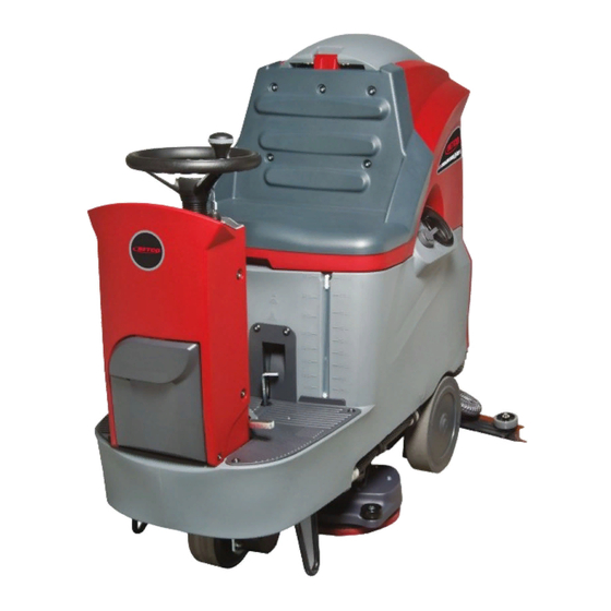
STEALTH
RIDER SERIES
Customer Service: 888-GO-BETCO • Fax: 800-445-5056 • Technical Service: 877-856-5954 • www.betco.com
w/Wet Batteries
w/AGM Batteries
w/Wet Batteries
w/AGM Batteries
DRS
™
1001 Brown Avenue • Toledo, Ohio 43607-0127
26" and 32"
Automatic Rider
Scrubbers
Operator Manual
1
Advertisement
Table of Contents

Subscribe to Our Youtube Channel
Related Manuals for BETCO E29926-00


Summary of Contents for BETCO E29926-00
- Page 1 E29931-00 - 32” w/Wet Batteries E29932-00 - 32” w/AGM Batteries STEALTH 26” and 32” ™ Automatic Rider RIDER SERIES Scrubbers Operator Manual 1001 Brown Avenue • Toledo, Ohio 43607-0127 Customer Service: 888-GO-BETCO • Fax: 800-445-5056 • Technical Service: 877-856-5954 • www.betco.com...
-
Page 2: Table Of Contents
TABLE OF CONTENTS RECEIVING THE MACHINE..........3 TECHNICAL SPECIFICATIONS ........4 GENERAL SAFETY REGULATIONS ......... 5 MACHINE PREPARATION ........6 - 14 OPERATION ..............15 AT END OF WORK ............16 DAILY MAINTENANCE ...........17 - 19 WEEKLY MAINTENANCE ..........20 IRREGULAR MAINTENANCE ........21 TROUBLESHOOTING ..........22 - 23 CHOOSING AND USING THE BRUSHES....... -
Page 3: Receiving The Machine
RECEIVING THE MACHINE Immediately check, when receiving the machine, that all the materials indicated on delivery documents have been received and also that the machine has not been damaged in transit. If it has been damaged, this damage must be immediately reported to the shipper and also to our customer service department. -
Page 4: Technical Specifications
TECHNICAL DESCRIPTION Measurement Unit Stealth DRS26 / 32BT ™ Working width In (cm) 26 (65) / 32 (80) Rear squeegee width In (cm) 37 (94) / 44 (110) Work capacity ft2/h 42,000 / 55,000 Water consumption g/hr Brush & Pad (diameter) in (cm) 13 (32.5) / 16 (40) Brush RPM... -
Page 5: General Safety Regulations
• Before using the machine make sure that all doors and covers are positioned as shown in this operating and maintenance manual. • When your BETCO machine is ready to be retired, the machine must be disposed of properly. It contain oils and electronic components. The machine was built using totally recyclable materials. -
Page 6: Machine Preparation
MACHINE PREPARATION 1. HANDLING THE PACKED MACHINE The machine is contained in specific packaging with a pallet for handling with fork trucks. The packages cannot be placed on top of each other. The dimen- sions of the packaging is as follows: A: 63.25”... - Page 7 MACHINE PREPARATION 3. HOW TO TRANSPORT THE MACHINE • Make sure the recovery tank and solution tank are empty. • Check that the key switch is OFF and remove the key. • Check that the brush deck is lifted off the ground and the squeegee assembly and brushes/pad drivers have been removed from the machine.
- Page 8 MACHINE PREPARATION 7. LEFT SIDE FOOTBOARD COMPONENTS The components on the left side of the footboard are identified as follows: 8. Brake Pedal 9. Parking Brake Lever 8. REAR FOOTBOARD COMPONENTS The components at the rear of the footboard are identified as follows: 10.
- Page 9 MACHINE PREPARATION 11. BATTERY MAINTENANCE AND DISPOSAL For maintenance and recharging, comply with the instructions recommended by the battery manufacturer. Particular attention must be paid when choosing the battery charger, if not supplied with the machine, since there are different kinds according to the type and capacity of the battery.
- Page 10 MACHINE PREPARATION 14. BATTERY DISCHARGE INDICATOR • The battery discharge indicator uses LED’s and has 8 positions, 7 yellow to represent charged batteries, and 1 red to represent batteries that are com- pletely depleted. A few seconds after the red indicator light comes on, the brush motor switches off automatically.
- Page 11 The solution tank has a maximum capacity of 29 gallons. Add Betco liquid detergent to the tank in the concentration and manner indicated on the label.
- Page 12 MACHINE PREPARATION 19. ASSEMBLING THE SQUEEGEE • For packaging reasons, the squeegee is supplied disassembled from the machine and must be installed prior to use. • Make sure the parking brake is engaged and that the key switch is turned to OFF.
- Page 13 MACHINE PREPARATION 22. BRUSH COVER ASSEMBLY The brush cover assemblies will need to be installed prior to using the machine. Make sure the parking brake is engaged and the key switch is turned to OFF. Remove the 8 bolts from the brush deck, there are 4 on each side. Position the brush cover over the deck on the left and right sides of the machine and secure them with the 8 bolts that were previously removed.
- Page 14 MACHINE PREPARATION 25. SERVICING THE MACHINE If problems occur during operation, turn the key switch to OFF, engage the park- ing brake by moving the lever to the left, and disconnect the battery connection to the machine. This will disable all moving parts on the unit. To resume work once the problem has been resolved, reconnect the battery connection to the machine, turn the key switch to ON, and release the parking brake lever.
-
Page 15: Operation
MACHINE OPERATION 28. PREPARING TO WORK 1. Make sure the recovery tank is completely drained. 2. Check that the key switch is in the OFF position. 3. Connect the batteries to the machine (1). 4. Sit on the driver seat. 5. -
Page 16: At End Of Work
AT THE END OF WORK Once completed with work, and before carrying out any type of maintenance, perform the following operations: 1. Close the solution control valve (1) by moving it upward 2. Turn the I-Drive selector to Transport Mode (A), both the squeegee and brush base will rise and after a short time the vacuum motor will turn off. -
Page 17: Daily Maintenance
DAILY MAINTENANCE 30. CLEAN THE RECOVERY TANK 1. Disconnect the drain hose from the clamps and fold over the tube (1) to prevent splashing when the cap is removed. Remove the cap and slowly release tension on the folded area to completely drain the solution tank. WARNING: Always wear gloves when doing this operation to pro- tect yourself from contact with hazardous chemicals. - Page 18 DAILY MAINTENANCE 32. CLEAN THE SQUEEGEE 1. Remove the vacuum hose (1) from the squeegee shoe. 2. Remove the squeegee assembly (2) from the support arm by unscrewing the finger wheels (3). 3. Thoroughly rinse the squeegee blades, squeegee body, and squeegee shoe. 4.
- Page 19 DAILY MAINTENANCE 34. PAD DRIVER/BRUSH REMOVAL 1. Turn the key switch to the ON position 2. Turn the I-Drive selector to the Transport Mode position (A) to lift the brush deck from the floor if it is not already up. 3.
-
Page 20: Weekly Maintenance
WEEKLY MAINTENANCE 35. CLEAN THE VACUUM HOSE If the suction of the squeegee is not adequate, check the vacuum hose for ob- structions. If necessary, clean the hose with a jet of water as described below: 1. Turn the key switch to the ON position. 2. -
Page 21: Irregular Maintenance
IRREGULAR MAINTENANCE 36. REPLACING THE FRONT SQUEEGEE BLADE Suction will be poor and the machine will not dry well if the front squeegee rubber is worn. Proceed to replace as follows: 1. Turn the key switch to the OFF position and remove the key from the control panel. -
Page 22: Troubleshooting
TROUBLESHOOTING GUIDE 39. INSUFFICIENT SOLUTION FLOW 1. Check that there is water in the solution tank (1). 2. Check that the solution flow control valve (3) is pushed all the way down. 3. Clean the solution filter located at the front of the machine. 40. -
Page 23: Choosing And Using The Brushes
TROUBLESHOOTING GUIDE 45. THE MACHINE DOES NOT START 1. Check to ensure the batteries are connected to the machine (1). 2. Check that the key switch is turned on. 3. Check that the batteries are charged (2). 46. ELECTRICAL FUSES AND THERMAL CUT-OFF In addition to standard 80 amp fuses, the machine is also fitted with self-restoring thermal safety fuses located on the electrical boards. -
Page 24: Warranty
Service Distributor. If the original part is returned within the warranty policy period from date of delivery for inspection by Betco and is found to be defective the owner will be credited for the cost of replacement parts plus shipping and handling.
Need help?
Do you have a question about the E29926-00 and is the answer not in the manual?
Questions and answers