Table of Contents
Advertisement
Advertisement
Table of Contents

Subscribe to Our Youtube Channel
Related Manuals for Nortec SAM-e

Summary of Contents for Nortec SAM-e
- Page 1 Your guide to selecting and specifying Nortec SAM-e Short Absorption Manifolds! SAM-e Engineering Manual Includes technical specifications, guidelines, and options for selection and application of SAM-e and Mini SAM-e Short Absorption Manifolds 1503529-F | 22 JUNE 2015...
- Page 2 All references to the Nortec name should be taken as referring to NORTEC. Liability Notice Nortec does not accept any liability for installations of humidity equipment installed by unqualified personnel or the use of parts/components/equipment that are not authorized or approved by Nortec. Copyright Notice...
-
Page 3: Table Of Contents
Static Air Pressure Condensate Losses Correct Choice of Product Applications 15 Product Selection Step 1 Header Selection Step 2 Steam Tube Selection Step 3 SAM-e Steam Inlet Configuration Selection 30 Select Options 35 Installation Drawings 45 Specification 51 Appendix Inlet Adapter Configurations... -
Page 4: Features
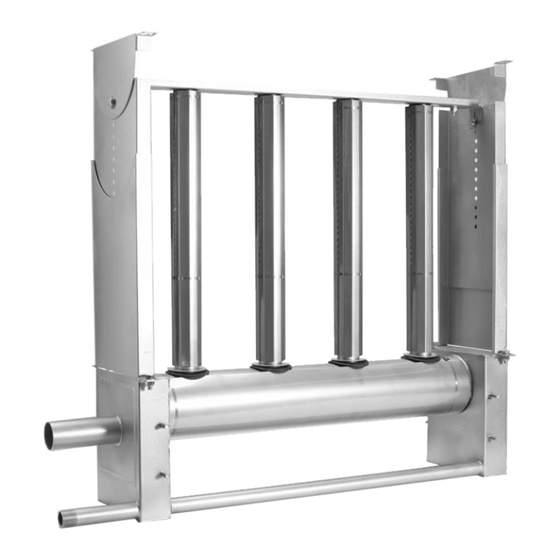
Nortec Short Absorption Manifold (SAM-e) The SAM-e is Nortec‟s best performing steam absorption system for use in Air Handling Units and duct systems where short steam absorption distance is critical. Precisely controlled clean steam is distributed uniformly into the air stream by the SAM-e without any condensate spray. - Page 5 Figure 1: SAM-e Figure 2: Cross-section of distributor pipe SAM-e Engineering | 2...
-
Page 6: Determining The Steam Absorption Distance
Shorter absorption is not always desirable. Sizing a SAM-e to produce unnecessarily short absorption distances may result in increased condensate losses and require a larger humidifier to compensate. It is important to balance available absorption distance with SAM-e capacity. -
Page 7: Static Air Pressure
0.01 (0.3) Condensate Losses Some of the steam generated by NORTEC humidifiers will condense due to SAM-e. To compensate for this loss in capacity, calculated humidification load must be increased accordingly. Please refer to Table 2. Nortec recommends the installation of a condensate drain on the steam-line run prior to entering the SAM-e. -
Page 8: Correct Choice Of Product
The SAM-e is available with optional stainless steel insulation for headers and tubes. Insulation is desirable to reduce air-stream heat gain, reduce condensate losses, and improve energy efficiency. Please refer to Table 3 when estimating condensate losses with insulated SAM-e‟s. -
Page 9: General
Figure 3: General SAM-e Dimensions SAM-e Engineering | 6... - Page 10 Table 4: SAM-e Dimensions – Width Dimension Dimension Dimension Duct Width Frame Width - Bottom Frame Width - Top Header Assembly Width 13.1 14.9 16.3 19.1 20.9 22.3 25.1 26.9 28.3 31.1 32.9 34.3 1067 37.1 38.9 40.3 1219 43.1 1095 44.9...
- Page 11 Table 5: SAM-e Dimensions – Height Dimension Dimension Min. Dimension Max. Duct Height Steam Tube Height Minimum Overall Height Maximum Overall Height 24.7 11.5 30.7 17.5 36.7 23.5 42.7 1084 1067 29.5 1041 48.7 1236 1219 35.5 1194 54.7 1389 1372 41.5...
- Page 12 Figure 4: General Mini SAM-e Dimensions 9 | SAM-e Engineering...
- Page 13 Table 6: Mini SAM-e Dimensions – Width Dimension Duct Width Mini SAM-e Width 11.1 17.1 23.1 Table 7: Mini SAM-e Dimensions – Height Dimension Dimension Duct Height Mini SAM-e Height Mini Steam Tube Height 11.9 13.9 10.4 15.9 12.4 17.9 14.4...
-
Page 14: Product Selection
Product Selection 11 | SAM-e Engineering... -
Page 15: Step 1 Header Selection
There are four options: 3” (76 mm) or 6” (152 mm) or 9” (229 mm) or 12” (305 mm). Mini SAM-e‟s are only available with 3” and 6” spacing. The smaller the spacing, the more tubes the header can accommodate, thus giving a better absorption distance and greater capacity, but at the cost of higher condensate losses. - Page 16 Figure 5: Header / Separator Assembly Figure 6: SAM-e Stand 13 | SAM-e Engineering...
- Page 17 Table 9: SAM-e Header / Separator Assembly, Atmospheric Steam – 3” Centers ATMOSPHERIC STEAM – 3” HEADERS Maximum Capacity Atmospheric Steam [ lb/hr (kg/hr) ] Duct Width Steam Header [ in (mm) ] Tube Qty Part Number Type A Type B...
- Page 18 Table 10: SAM-e Header / Separator Assembly, Pressure Steam – 3” Centers PRESSURE STEAM – 3” Headers Maximum Capacity Pressure Steam [ lb/hr (kg/hr) ] Duct Width Steam Tube Header [ in (mm) ] Part Number Type A Type B...
- Page 19 Table 11: SAM-e Header / Separator Assembly, Atmospheric Steam – 6” Centers ATMOSPHERIC STEAM – 6” HEADERS Maximum Capacity Atmospheric Steam [ lb/hr (kg/hr) ] Duct Width Steam Header [ in (mm) ] Tube Qty Part Number Type A Type B...
- Page 20 Table 12: SAM-e Header / Separator Assembly, Pressure Steam – 6” Centers PRESSURE STEAM – 6” Headers Maximum Capacity Pressure Steam [ lb/hr (kg/hr) ] Duct Width Steam Tube Header [ in (mm) ] Part Number Type A Type B...
- Page 21 Table 13: SAM-e Header / Separator Assembly, Atmospheric Steam – 9” Centers ATMOSPHERIC STEAM – 9” HEADERS Maximum Capacity Atmospheric Steam [ lb/hr (kg/hr) ] Duct Width Steam Header [ in (mm) ] Tube Qty Part Number Type A Type B...
- Page 22 Table 15: SAM-e Header / Separator Assembly, Atmospheric Steam – 12” Centers ATMOSPHERIC STEAM – 12” HEADERS Maximum Capacity Atmospheric Steam [ lb/hr (kg/hr) ] Duct Width Steam Header [ in (mm) ] Tube Qty Part Number Type A Type B...
-
Page 23: Step 2 Steam Tube Selection
18” (457 mm) and 144” (3658 mm). For smaller duct applications, a Mini SAM-e accommodate sizes from 12” (305 mm) wide x 8” (203 mm) high. Nozzles draw hot, dry steam from the center of the tube, eliminating the need for jacket-heating or a temperature switch. Condensate drains vertically down the tube walls into the header, where it is removed through the condensate drain port. - Page 24 1503454 107.5 (2731) 114 (2896) 1503406 1503428 1509407 1503455 113.5 (2883) 1503472 120 (3048) 1503407 1503429 1509408 1503456 119.5 (3035) 126 (3200) 1503408 1503430 1509409 1503457 125.5 (3188) 132 (3353) 1503409 1503431 1509410 1503458 131.5 (3340) 21 | SAM-e Engineering...
- Page 25 2533996 107.5 (2731) 114 (2896) 2533953 2533978 2534026 2533997 113.5 (2883) 1503472 120 (3048) 2533954 2533979 2534027 2533998 119.5 (3035) 126 (3200) 2533955 2533980 2534028 2533999 125.5 (3188) 132 (3353) 2533956 2533981 2534029 2534000 131.5 (3340) SAM-e Engineering | 22...
-
Page 26: Step 3 Sam-E Steam Inlet Configuration Selection
1200 1509089/ 2526056/ 2526057 3" to 1-3/4" 1509087/ 2526052/ 2526053 4” to 3” 1509088/ 2526054/ 2526055 Note: For more options, refer to SAM-e Submittal Drawings, Form #XX-248. Refer to Appendix 1 Adapter Configurations for more information. 23 | SAM-e Engineering... - Page 27 Mini SAM-e Table 22: Mini SAM-e Headers / Separator Assembly – 3” Centers Max. Capacity Atmospheric or Pressurized Steam Duct Width Steam Header [ lb/hr (kg/hr) ] Inlet [ in (mm) ] Tube Qty Part Number 12 (305) 0.5” NPT...
- Page 28 Table 23: Mini SAM-e Headers / Separator Assembly – 6” Centers Max. Capacity Atmospheric or Pressurized Steam Duct Width Steam Tube Header [ lb/hr (kg/hr) ] Inlet [ in (mm) ] Part Number 12 (305) 0.5” NPT 2577692 20 (9)
-
Page 29: Select Options
When ordering tube insulation, order in lengths to match selected tubes. For example: Tubes: 11x 1503415 - Steam Tube, SAM-e, 36" Type B, 304SS (48” in-duct height) Corresponding Insulation: 11x 2538849 – Tube Insulation, SAM-e, 36”... - Page 30 Table 26: Mini SAM-e Tube Insulation Corresponding In-duct Height Part Number Description (See Table 12) [ in (mm) ] Tube Insulation, Mini SAM-e 5” 2538866 8 (203) Tube Insulation, Mini SAM-e 7” 2538867 10 (254) Tube Insulation, Mini SAM-e 9”...
- Page 31 When ordering header/separator insulation for the SAM-e, order insulation lengths to match header/separator lengths. For example: Header: 1503316 – Header /Separator SAM-e 60", 6"-centers Insulation: 2538917 – Header/Separator Insulation, SAM-e 60” Table 27: SAM-e Header/Separator Insulation Part Number Description 2538910 Header/Separator Insulation, SAM-e 18"...
- Page 32 When ordering header insulation for the SAM-e with an atmospheric header 801-1200 lb/hr (dual inlet), order insulation lengths to match header lengths. For example: Header: 1503336 - Header/Separator SAM-e 102" Atmospheric, 801-1200 lb/hr, 6"- centers Insulation: 2539696 – Header/Separator Insulation, 801-1200, SAM-e 108"...
- Page 33 SAM-e to the ceiling and floor. When ordering mounting frames, select the frame with a size range that includes the SAM-e tube length (see Table 6 & 7 “Dimension L”). Mounting frames are available in galvanized and 304 stainless steel.
-
Page 34: Installation Drawings
Installation Drawings 31 | SAM-e Engineering... - Page 35 Figure 8: SAM-e Exploded View SAM-e Engineering | 32...
- Page 36 Figure 9: SAM-e Insulated Exploded View 33 | SAM-e Engineering...
- Page 37 Figure 10: Mini SAM-e Insulated Exploded View SAM-e Engineering | 34...
- Page 38 Note: The SAM-e header functions as a steam separator, therefore an external steam separator is not required Figure 11: Typical SAM-e Installation for Pressurized Steam Applications Note: The SAM-e header functions as a steam separator, therefore an external steam separator is not required...
- Page 39 Figure 12: Typical SAM-e Installation for Atmospheric Steam Applications SAM-e Engineering | 36...
- Page 40 Figure 13: SAM-e Internal Baffle Plate 37 | SAM-e Engineering...
- Page 41 Figure 14: Typical Mini SAM-e Installation for Pressurized Steam Applications SAM-e Engineering | 38...
- Page 42 Figure 15: Typical Mini SAM-e Installation for Atmospheric Steam Applications 39 | SAM-e Engineering...
-
Page 43: Specification
Specification SAM-e Engineering | 40... - Page 44 NORTEC Short Absorption Manifold (Humidifier Steam Dispersion Panel) - SAM-e Humidifier[s], and Mini Short Absorption Manifold (Humidifier Steam Dispersion Panel) – Mini SAM-e Humidifier[s] as indicated on drawing[s] and as indicated on schedule[s]. Complete and operable humidification system [which meets applicable building codes].
- Page 45 3” (76 mm) OR 6” (152 mm) OR 9” (229 mm) OR 12” (305 mm) vertical tubes (3” (76 mm) OR 6” (152 mm) for Mini SAM-e), as necessary to meet absorption distance requirements, and to reduce condensation losses.
- Page 46 (Patent Pending). Un-insulated headers, or simple foam insulation not accepted. Adjustable mounting frame available for quick and easy installation. (Does not apply for Mini SAM-e). Standard of acceptance: Nortec SAM-e. EXECUTION Examination Examine ducts, air-handling units, and conditions for compliance with requirements for installation tolerances and other conditions affecting performance.
- Page 47 Review data in maintenance manuals. Refer to Division 1 Section “Contract Closeout.” Review data in maintenance manuals. Refer to Division 1 Section “Operation and Maintenance Data.” Schedule training with Owner, through Architect, with at least seven days advance notice. SAM-e Engineering | 44...
-
Page 48: Appendix Inlet Adapter
Appendix Inlet Adapter Configurations Note: For Atmospheric Steam humidifier applications, see table 8 and 13 for Pressure Steam applications 45 | SAM-e Engineering... - Page 49 Figure 1: KIT 7/8 - Header and Adapter Configuration SAM-e Engineering | 46...
- Page 50 Figure 2: Kit 1 - Header and Adapter Configuration 47 | SAM-e Engineering...
- Page 51 Figure 3: KIT 2 - Header and Adapter Configuration SAM-e Engineering | 48...
- Page 52 Figure 4: KIT 3 - Header and Adapter Configuration 49 | SAM-e Engineering...
- Page 53 Figure 5: KIT 4 - Header and Adapter Configuration SAM-e Engineering | 50...
- Page 54 Figure 6: KIT 5 - Header and Adapter Configuration 51 | SAM-e Engineering...
- Page 55 Figure 7: KIT 5 - Header and Adapter Configuration SAM-e Engineering | 52...
- Page 56 Figure 8: KIT 5 - Header and Adapter Configuration 53 | SAM-e Engineering...
- Page 57 Figure 9: KIT 6 - Header and Adapter Configuration SAM-e Engineering | 54...
- Page 58 Figure 10: KIT 6 - Header and Adapter Configuration 55 | SAM-e Engineering...
- Page 59 Figure 11: KIT 6 - Header and Adapter Configuration SAM-e Engineering | 56...
- Page 60 Figure 12: KIT 7 - Header and Adapter Configuration 57 | SAM-e Engineering...
- Page 61 Figure 13: KIT 7 - Header and Adapter Configuration SAM-e Engineering | 58...
- Page 62 Figure 14: KIT 7 - Header and Adapter Configuration 59 | SAM-e Engineering...
- Page 63 Figure 15: KIT 8 - Header and Adapter Configuration SAM-e Engineering | 60...
- Page 64 Figure 16: KIT 8 - Header and Adapter Configuration 61 | SAM-e Engineering...
- Page 65 Figure 17: KIT 8 - Header and Adapter Configuration SAM-e Engineering | 62...
- Page 66 Figure 18: KIT 23 - Header and Adapter Configuration 63 | SAM-e Engineering...
- Page 67 Figure 19: KIT 24 - Header and Adapter Configuration SAM-e Engineering | 64...
- Page 68 Figure 20: KIT 25 - Header and Adapter Configuration 65 | SAM-e Engineering...
- Page 69 Figure 21: KIT 25 - Header and Adapter Configuration SAM-e Engineering | 66...
- Page 70 Figure 22: KIT 25 - Header and Adapter Configuration 67 | SAM-e Engineering...
- Page 71 Figure 23: KIT 26 - Header and Adapter Configuration SAM-e Engineering | 68...
- Page 72 Figure 24: KIT 26 - Header and Adapter Configuration 69 | SAM-e Engineering...
- Page 73 Figure 25: KIT 26 - Header and Adapter Configuration SAM-e Engineering | 70...
- Page 74 Figure 26: KIT 27 - Header and Adapter Configuration 71 | SAM-e Engineering...
- Page 75 Figure 27: KIT 27 - Header and Adapter Configuration SAM-e Engineering | 72...
- Page 76 Figure 28: KIT 28 - Header and Adapter Configuration 73 | SAM-e Engineering...
- Page 77 Figure 29: KIT 29 - Header and Adapter Configuration SAM-e Engineering | 74...
- Page 78 Figure 30: KIT 30 - Header and Adapter Configuration 75 | SAM-e Engineering...
- Page 79 Figure 31: KIT 30 - Header and Adapter Configuration SAM-e Engineering | 76...
- Page 80 Figure 32: KIT 30 - Header and Adapter Configuration 77 | SAM-e Engineering...
- Page 81 Figure 33: 0.5” NPT Mini Header and Inlet Configuration SAM-e Engineering | 78...
- Page 82 Figure 34: 0.75” NPT Mini Header and Inlet Configuration 79 | SAM-e Engineering...
- Page 83 Figure 35: 1” NPT Mini Header and Inlet Configuration SAM-e Engineering | 80...
- Page 84 Figure 36: 0.875” Mini Header and Inlet Configuration 81 | SAM-e Engineering...
- Page 85 Figure 37: 1.75” Mini Header and Inlet Configuration SAM-e Engineering | 82...
- Page 86 Figure 38: 3” Mini Header and Inlet Configuration 83 | SAM-e Engineering...
- Page 87 Warranty NORTEC Humidity Inc. and/or NORTEC Humidity Ltd. (hereinafter collectively referred to as THE COMPANY), warrant for a period of ten years after installation, that THE COMPANY‟s manufactured and assembled products, not otherwise expressly warranted (with the exception of the tube coupling seals, two years only), are free from defects in material and workmanship.
- Page 88 U.S.A. 2700 90th Street, Sturtevant, WI 53177 835 Commerce Park Drive, Ogdensburg, NY 13669-2209 CANADA 2740 Fenton Road Ottawa, Ontario K1T 3T7 TEL: 1.866.NORTEC1 EMAIL: nortec@humidity.com WEBSITE: www.humidity.com...
Need help?
Do you have a question about the SAM-e and is the answer not in the manual?
Questions and answers