Table of Contents
Advertisement
Quick Links
Advertisement
Table of Contents

Related Manuals for Grasslin thermio essential BCP


Summary of Contents for Grasslin thermio essential BCP
- Page 1 Operating manual thermio™ essential BCP...
- Page 2 This manual ensures safe and efficient use of the "thermio™ essential BCP" contact thermostat (referred to as “device” in the following). This manual is a component of the device and must remain accessible at all times for everyone who uses the device. Everyone who uses the device must have read and understood this manual before commencing any work.
- Page 3 © Grässlin GmbH Bundesstr. 36 78112 St. Georgen GERMANY Declaration of conformity and download instructions The declaration of conformity for the device described in this manual, and a download of this manual, www.graesslin.de . can be found at...
-
Page 4: Table Of Contents
Overview....................5 Design and function......................5 Contents..........................7 Safety..................... 8 Installation.................... 12 Connecting the electricity....................12 Installation on a pipe......................18 Installation on a cylinder..................... 20 Operation..................... 25 Disposal....................27 Technical data..................29 α λ Ω... -
Page 5: Overview
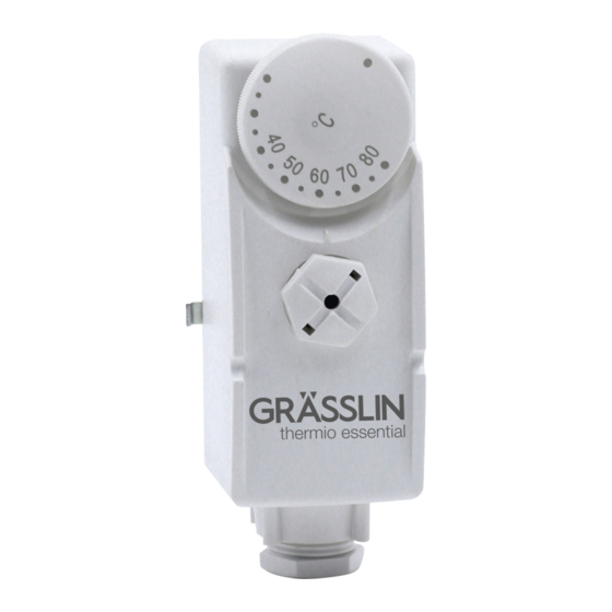
Overview Design and function Design Fig. 1: Front and side view... - Page 6 Cylinder/pipe contact Temperature adjustment knob for temperature setpoint Clearly marked dial Indicator marker Cover retaining screw Cable gland Description of function The "thermio™ essential BCP" contact thermostat is a thermostat that is used to regulate the water temperature, and which is fastened to the cylinder or to a pipe. The current water temperature is meas- ured directly on the surface of the cylinder or the pipe by means of a contact (Fig.
-
Page 7: Contents
Contents The following components are included in the contents: Number Designation Thermio™ essential BCP contact thermostat Spring wire (24 cm) for fastening to a pipe Plastic sheathed wire bracket (1.5 m) with hook for fastening to a cylinder... -
Page 8: Safety
Safety Safety instructions Safety instructions are indicated in this manual by symbols. The safety instructions are introduced by signal words that express the extent of the danger. This combination of symbol and signal word indicates a potentially dangerous situation that may result in death or severe injuries if the situation is not avoided. - Page 9 This combination of symbol and signal word indicates potential dangers for the environment. ENVIRONMENT! Tips and recommendations This symbol highlights useful tips and recommendations, as well as informa- tion for efficient and fault-free operation. Intended use • The contact thermostat may only be used for regulating the temperature of heating systems with a temperature range from 0 °C to +110 °C.
- Page 10 The intended use also includes compliance with all information specified in this manual. Any use other than the intended use or any other type of use are considered incorrect use. The legal warranty is voided by any interference with, or modifications to, the device. Danger due to insufficient wire cross-section! If wires with an insufficient cross-section are used, a short circuit or fire may occur.
- Page 11 Danger to life due to electric shock! Improper assembly and installation of the device can lead to life-threatening electrical voltages. WARNING! − Have assembly and connection performed by a qualified electrician only. Personnel requirements Qualified electrician Professional training, knowledge and experience, and knowledge of the relevant standards and regula- tions allows the qualified electrician to perform work on electrical systems and to identify, and avoid, potential dangers of their own accord.
-
Page 12: Installation
Installation Connecting the electricity Danger to life due to electric shock! Improper assembly and installation of the device may result in life-threat- ening electrical voltages. WARNING! − Have assembly and connection performed by a qualified electrician only. Personnel: • Qualified electrician Special tool: •... - Page 13 The terminals for the flexible wires must have a cross-section between 1 mm² and 2.5 mm². Removing the housing cover Unscrew the cover retaining screw on the housing cover (Fig. 1/5) by hand. Remove the temperature adjustment knob (Fig. 1/2) by pulling it upwards.
- Page 14 Remove the housing cover. Fig. 2: Front view without housing cover...
- Page 15 Terminal 1 Terminal 2 Terminal C Earth contact Cable gland ð The device terminals are visible (Fig. 2). Connecting Strip insulation from the connection wires. • Length of stripped insulation: 8 mm Thread the connection wires into the device through the cable gland (Fig. 2/5).
- Page 16 Fig. 3: Circuit diagram Input contact Contact for temperature decrease Contact for temperature increase To ensure wiring is correct, also consult the operating manual for the heating system in use. Insert the connection wires into the corresponding terminal in accordance with the circuit diagram (Fig.
- Page 17 Insert the earth connection wire into the earth contact (Fig. 2/4). Tightening torques To avoid damage and faulty contacts, tighten the terminals using a torque of 0.6 Nm. NOTICE! Tighten all terminals using the Phillips screwdriver. Installing the housing cover Place the housing cover on the device.
-
Page 18: Installation On A Pipe
Installation on a pipe Personnel: • Qualified electrician Materials: • Thermal compound • Spring wire (24 cm) Prerequisite: The device now has an electrical connection. - Page 19 Ä Chapter "Connecting the electricity" on page 12 Fig. 4: Installation on a pipe Apply thermal compound to the cylinder/pipe contact (Fig. 4/2). Put the device (Fig. 4/3) together with the cylinder/pipe contact onto the pipe (Fig. 4/1) and hook the spring wire into the left-hand hook (Fig.
-
Page 20: Installation On A Cylinder
Ensure that the spring wire has been clamped around the pipe horizontally and that the device is installed level and securely. Installation of the device is now complete. ð Installation on a cylinder Personnel: • Qualified electrician Materials: • Thermal compound •... - Page 21 Ä Chapter "Connecting the electricity" on page 12 Fig. 5: Position on the cylinder Position the device (Fig. 5/2) on the cylinder at a height that is equivalent to around ¼ to ⅓ of the overall height above the floor (Fig. 5/1).
- Page 22 Fig. 6: Dimensions of hole in the insulation Cut a hole in the insulation on the cylinder (Fig. 6, figures in mm).
- Page 23 Fig. 7: Installation on a cylinder Cylinder Hook Cylinder/pipe contact Fastening slot Apply thermal compound to the cylinder/pipe contact (Fig. 7/3).
- Page 24 Clamp the plastic sheathed wire bracket around the cylinder (Fig. 7/1) and hook it into place using the hook (Fig. 7/2). Put the device together with the cylinder/pipe contact onto the cylinder and pull the plastic sheathed wire bracket into the fastening slot (Fig. 7/4) from above. Ensure that the plastic sheathed wire bracket has been clamped around the pipe horizontally and that the device is installed level and securely.
-
Page 25: Operation
Operation Setting the temperature setpoint Personnel: • User Fig. 8: Operation... - Page 26 Temperature adjustment knob for temperature setpoint Clearly marked dial Indicator marker Turn the temperature adjustment knob (Fig. 8/1) so that the indicator marker (Fig. 8/3) points to the temperature setpoint on the clearly marked dial (Fig. 8/2). ð The device activates the heating system and the water temperature is adjusted to the tem- perature setpoint.
-
Page 27: Disposal
Disposal Improper disposal Incorrect disposal presents an environmental danger. Incorrect disposal could result in environmental dangers. − Electric scrap and electronic components must be disposed of correctly, ENVIRONMENT! i.e. the parts for disposal must be sorted into material groups. − Batteries/rechargeable batteries (Directive 2006/66/EC) and electrical or electronic scrap must under no circumstances be disposed of with gen- eral waste. - Page 28 Recycling If no agreement has been made covering return or disposal, ensure that the dismantled components are recycled: • Scrap metals. • Ensure plastic elements are recycled. • Dispose of other components after sorting them according to material properties.
-
Page 29: Technical Data
α λ Ω Technical data Electrical data Voltage level 230 V AC Voltage tolerances ±10% Frequency 50 – 60 Hz Protection class IP40 Rated surge voltage 4 kW Hysteresis ±10 K Control range 0 – +80 °C Temperature sensor range 0 –... -
Page 30: Ambient Conditions
α λ Ω Electrical data Control accuracy ±5 K Mode of operation and additional properties (in Type 1.B accordance with EN 60730-1) Ambient conditions Humidity (in operation) 10% – 90% relative humidity, condensation-free Temperature (in operation) 0 – +55 °C Temperature (storage) –20 –... - Page 31 α λ Ω General data Colour White Weight 159 g Material ABS UL94 V0 Height 105 mm Width 53 mm Depth 38 mm...
- Page 32 Grässlin GmbH Bundesstrasse 36 78112 St. Georgen GERMANY Telephone: +49 7724 933-0 Fax: +49 7724 933-240 info@graesslin.de www.graesslin.de 80.10.1470.7/0217/V01...
Need help?
Do you have a question about the thermio essential BCP and is the answer not in the manual?
Questions and answers