Table of Contents
Advertisement
Advertisement
Table of Contents

Related Manuals for Komfovent VERSO-S


Summary of Contents for Komfovent VERSO-S
- Page 1 VERSO S / R / P / RHP / PCF Installation and Maintenance Service Manual...
-
Page 3: Table Of Contents
2.5. Air Filters and Filter Change Procedure....................19 2.6. Water Air Heaters, Air Coolers, Direct Evaporation Air Coolers .............. 20 2.7. Electric Air Heaters in VERSO-S Series Air Handling Units ..............24 2.8. Electric Air Heaters in VERSO-P/PCF and VERSO-R/RHP Series Air Handling Units ......24 2.9. - Page 4 6.7.2. Outdoor compensated ventilation ....................40 6.7.3. Minimum temperature control ....................... 40 6.7.4. Override function .......................... 40 6.7.5. Summer night cooling ........................41 6.7.6. Operation on demand ........................41 6.7.7. Recirculation control ........................42 6.7.8. Humidity control ..........................42 6.8. Unit operation scheduling ........................43 6.8.1.
-
Page 5: Verso Air Handling Units
1. VERSO AIR HANDLING UNITS UAB Amalva thanks you for choosing VERSO air hadling unit. Because a lot of attention is given towards unit quality we will be thankful for your help expressing your comments and responses, or suggestions regarding technical and running qualities of the unit. -
Page 6: Verso Air Handling Units Marking
1.1. VERSO Air Handling Units marking VERSO Air Handling Units marking: warning Note! Caution! Important information in the Rotating parts! instruction manual. Note! Place for siphon. Before performing any inspection work inside the unit, be sure the unit‘s electric power supply is disconnected. -
Page 7: Verso-S - Air Supply Units
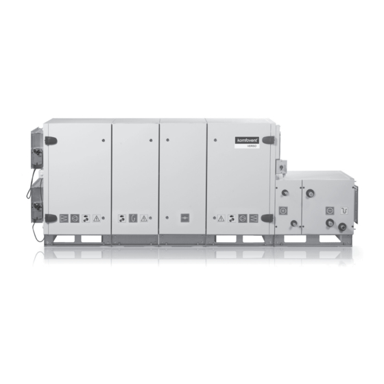
1.2. VERSO-S – Air Supply Units 1. Air damper (closing) 7. Base frame 2. Supply air filters 8. Sections connection 3. Fan with electric motor 9. Sealing gasket 4. Air heater (water or electric) 10. Connection bolt 5. Air cooler (water or direct evaporation) 11. -
Page 8: Verso-R/Rhp - Air Handling Units Equipped With Rotary Heat Exchanger
Under conditions, when the outdoor air temperature is low and humidity is high, risk of heat exchanger frost- ing may appear. For this reason anti-frost protection function is foreseen in the controller of the Komfovent air handling units. Depending on the type of the recovery, different methods of anti-frost protection are available: cold air by-passing, or / and supply air fan speed reducing. -
Page 9: Verso Air Handling Units Composing Options
1.6. VERSO Air Handling Units Composing Options VERSO-S VERSO-P/PCF VERSO-R/RHP outdoor intake supply air extract indoor exhaust air IS-1 Air handling unit inspection doors on the right; supplied airflow into room is on the bottom of the unit. IS-2 Air handling unit inspection doors on the left; supplied airflow into room is on the bottom of the unit. -
Page 10: Verso Air Handling Units Construction
2. VERSO AIR HANDLING UNITS CONSTRUCTION 2.1. Fans VERSO air handling units are equipped with radial fans with direct drive. Motors of the fans with backward curved blades must be controlled by frequency converters. Frequency set by the frequency inverter cannot exceed frequency data specified in the print out. - Page 11 1. Plate heat exchanger 2. Support frame 3. Frame 4. Bottom shields 5. Place of sections connection 6. Bypass damper with actuator 7. Drop eliminator (if needed) 8. Condensate bath with drainage Plate heat exchanger can be easily removed for inspection. Removing plate heat exchanger from VERSO-P/PCF air handling units.
-
Page 12: Rotary Heat Exchanger In Verso-R/Rhp Air Handling Units
2.3. Rotary Heat Exchanger in VERSO-R/RHP Air Handling Units The heat exchanger actuator mechanism is oiled with synthetic solution; therefore there is no need to oil mechanism during its exploitation. It is important to make sure that the rotary heat exchanger mechanism is clean: to change the filters installed in the air handling unit on time, to perform periodical heat exchanger cleaning. - Page 13 VERSO-RHP functional schemes One circuit system 1. Compressor 9. Solenoid valve 2. 4-way valve 10. LP tranducer 3. Check valve 11. HP tranducer 4. Liquid receiver 12. Temperature tranducer 5. Rotalock valve 13. Supply air coil 6. Filter – drier 14.
- Page 14 Two circuit system VERSO-RHP 60, 70, 80, 90 1. Compressor 2. 4-way valve 3. Check valve 4. Liquid receiver 5. Rotalock valve 6. Filter – drier 7. Moisture indicator 8. Electronic expansion valve 9. Thermostatic expansion valve 10. Solenoid valve 11.
- Page 15 VERSO-RHp unit data Number of circuits Compressors quantity in one circuit Refrigerant quantity in 1 circuit, kg Refrigerant quantity in 2 circuit, kg Informative sticker inside the unit UAB AMALVA we reserve the right to make changes without prior notice V2-C5-15-03-v1...
- Page 16 Troubleshooting of heat pump Possible solution Possible solution Message Probable cause in heating mode in cooling mode Compressor motor, drive or control system See operation manual (p. 94). failure. Compressor failure The compressor has operated in critical conditions or there is insuf- Overload protection ficient refrigerant amount in heat pump hydraulic circuit.
- Page 17 Possible solution Possible solution Message Probable cause in heating mode in cooling mode Low air flow. Increase supply and (or) extracted air flow. Low level of refrigerant. See C8. Heat pump works regulary but with an 4-way valve failure. Check 4-way valve coil. Check 4-way valve and replace if necessary. insufficient capacity Defrost solenoid valve Check solenoid valve coil.
- Page 18 EHA – exhaust air ETA – extract indoor SOA – outdoor intake SA – supply air RCA – recirculated air Using Verso RHP devices with recirculation section the supply air temperature sometimes can‘t be supported. For this it is recommended to choose an additional heater / cooler to ensure the supply air temperature. Otherwise, the supply air temperature will not reach set point.
-
Page 19: Air Dampers
2.4. Air Dampers Closing air dampers with aluminium or galvanized steel blades are used in the units. Air damper is fixed to the air handling unit with screws. 1. Aluminum or galvanized steel blades 2. Rubber sealing 3. Plate shaft for the actuator 4. -
Page 20: Water Air Heaters, Air Coolers, Direct Evaporation Air Coolers
4. Two-step direct evaporation air cooler Water Air Heaters, Air Coolers, Direct Evaporation Air Coolers in VERSO-S Units Possible VERSO-S composition options: with the air heater and air cooler and additional heater mounted outside the unit. UAB AMALVA we reserve the right to make changes without prior notice... - Page 21 Water Air Heaters, Air Coolers, Direct Evaporation Air Coolers Mounted at the Bottom of VERSO-P/PCF, VERSO-R/RHP Units The section of air heater, air cooler, or direct evaporation air cooler insulated in mineral wool is mounted on the outside of the unit. Therefore air handling unit takes less space and it is more convenient to install. 1.
- Page 22 Water Air Heater, Air Cooler, Direct Evaporation Air Cooler Connection to VERSO-P/PCF and VERSO-R/RHP Series Air Handling Units When connecting heat exchanger to the system, it is necessary to use two pipe wrenches: Be careful when exploitating hot water air heaters as the heating agent temperature may reach 130 °C! When operating air handling unit in the temperatures lower than 0 °C, it is necessary to use glycol additionally or assure the reversible heating agent...
- Page 23 VERSO sections connection using clamping elements View B View C View A The sections clamping elements are supplied to the device. They are used in the front and back of the unit in the upper part of the section. Sections are tightened with screws in the frame holes (image A). Tightening the two equal in height single-flow sections clamping elements are located on the top of section, and if allows unit con- struction, on the sides of the section (image B).
-
Page 24: Electric Air Heaters In Verso-S Series Air Handling Units
2.7. Electric Air Heaters in VERSO-S Series Air Handling Units Three interconnected unit parts are bolted together. When heating capacity exceeds 45 kW, additional electric heater section may be used (also up to 45 kW). In such a case additional heater is con- nected to the supply air vent (after the ventilation section). - Page 25 1. Sealant 2. Unit main-switch 3. Heater main-switch 4. Linkage connecting the heater and the unit Electric Air Heaters Protection from Overheating Three safety measures protect electric air heaters from overheating. 1. 70 °C heater overheating protection. When airflow velocity is too low, it does not allow the heater elements to get hotter more than 200 °C.
-
Page 26: Verso Series Air Handling Units Designed For The Outdoor Use
2.9. VERSO Series Air Handling Units Designed for the Outdoor Use VERSO air handling units, which are designed for outdoor use, can be additionally assembled with roofs with water drain tray to opposite viewing side. Every section has separate roof which must only be connected together. 1. -
Page 27: Verso Air Handling Units Transportation
3. VERSO AIR HANDLING UNITS TRANSPORTATION VERSO Air Handling Units Transportation by Crane, Lift Truck and Carts The unit is transported separately. While transported, each section is fixed to a wooden pallet and wrapped. Dampers and flanges are supplied not fixed to the unit. They are on the top of each unit section. Sealing, connecting and fixing bolts are inside in each section. -
Page 28: Verso Air Handling Units Installation
4. VERSO AIR HANDLING UNITS INSTALLATION 4.1. VERSO Air Handling Units Maintenance Space Maintenance space is needed for convenient inspection of the unit; perform maintenance works; when there is a need to pull it out for inspection, change parts of the unit or even the whole unit. In order to change some unit components, there might be a need to demount the unit partially or completely. -
Page 29: Setting And Installing Verso Air Handling Units
4.2. Setting and Installing VERSO Air Handling Units Before installing air handling unit it is important to remove transportation elements. If the unit was transported not on the positioning frame, sections should be placed from wooden panels to positioning frame. The unit is installed on even and solid base, location that was assigned to it. -
Page 30: Connection To The Air Duct
4.3. Connection to the air duct VERSO Air Handling Unit is connected to the Air Duct in Two Ways Air ducts are connected to VERSO units through L-20 connectors. VERSO units of size 60, 70, 80,90, are connected through L-30. Air damper connection to the air duct 1. -
Page 31: Check-Up Before Turning On Verso Air Handling Unit
Any drainage systems must not be connected directly to the municipal sewage system. The condensate tray shall be easily accessible for cleaning and disinfection. Precaution: The drainage siphon should be mounted on the outlet fitting pipe of every drip tray for complete condensate drainage from the air han- dling unit and prevention of penetration of offensive odours from an efflu- ent into the ventilation system. -
Page 32: Electrical Installation Manual
5. ELECTRICAL INSTALLATION MANUAL Installation works may be performed only by duly qualified personnel. The following requirements must be fulfilled during installation. It is recommended to lay control circuit cables separately from power ca- bles or to use shielded cables. In this case, the cable shielding must be grounded! 5.1. - Page 33 Controller with connection terminals 5.3 a Picture 1. Control panel connection 2. „Ethernet“ computer network or internet connection 3. Fuse 1A External control elements connection 5.3 b Picture UAB AMALVA we reserve the right to make changes without prior notice V2-C5-15-03-v1...
-
Page 34: Temperature Sensors Installation
5.4. Temperature Sensors Installation The supply air temperature sensor B1 (5.4 a Picture) is mounted in the air duct in a projected place for it; after electric heater or cooler section (if provided). The minimal distance from the air vent of the unit up to the sensor should be not less than a diagonal of rectangular connection. -
Page 35: Operation Manual
6. OPERATION MANUAL 6.1. Unit control Air handling units control system ensures control of the physical processes that are taking place inside the air handling unit. Control system consists of: • main controller module; • several extension modules; • circuit breakers and main switch; •... -
Page 36: Parameters Review
Main window of the panel 6.3 Picture Light Diode Indication: 1. Constant green light – the unit is on; 2. Flashing red and green light – fault alarm; however, the unit operation is not shut down; 3. Flashing red light only – fault message; the unit operation is shut down. Explanation of the symbols Holliday schedule operation Air damper operation symbol... -
Page 37: Unit Programmable Settings
Main windows of control panel 6.4 Picture Note: The fourth window is shown only when the air quality or humidity function is activated. 6.5. Unit Programmable Settings By touching button in the main window, the parameters setting menu (Picture 6.5) is entered. The menu window is selected with buttons. -
Page 38: Settings Of Unit Modes
6.6. Settings of unit modes 6.6.1. Operation modes Six operation modes of the unit are possible: 1. There is two Comfort and two Economy modes, for each of them the user can set air flow and temperature; 2. Program – in this mode the unit operates according to the preset schedule; 3. -
Page 39: Temperature Control Modes
6.6.3. Temperature control modes The air handling unit provides for several temperature control modes: • Supply. The unit supplies air according to the temperature preset by the user. • Exhaust. Unit automatically supplies air of such temperature to maintain preset exhaust air temperature. •... -
Page 40: Outdoor Compensated Ventilation
Ventilation in- F1 – user-selected air flow (actual) tensity, F2 – minimum air flow 20 % W1 – winter compensation start point W2 – winter compensation end point S1 – summer compensation start point S2 – summer compensation end point The ventilation compensation Outdoor temperature,... -
Page 41: Summer Night Cooling
• Switches off the air handling unit; • Switches over the unit to operation according to the mode “Comfort1”; • Switches over the unit to operation according to the mode “Comfort2”; • Switches over the unit to operation according to the mode “Economy1”; •... -
Page 42: Recirculation Control
Operation on demand (start-up / shut-down) is performed by the same sensor which is used in the control of the “Air quality function”. A room sensor with the analogue output (0...10V DC) should be designed for this function. 6.7.7. Recirculation control The air handling unit with a mixing section has the extract air recirculation function, i. -
Page 43: Unit Operation Scheduling
• Room air. The determined humidity of indoor air is maintained, using the room air or exhaust air duct humidity sensor (B8). The supply air humidity limit is set using the duct humidity sensor or hydrostat (B9). One of the below methods can be chosen for maintenance of the determined humidity: •... -
Page 44: Alarms And Status
6.9. Alarms and status 6.9.1. Actual alarms This menu shows messages on existing faults. Messages are deleted when “Delete” is selected. 6.9.2. Alarm history Former messages are shown here. 6.9.3. Operation counters This menu shows the operation time or energy consumption of the heater and fans. 6.9.4. -
Page 45: Filter Status
6.9.5. Filter status It is possible to monitor the pollution level of filters and to calibrate clean filters. It is recommended to perform the initial calibration of filters after the first start of the unit. When filters are replaced during operation, it is recom- mended to perform the clean filter calibration. -
Page 46: Control Of Air Handling Units Through A Web Browser
6.11. Control of air handling units through a web browser You may not only monitor the operation of VERSO air handling units and the functionality of their individual components, change settings and activate extra functions by means of control panel but also by your computer. All you need is to connect the unit to the computer, local area network or the Internet using a network cable. -
Page 47: Multi-Level Control Of Direct Evaporation Cooler
Combi-coil control function must be ordered in advance. 6.12.2. Multi-level control of direct evaporation cooler For air cooling in the air handling unit there is provided 3 control contacts (connection is shown in Picture 5.3 b). Depending on how much will be cooling steps and how it will be divided on steps, automatically will be selected optimal control method. -
Page 48: Troubleshooting
The purpose of additional zone heater/cooler could be changed from independent to additional control. In such case this control mode can be used when the air handling unit is equipped with several heaters/coolers of the same type, or when the standard configuration of the control system does not provide the required demand. Additional zone control is ordered in advance. - Page 49 Message Possible cause Elimination A fire signal has been received from the fire Delete alarm message and restart the unit when External fire alarm signalization system of the building. the fire signal disappears. A signal from an external device (switch, As soon as the auxiliary device is switched off, the External stop timer, or sensor) has been received.
- Page 50 Message Possible cause Elimination Check the condition of the rotor motor and make Rotor motor overload The rotor motor is overloaded. sure that the rotor is not blocked. No communication with the internal com- ponents of the air handling unit (controller Check internal connections and functioning of Communication error extension modules, frequency converters,...
Need help?
Do you have a question about the VERSO-S and is the answer not in the manual?
Questions and answers