Table of Contents
Advertisement
Contents
Overview . . . . . . . . . . . . . 1
Single Unit . . . . . . . . . . . 3
Front of CPE . . . . . . . . . . 3
Back of CPE . . . . . . . . . . 6
Operating Information. . . 7
Overview . . . . . . . . . . . . . 7
Before You Begin . . . . . . 7
Easy Setup. . . . . . . . . . . . 9
Advanced Setup . . . . . . 10
Configuration . . . . . . . . 11
Logging In to the CPE. . 11
Step 2 - Device Time. . . 14
Step 4 - Account . . . . . . 15
Personalize Menu . . . . . 17
Internet Menu . . . . . . . . 21
Status Menu. . . . . . . . . . 25
Telephony Menu . . . . . . 26
Contents
-1
Advertisement
Table of Contents

Related Manuals for Motorola CPEi 300


Summary of Contents for Motorola CPEi 300
-
Page 1: Table Of Contents
Contents Desktop CPEi 300 User Guide Overview ... . . 1 Powerful Features in a Single Unit ... 3 Front of CPE ..3 Back of CPE . - Page 2 Help ....56 Important Safety and Legal Information Disposal of Motorola Equipment in EU Countries ..62...
-
Page 3: Desktop Cpei 300 User Guide
Desktop CPEi 300 User Guide Overview Thank you for purchasing the Motorola CPE Indoor (CPEi) 300 desktop device. The Desktop CPEi allows you to connect to the wireless world easily and seamlessly without complicated installa- tion and setup procedures. In addition it offers you the ability to make Voice over Internet Protocol (VoIP) calls. - Page 4 The features and the physical appearance of your Desktop CPEi device may differ slightly from the illustration. This product is subject to change. For the most recent documentation, visit the Product Documentation page on www.motorola.com. Desktop CPEi 300 User Guide...
-
Page 5: Powerful Features In A Single Unit
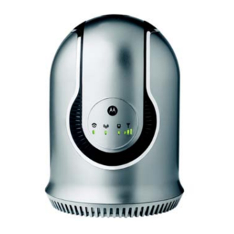
• Home Gateway Functions Front of CPE The Front of the CPE units contain LED Link/Activity indicators. The LEDs provide the status of the unit and signal strength indicators for easy adjustment during setup. Front of Unit Desktop CPEi 300 User Guide... - Page 6 • All WiMAX Signal Strength LEDs are off - low signal detected. • First WiMAX Signal Strength LED is lit - low signal detected. • First and second WiMAX Signal Strength LED is lit - high signal detected. Desktop CPEi 300 User Guide...
- Page 7 LEDs are blinking, then a software upgrade is in progress. Do NOT remove power to the CPE. Note: If the Power LED is BLINKING and all 3 WiMAX Signal Strength LEDs are OFF, the CPE device is overheating, and you will not have service. Desktop CPEi 300 User Guide...
-
Page 8: Back Of Cpe
Before resetting the CPE, ensure the power LED is ON. Phone Line 1 RJ-11 port for use with VoIP. Phone Line 2 RJ-11 port for use with VoIP. Desktop CPEi 300 User Guide... -
Page 9: Operating Information
Operating Information Operating temperature for this unit is 0-40C (32-104F). Installation Overview To install the Desktop CPEi 300 Series, you need to review the following sections: • Before You Begin • Easy Setup Before You Begin Before you begin installation, check that you have received the... - Page 10 In addition, you will also need: • A computer • An RJ-11 telephone cable (optional). Two RJ-11 telephone cables will be required if your service provider has supplied you with two telephone numbers. Desktop CPEi 300 User Guide...
-
Page 11: Easy Setup
Phone line activation is dependent upon your service contract. • Plug the other end of the phone line into the phone line connector of your telephone. Desktop CPEi 300 User Guide... -
Page 12: Advanced Setup
The CPE can also be used to connect to a multi-port switch (hub) - purchased separately from the CPE. Connecting the CPE device to a hub will allow you to connect more than one computer to your CPE device. See the picture below for an example. Desktop CPEi 300 User Guide... -
Page 13: Procedure To Log Into The Cpe
ENTER to display the login screen. Note: You must include the period (.) after http://mywimax. in order to access the login screen. 3 The Welcome to Motorola WiMAX CPE screen will be displayed and will prompt you for a password. Desktop CPEi 300 User Guide... - Page 14 Login Screen In the Password field, type the password (default is motorola). 5 Click Login. 6 First time users will see a pop-up box that states: “The Wizard application will guide you through for the first time configuration. Click OK button to continue.”...
-
Page 15: Setup Wizard And Authentication
• Click Next. Note: If you forget your password, you can reset it back to the default (motorola) by pressing and holding the reset button on the back of your CPE for more than 5 seconds. Before resetting the CPE, ensure the power LED is ON. -
Page 16: Step 2 - Device Time
Step 2 - Device Time This screen allows you to set the time zone and to enable Daylight Savings Time (when applicable) for your location. • Select the appropriate time zone for your location from the drop down box. • Check the box called “Auto Adjust for Daylight Savings Time”... -
Page 17: Step 4 - Account
Step 4 - Account The Account tab will allow you to manage Voice over IP (VoIP) related services. Please consult with your telephony service provider for these settings. Click the Apply button when finished. Congratulations! You have now completed the setup of your WiMAX connection. - Page 18 Status Screen • The Restart button will shut down the CPE device and restore all factory settings. Note: The restart button is available on every screen. • The Wizard button will prompt you to start the set-up wizard over again. •...
-
Page 19: Basic Configuration
Basic Configuration Once the CPE set up has been completed, you can login to your CPE from any computer on your home network by typing the device name in the address bar. The default device name is mywimax. This section describes the PERSONALIZE, INTERNET, and STATUS Menus that are available. - Page 20 Personalize Menu Password Tab The password tab allows you to enable/disable password protection. You can also change your password here. Be sure to click the Apply button when finished. Field or Button Description Checking this box will require login Enable Login password protection.
- Page 21 Device Time Tab The Device Time tab allows you to establish the time zone for your location. It also allows you to automatically adjust for Daylight Savings Time if necessary. Be sure to click the Apply button when finished. Field or Button Description Current Local Shows the current local date and time.
- Page 22 Restore Factory Settings Tab The Restore Factory Settings Tab will reset your CPE to the manufacturers default settings. Be sure to click the Apply button if you are sure you want to reset factory settings. Field or Button Description Checking this box will restore the CPE to Restore Factory factory default settings.
-
Page 23: Internet Menu
Internet Menu The Internet menu provides the following tabs: • WiMAX Security • Internet Protocol • Firewall • Dynamic DNS Internet Menu Basic Configuration... -
Page 24: Wimax Security Tab
WiMAX Security Tab The WiMAX Security tab will contain your authentication method. Check with your service provider to determine if they require a user name and password for authentication purposes. Field or Button Description Authentication Drop down box allows you to select either Method EAP-TLS (default) or EAP-TTLS/MS-CHAPv2. -
Page 25: Firewall Tab
Firewall Tab A firewall helps to protect your home network from unauthorized access. It will also help to manage authorized access from the internet to your CPE. Field or Button Description Enable Firewall Check this box to enable the firewall for your home network. -
Page 26: Dynamic Dns Tab
Dynamic DNS Tab Dynamic Domain Name Service (DDNS) allows a user with a non-static IP address to keep their domain name associated with an ever changing IP address. As an example, DDNS is used when you are hosting your own website. Field or Button Description Enable DDNS... -
Page 27: Status Menu
Status Menu The Status menu provides the following tabs: • Network • Telephony Status Menu Network Tab The Network tab will provide any status associated with your WiMAX Wireless Broadband connection. Telephony Tab The Telephony tab will provide any status associated with yoru telephony connection. -
Page 28: Telephony Menu
Telephony Menu The telephony menu allows you to manage your Voice over Internet Protocol (VoIP) services. Note: Contact your service provider to obtain VoIP service, if you do not already have this service. The Telephony menu provides the following tabs: •... -
Page 29: Account Tab
Account Tab Please consult with your service provider for these settings. Field or Button Description Realm Enter Realm information as provided by your service provider. Line 1 User If Line 1 is an active VoIP, enter the User Name Name as provided by your service provider. Line 1 Password Enter the Line 1 password as provided by your service provider. -
Page 30: Caller Id Tab
Field or Button Description Default Line 1 Use the drop down box to select a ring tone Ring Type for Line 1. The default is ringtone R0. Test Click to hear how the selected ring tone will sound. Default Line 2 Use the drop down box to select a ring tone Ring Type for Line 2. -
Page 31: Call Forwarding Tab
Field or Button Description Enable Line 2 If Line 2 is your active telephone port, check Anonymous this box if you would like to reject telephone Incoming Call calls from anonymous incoming callers. The Rejection default is checked. Enable Line 2 If Line 2 is your active telephone port, check Permanent this box if you would like to permanently... - Page 32 Field or Button Description Line 1 No If “Line 1 No Answer Forwarding to Num- Answer ber” is checked, enter the telephone number Forwarding to you would like to forward calls to when there Number is no answer on Line 1. This function is not available if “Enable Line 1 Basic Forwarding is checked”.
- Page 33 Field or Button Description Line 2 No If “Line 2 No Answer Forwarding to Num- Answer ber” is checked, enter the telephone number Forwarding to you would like to forward calls to when there Number is no answer on Line 2. This function is not available if “Enable Line 2 Basic Forwarding is checked”.
-
Page 34: Voice Mail Tab
Voice Mail Tab The voice mail tab allows you to see the status of your voice mail. Note: Please contact your service provider to activate the voice mail feature if it is not already active. Field or Button Description Line 1 Server Shows the status of Line 1 voice mail as Based Voice Mail either enabled or disabled. - Page 35 The following descriptions are valid for both Line 1 and Line 2. Field or Button Description Service Provider Use this number to contact customer service Contact Number for your service provider. Emergency Dial this number to reach local emergency Number services.
- Page 36 Field or Button Description Call Forwarding Dial this number to change the phone number Busy Change to which calls will be forwarded when the Number line is busy. Call Forwarding Dial this number to forward calls to a differ- No Answer ent number when there is no answer on Line Activate 1 or Line 2.
- Page 37 Field or Button Description Line Blocking Dial this number to unblock your telephone Deactivate number from appearing on Caller ID. Call Waiting Dial this number to toggle between call wait- Toggle ing ON and call waiting OFF. Anonymous Call Dial this number to have anonymous calls Rejection rejected.
-
Page 38: Advanced Configuration
Advanced Configuration The Advanced Configuration section describes the Port Forwarding, Local Address, and Control Panel menus. Port Fowarding Menu Port forwarding enables you to direct incoming traffic to specific LAN hosts (computers on your network) based on the protocol and port number. It is used to play Internet games or provide local services (such as web hosting) for a LAN group. - Page 39 Basic Tab Field or Button Description Enable UPnP Enables Universal Plug and Play (UPnP) Internet Gateway Device (IGD) profile to allow certain Windows applications to setup the port forwarding rule dynamically when NAT is enabled on this device. Enter the DMZ IP Address. (DeMilitarized Zone) IP Address Be sure to click the Apply button once you have made changes.
-
Page 40: Forwarding Tab
Forwarding Tab Click on the ADD button to create additional Port Fowarding rules. Field or Button Description Select Select a box when you want to delete the spe- cific row. Protocol Select TCP (Transmission Control Protocol) or UDP (User Datagram Protocol). WAN Port Start Enter the beginning port range for external network access. -
Page 41: Local Address Menu
Local Address Menu The Local Address menu allows you to configure your Local Area Network (LAN) connections. The Local Address menu provides the following tabs: • DHCP Server • Lease Status • Lease Reservation Local Address Menu Advanced Configuration... -
Page 42: Dhcp Server Tab
DHCP Server Tab The DHCP Server tab enables Dynamic Host Configuration Protocol (DHCP) server functionality on the LAN, allowing the router to dynamically assign lease IP addresses to clients that connect to it from the local network. Field or Button Description Enable DHCP If selected, the DHCP server on the gateway... - Page 43 Field or Button Description DHCP Lease Sets the time, in seconds, that a network Time computer remains connected to the gateway using its current assigned IP address. At the end of this time, the DHCP server renews the lease or assigns the computer a new IP address.
- Page 44 Lease Status Tab The Lease Status tab in the Local Address menu displays the active DHCP leases since the last reboot. Field or Button Description Client Host Displays the client host name. The Name Name field is limited to 20 characters (only 5 appear in display).
-
Page 45: Lease Reservation Tab
Lease Reservation Tab This tab allows you to manage the lease reservation so that the same client receives the same IP address each time. Field or Button Description Select Select this box if you want to delete an estab- lished lease reservation. Be sure to click the Delete button once you have selected your exception to be deleted. -
Page 46: Control Panel
Control Panel The Control Panel sections allows you to view/update your software information. The Control menu provides the following tabs: • Software • Certificate • System • About Control Panel Menu Advanced Configuration... -
Page 47: Software Tab
Software Tab The Software tab manages the software on your CPE device. It is also where you can upgrade device software. Use the BROWSE button to browse your computer for additional software packages. Once you have located the software package/update you would like to add to your device, click on the Upgrade button. -
Page 48: About Tab
System Tab This tab allows you to manage additional features of your CPE device. Field or Button Description Language Used Select the desired language for the user in User Interface interface. The default language is English. Enable WiMAX Check this box to enable the WiMAX Radio Interface Radio Interface. -
Page 49: Configuring Tcp/Ip
Configuring TCP/IP This chapter is needed for setup procedures. All client computers on your network must be configured for TCP/IP (the protocol that controls communication among computers). Perform one of: • Configuring TCP/IP in Windows 2000 • Configuring TCP/IP in Windows XP Note: Follow the instructions in your Macintosh or UNIX user manual Configuring TCP/IP in Windows 2000... - Page 50 Windows Control Panel Double-click the Network and Dial-up Connections icon to display the Network and Dial-up Connections window: Network and Dial-up Connections In the steps that follow, a connection number like 1, 2, 3, etc., is a reference that is displayed on computers with multiple network interfaces.
- Page 51 Click Local Area Connection number. The value of number varies from system to system. The Local Area Connection number Status window is displayed: Local Area Connection Click Properties. Information similar to the following window is displayed: Properties Configuring TCP/IP...
- Page 52 If Internet Protocol (TCP/IP) is in the list of components, TCP/IP is installed. You can skip to Step 10. If Internet Protocol (TCP/IP) is not in the list, click Install. The Select Network Component Type window is displayed: Select Network Connection Type Click Protocol on the Select Network Component Type window and click Add.
-
Page 53: Configuring Tcp/Ip In Windows Xp
Be sure the box next to Internet Protocol (TCP/IP) is checked. 11 Click Properties. The Internet Protocol (TCP/IP) Properties window is displayed: Internet Protocol (TCP/IP) Properties Be sure Obtain IP address automatically and Obtain DNS server address automatically are selected. 13 Click OK to accept the TCP/IP settings. - Page 54 Windows XP Start Window Click Control Panel to display the Control Panel window. The display varies, depending on your Windows XP view options. If the display is a Category view as shown below, continue with Step 3. Otherwise, skip to Step Control Panel Click Network and Internet Connections to display the Network and Internet Connections window:...
- Page 55 Network and Internet Connections Click Network Connections. Skip to Step 6. If a classic view similar to below is displayed, double-click Network Connections to display the LAN or High-speed Internet connections. Control Panel Classic View Right-click the Local Area Connection. If more than one connection is displayed, be sure to select the one for your network interface.
- Page 56 Network Connections Select Properties from the pop-up menu to display the Local Area Connection Properties window: Local Area Connection Properties On the Local Area Connection Properties window, select Internet Protocol (TCP/IP) if it is not selected. Click Properties to display the Internet Protocol (TCP/IP) Properties window: Configuring TCP/IP...
- Page 57 Internet Protocol (TCP/IP) Properties 10 Be sure Obtain IP address automatically and Obtain DNS server address automatically are selected. Click OK to close the TCP/IP Properties window. Configuring TCP/IP...
-
Page 58: Troubleshooting
Troubleshooting Power LED is Off • Check that the AC power adapter is properly plugged into the electrical outlet and into the Desktop CPE. • Check that the electrical outlet is working. A Computer Cannot Log On to the CPE Check that the Ethernet cable is properly connected to the Desktop CPE unit and the computer. -
Page 59: Important Safety And Legal Information
Important Safety and Legal Information Your Motorola WiMAX Wireless Broadband Gateway is designed and tested to comply with a number of national and international standards and guidelines (listed below) regarding human exposure to RF electromagnetic energy. This Product complies with the following RF energy exposure standards and guidelines: •... -
Page 60: Fcc Regulatory Information
Gateway desktop transmitter should be operated at a minimum separation distance of 20 cm from all persons. For additional information on exposure requirements or other training information, visit http://www. motorola.com/rfhealth FCC Regulatory Information This device complies with Part 15 of the FCC Rules. Operation is... -
Page 61: Important Safety And Legal Information
EU Declaration of Conformity Important Safety and Legal Information... - Page 62 Important Safety and Legal Information...
-
Page 63: Important Safety And Legal Information
In compliance with national requirements, a power supply cord with a cross-sectional area of 0.75mm minimum for each individual conductor, will be provided when the product is submitted for national approval. Important Safety and Legal Information... -
Page 64: Disposal Of Motorola Equipment In
Union Restriction of Hazardous Substances (EU RoHS) directive. Please do not dispose of Motorola Networks equipment in landfill sites. In the EU, Motorola Networks in conjunction with a recycling part- ner will ensure that equipment is collected and recycled according to the requirements of EU environmental law. -
Page 65: Disposal Of Motorola Networks Equipment In Non-Eu Countries
Disposal of Motorola Networks Equipment in Non-EU countries In non-EU countries, dispose of Motorola Networks equipment in accordance with national and regional regulations. Important Safety and Legal Information... -
Page 66: Cmm Disclosure
CMM Disclosure The China Management Methods (CMM) Disclosure Table is intended only to communicate compliance with China requirements; it is not intended to communicate compliance with EU RoHS or any other environmental requirements. CMM Disclosure... -
Page 67: Cmm Disclosure
CMM Disclosure Information CMM Disclosure... -
Page 68: Copyrights And Trademarks
However, no responsibility is assumed for inaccuracies or omissions. Motorola, Inc. reserves the right to make changes to any products described herein and reserves the right to revise this document and to make changes from time to time in content hereof with no obligation to notify any person of revisions or changes. -
Page 69: Usage And Disclosure Restrictions
Accordingly, any copyrighted material of Motorola and its licensors contained herein or in the Motorola products described in this instruction manual may not be copied, reproduced, distributed, merged or modified in any manner without the express written permission of Motorola. -
Page 70: Trademarks
High Risk Activities. Trademarks MOTOROLA and the Stylized M Logo are registered in the US Patent & Trademark Office. All other product or service names are the property of their respective owners.