Vermont Castings Defiant 1945 Service Manual
Hide thumbs
Also See for Defiant 1945:
- Homeowner's installation and operating manual (41 pages) ,
- Homeowner's installation and operating manual (40 pages)

Related Manuals for Vermont Castings Defiant 1945


Summary of Contents for Vermont Castings Defiant 1945
- Page 1 For the VERMONT CASTINGS Defiant Model 1945 TABLE OF CONTENTS History of Changes Exploded View and Parts List Service Procedures Assembly and Disassembly Gasketing Appendix...
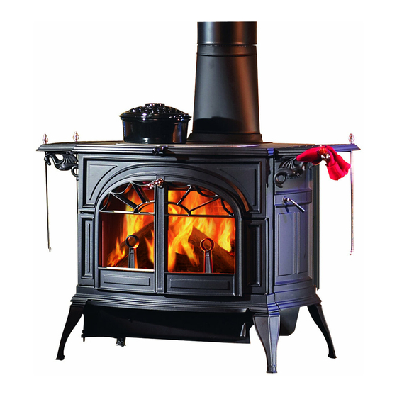
- Page 2 Model 1945 This section covers the Defiant Model 1945, built beginning in 2002. In 2002, Vermont Castings changed the Defiant stove to remove the attached legs and provide a reversible flue collar. The model designate changed from 1910 to 1945.
- Page 3 CFM Corporation Replacement Parts 1693 / 803 CFM Corporation reserves the right to make changes in design, materials, specifications, prices and discontinue colors and products at any time, 1693 without notice. Defiant 1945 Defiant Woodburning Stove parts Model 1945 8/02...
- Page 4 CFM Corporation Replacement Parts Defiant Woodburning Stove Model 1945 (continued) Item Description Part Number Item Description Part Number 62. Primary Air Valve 1307412 11. Refractory Access Panel 1602511 63. Thermostat Handle (Wood) 1600660 12. Thermostat Friction Spring 1201846 64. Airwash Manifold 1300627 13.
- Page 5 CFM Corporation Replacement Parts Defiant Woodburning Stove Model 1945 (continued) Shell Enamel Parts - Defiant Enamel Color Left Side Right Side Front Ashlip Classic 30001582 30001580 30001579 30001578 1300621 30001583 Biscuit 30002967 30002963 30002962 30002964 30002961 30002968 Bordeaux 30002957 30002953 30002952 30002954 30002951...
- Page 6 DEFIANT 1945 HARDWARE 120-1374 1/4-20 X 3/4” Hex Head Cap Screw 120-1337 1/4-20 x 3/8” Hex Head Cap Screw ( 2-each door hinge strip ) ( 3-bottom to side and front, 1-each side to 120-0998 10-24 x ½ ” Zinc Phillips Pan Head Screw...
- Page 7 SERVICE PROCEDURES DEFIANT Model 1945 This section covers repairs and adjustments to the model 1945 Defiant Stoves built since 2002. Most service procedures for this model are identical to those for the previous model 1910 Defiant . Wear gloves, a dust mask and protective eyewear when servicing a stove. REPLACING THE REFRACTORY PACKAGE 1.
- Page 8 5. Pry up and remove the left and right wedges. Pull the lower fireback forward and remove it from the firebox. You may need to lift it slightly to remove it. Slide the top of the lower fireback forward and simply lift it out of the firebox (Fig. 3). Fig.
- Page 9 REPLACING THE PRIMARY AIR CABLE 1. Remove the throat baffle. 2. Remove the right wedge lodged between the right wear plate and the lower fireback and bricks. 3. Remove the right wear plate (bolts at top and bottom, 7/16” heads). 4.
- Page 10 ADJUSTING THE DAMPER The tension on the Defiant’s damper is adjustable to compensate for compression of the gasket that seals the damper to the upper fireback. To adjust the damper: 1. Remove the griddle. Loosen the lock nut in the centre of the damper (Fig. 3). 2.
- Page 11 REPLACING THE TOP 1. Remove the stovetop griddle and the flue collar. 2. Use a Phillips screwdriver to remove the countersunk bolt going through the top at “A” in Fig. 5 below. 3. Use the 7/6" box wrench, and the ratchet with the 7/16" socket to remove a hex nut and the washer from the two threaded studs passing through clevises at “B”...
- Page 12 Fig.5 Replace the Defiant top...
- Page 13 GASKETING THE DAMPER/UPPER FIREBACK 1. Remove the throat Baffle from the fireback lifting it up and off the retaining tabs in the upper fireback (Fig. 6). Fig.6 Remove Throat Baffle Fig.7 Remove Lower Fireback 2. Remove the left and right wedges that hold the lower fireback and bricks in place, and remove the lower fireback brick retainer and bricks (Fig.
- Page 14 TIGHTENING THE PRIMARY AIR HANDLE The primary air handle may fall down to the half open position and feel loose. There is a friction spring on the inside of the stove that must be under tension to work. The actual air damper handle is the mechanism that holds the spring tight.
- Page 15 DISASSEMBLY and ASSEMBLY DEFIANT Model 1945 GENERAL INFORMATION The cast-iron construction of the Defiant stove uses tongue-and-groove seams to join and seal panels to one another. The stove’s top and bottom panels trap the sides, front, and back panels. You will work from the inside first, to remove parts from the firebox, then from the top down on the main stove panels.
- Page 16 DISASSEMBLY Ensure the stove is cool. Remove any ashes and dispose of them properly. Remember that the ashes and embers can stay hot long after the fire has gone out. 1. Lift off the griddle (#15). Open the ashpan door (#53) and remove the ashpan (#85). It will be a handy place to store small parts.
- Page 17 7. Remove the upper fireback assembly (#19). It is held in place with four bolts going inward from the upper corners of the outer stove back. Remove the upper fireback assembly by swinging its right end forward. Watch the left end to be sure the damper rod clears its hole in the left side of the stove.
- Page 18 15. Swing open the ashdoor and use a Phillips screwdriver to remove the two counter- sunk bolts holding the ashlip, #43, in place. Slide the ashlip forward and set it aside. Remove the bolts joining the ends to the front panel. Remove the bolts joining the front panel to the bottom assembly.
- Page 19 GASKETING If you are replacing gaskets as part of standard maintenance, refer to the Maintenance Section of the Owner’s Guide. If you are replacing all gaskets as while re-building a firebox, follow the instructions given below. Prepare parts carefully. Channels must be free of old gasketing, cement and paint, and free of dust.
- Page 20 Parts which need to be gasketed include: Part Gasket Size Gasket Part No. Left front door (Fig. G-1 & G2) 5/16” x 48” 120-3588 Right front door (Fig. G-3) 5/16” x 36” 120-3588 Front door (G-1 & G-3) 3/16” x 42” 120-3556 Griddle (Fig.
- Page 21 Fig. G-5 Flue Collar Fig. G-6 Upper Fireback 7/16” x 52” Fiberglass 5/16” x 42” Fiberglass damper to UFB Flue collar to top & back 5/16” x 52” Fiberglass UFB to top Fig. G-7 Ash Door 5/16” x 48” Fiberglass Ash door to bottom Fig.
- Page 22 CEMENTING A good cement seal in the stove’s stationary joints is essential to proper operation. It keeps extra air from entering the stove; this extra air can cause overfiring, smoking, back-puffing, or other problems. It is much better to take extra care in applying the cement than to have to go back later to find any gaps in joint.
- Page 23 ASSEMBLY PROCEDURE You will need at least 6 tubes of stove cement to re-assemble a Defiant 1945. Cut the tips of the tubes so you can apply an unbroken bead of cement to the cement channels and mating surfaces. 1. Place the stove bottom upside-down. Thread a leg leveler Fig.
- Page 24 Fig.12 Attach Ash Door Hinge Brackets Fig.13 Ash Door Installed 4. Assemble the primary air valve assembly. Put the air frame facedown with the drilled bosses up. Thread the primary air rod through the hole in the bottom of the air valve and just start it into the left top (hinge) hole of the frame.
- Page 25 5. Thread the running end of the thermostat cable down through the small hole and up through the large hole in the air rod (Fig. 16). Pull the running end of the cable over to the valve and thread it through the small hole in the centre of the valve. Pull 6” of cable outside the valve.
- Page 26 10. Cement all mating surfaces on the stove front. Put the air manifold in position on the inside of the stove front and secure with one hex bolt, ¼-20 x 5/8” long and ¼ washer (Fig. 19). 11. Cement the channels and mating surfaces on the left stove end (Fig. 20). Slide the left stove end into its mating channels in the stove front (you may need to tap with a rubber mallet) and swing the back of the end onto the stove bottom so that the hole in the inside bottom flange of the end aligns with the tapped hole in the stove bottom.
- Page 27 14. Cement the mating surfaces on the right end. Put the right end into its mating channel on the stove front (Fig. 24). It may need tapping with a rubber mallet. Swing the back end on to the stove bottom so that the hole in the inside of the end aligns with the flange on the stove bottom and mates with the stove rear.
- Page 28 17. Install the left and right deflectors to the left and right of the refractory chamber.. The narrow end of the bottom goes to the back (Fig. 26). These protect the stove’s outer back panel from the very high temperature gases leaving the refractory chamber; they must be in place.
- Page 29 The heaviest parts are now assembled. You may wish to move the stove to its installation spot at this point, to keep it lighter for moving. 20. Install the thermostat assembly in the right end before going further. Put washer, then the friction spring on the outer end of the thermostat assembly shaft, and pass the main shaft through the hole in the stove’s right side (Fig.
- Page 30 22. Install the lower fireback (Fig. 33) . Lean it back against the secondary combustion parts inside the retainers that position the bottom of the lower fireback. Slight notches in the bottom edge of the fireback fit behind these cast retainers. Tap the top of the lower fireback with a mallet to ensure the gasket makes good contact with the upper fireback.
- Page 31 26. Install the andirons and the andiron shelf by bolting each andiron into position with a washer and a ¼-20 x ½” long hex-head bolt. Fig. 35 Install Baffle Fig. 36 Install Damper Stub 27. Install the throat baffle by placing its side support pins on the brackets which are part of the lower fireback (Fig.
- Page 32 It is normal for there to be a slight noticeable smell during the first few fires, as the cement and paint cure. If possible, you may choose to run these curing fires outdoors, with a few lengths of stove pipe on the stove, to alleviate this.
- Page 33 APPENDIX #1 YEARLY MAINTENANCE SUGGESTIONS The 1945 Defiant is a sophisticated combustion machine, and regular “fine tuning” will give you the full benefits of its operating potential. GENERAL CHECKLIST • Inspect the chimney for blockage such as squirrels, nests, branches, etc. •...
- Page 34 • If the catalyst appears coated with fly ash, carefully remove the catalytic combustor. The catalyst element is contained within a stainless steel jacket (can). You may have to grasp the element with two flat bladed screwdrivers at the element ends to draw the element from the stove.
- Page 35 CHECK THE DAMPER The damper is designed to snap into a locked position. When closing the damper, push the handle past the point at which you feel resistance until it snaps into the locked position. • Place several pieces of note paper along the top and bottom of the damper and lock the damper.
Need help?
Do you have a question about the Defiant 1945 and is the answer not in the manual?
Questions and answers