
Related Manuals for HP 3456A


Summary of Contents for HP 3456A
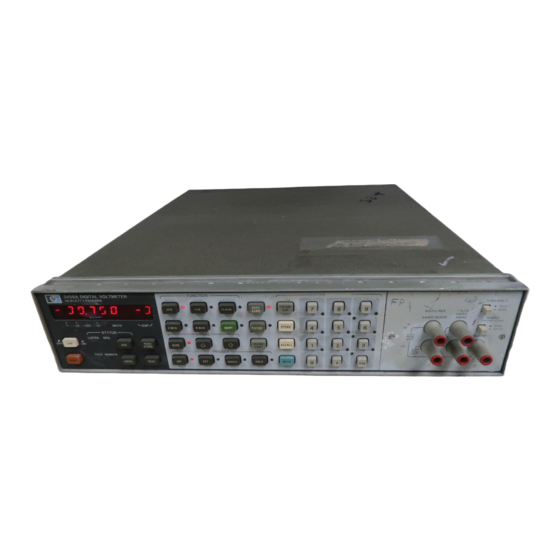
- Page 1 OPERATING SERVICE MANUAL DIGITAL VOLTMETER 3456A H EWLE TT PACKARO FRONT COVER...
-
Page 2: Manual Changes
PACKARC OPERATING AND SERVICE MANUAL MODEL 3456A DIGITAL VOLTMETER SERIAL NUMBERS This manual applies directly to instruments with a serial number prefix of 2201. Instruments with prefix 2015, serial numbers 2015A04595 and below, refer to Section VII (Manual Changes) of this manual. For information on instruments with a prefix other than listed in Section VII and on the title page, refer to the manual change sheet. - Page 3 For warranty service or repair, this product must be returned to a service facility designated by -hp-. Buyer shall prepay shipping charges to -hp- and -hp- shall pay shipping charges to return the product to Buyer. However, Buyer shall pay all shipping charges, duties, and taxes for products returned to -hp- from another country.
-
Page 4: Table Of Contents
3-118. HP-IB Description 2-33. Alti tude ......2-4 (in Appendix A) ....3-18 2-35. Repacking for Shipment ..... 2-4 3-120. 3456A Response to Bus Message ..3-18 3-122. Data ......3-19 3·124. Trigger ......3-19 Section Page 3-126. Clear ......3-19 Ill. -
Page 5: Table Of Contents
3-174. ASCII Format....3-25 6·8. Parts Changes 6·) 3-178. Packed Format....3-25 • 6--10. Proprietary Parts 6·) 3·184. Reading the 3456A's Output Data ... 3-26 • 6·)2. Exchange Assemblies 6·2 3-186. Disabling the End or Identify • 6·15. Service Kits 6·2 (EOI) Statement. -
Page 6: Table Of Contents
Optimizing Reading Rate ....3-12 8-11. A30 Board Jumpers 3-S. Interface Functions ....3-18 and Plugs/Jacks ....8-40 3-6. 3456A Clear, Home and Reset Difference. 3-19 8-12. 3456A Service Group Listing .... 8-55 3-7. Status Byte Definition ....3·20 8-13. Component Numbering ....8-57 3-8. -
Page 7: Table Of Contents
Change # 10 on Schematic 14 ..... 7-B 2-2. Power Cables ......2-2 7-8. Change #10 in Figure 6-3 ....7-9 Typical HP-IB System Interconnections ..2-3 2-3. 7-9. Change # 10 in Figure 6-B ....7-10 2-4. HP-IB Connector ...... 2-3 7-10. - Page 8 8-41. 8-73. Isolation Logic Schematic (A3) ..8-89 8-42. Slope Sequence During Rundown ..8-37 8-74. HP-IB Logic Schematic (A3) .... 8-91 Rundown Timing Chart ....8-39 Power Supply Schematic (AIOI A3) ..8-93 8-43. 8-75. FRAC Circuits ......8-41 8-44.
- Page 9 (h� �!;;V;:� 6 SAFETY SUMMARY Th, following gen.r.1 "'Ity prtcautionl mUlt be observed during ,n ph ..of operation. IIrvice. Ind ,..ir af this inltrument Failure to comply with th ... precl.tionl or with specific wlrning. 111I.h,r. in this manuII violatea IIf.ty aUlndlm of ..
-
Page 10: Installation
SAFETY SYMBOLS Ganaral Oalinitions Salaty Symbols Usad On Equipmant or In Manuals. Instruction manual symbol: the product will be marked with this Lt:, symbol when it is necessary for the useT to refer the instruction manual in order to protect against damage to the instrument. �... - Page 11 10 VOLTS HIGH. 2. Tak e a faading. Apply 100 V dc between the 3456A's chassis and VOLTS HIGH lerminal. 4. The 3456A feading should be within .00001 V of laading in Step 2. IOTE will Do the tests in the order they 8re gil/en since, for X8mple.
- Page 12 PERFORMANCE TEST RECORD 24 HOUR LIMITS HEWLETT -PACKARO MODEL 3456A .. , Performed BV D I G ITAL V O LTMETE R SERIA L • t"e Ohms Tltll Temperatuft 23°C 1.,.11. IN CuI..,. •• Set . U, •• St" , ReMi """...
- Page 13 PERFORMAICE TEST RECORD 24 HOUR LIMITS TII' p,rlQtmed HEWLETT-P A C K A R D MODEL 3456.4. � 0" . OIG I T AL V O LTMETER seRIAL Temper.ture 23-C 1°C A C V T .. , '" 'H< SIH·U, I" "...
- Page 14 H I G H. 2. Take a reading. 3, App l y 1 0 0 V dc between the 3456A's chassis and VOLTS H I G H terminal. 4. The 3456A reading should be within .00001 V of raading in Step 2.
- Page 15 PERFORMANCE TEST RECORD DAY LIMITS Tes' Performed By HEWlETT -PAC KARO MODEl 345606. DIGITAL VOLTMETER SERIAL ..Temper" '. 23°C 1°C Ohm. TIIII • .,.111 H" .."'.U, ..CI" .. ,.I" ... , ''"' 345'" PI'" RESET 0,," 0,,"...
- Page 16 PERFORMANCE TEST RECORD 90 DAY LIMITS Te" P,rfOfmed HEWlETT-PACKARO MODEL 3458A OIGITAL VOLTMETER Dele SERIAL Temperatur • • ± AC V T"t 23°C l°C ..kt·U •..T� '" """ ,'''' ' lUIA "" 0,," .. RESET .01 V D C AC V+OC V .01072 .00928...
-
Page 17: I. General Information
Bureau of Standards will be covered in a manual change supplement or revised manual pages. The specifications 1 - 3 . The Installation, Operating, and HP-IS Program listed here supercede any previously published. ming information in Ihis Manual is also contained in the Operating Manual. -
Page 18: General Information
General Information Model 34S6A 1·1. Table Specifications. DC VOLTAGE MlJimum MlJimum RHolution Input Input Rllding 4 Digi 6 Digit RHistlnn Voltlge RlnV' digitJ 5 Digit > 1010{1 :!:1000V O . l V .119999V 100 nV 10 ... V pe,k > 100 ... - Page 19 Model 3456A General Information Table 1 · 1 . Specifications (Cont'd). Response Time: < Filter OFF· For default delay 10.0 seconds!, error is .0005 input vollage step. < delault in Fitter OM: delay seconds). error is (,65 put voltage step.
- Page 20 Model 3456A General Information Table '-1. Specifications ICont'd)_ Tempereture Coeffieient (S digitl2 (% of Reading + Number of CountslfoC 1.008 + 611°C for DC component < 10% AC component (.008 + 1 21/°C otherwise 2 For 6 digit. multiply counts by 1 0 .
- Page 21 General Information Model 3456A Table 1·1. Specifications (Cont'd). 1.01 I� ID 4 Dillit PLC) Dillit PLC) Hinge Diltit PLC) 6 Dillit " PLC) 0.01 + 0.07 + 1 000 0.004 + 0.004 0.009 0.07 + 0.003 + • 0.004 l k O 0.009...
- Page 22 Can store up to 350 most recent readings. 48.0 40.00 • Volts, Filter ON 1.48 1.47 Can be recalled from the HP·le interface or the front panel. AC or AC DC VOlts, Auto·zero OFF 12.0 11.00 ',..r.III AC or AC DC VOlts, filter ON 0.95...
- Page 23 Voltml1lr Control Functions: Description: The voltmeter control function in the math section of the front panel is designed to con trol the measurement parameters of the 3456A. Included in this front panel section is the: (Xi - X) 2 - (X i 1 ) Number of digits displayed.
-
Page 24: Accessories Available
ACCESSORIES AVAILABLE. SAFETY CONSIDERATION. 1-19. The following is a list of available accessories for 1-21. The 3456A is a safety class 1 instrument (provided the 3456A: with a protective earth connection). The instrument and manual should be reviewed for safety symbols and in... -
Page 25: General
5061- 1 1 5 3 506 1 · 1 1 54 5061 1 1 55 These items included in Oigital Voltmeter Service Kit for Component Level Repair {-hp- Pan Number • 3456A 03456·698001 • 'These items are not required if a board level repair strategy is to be used. This strategy does require a Oigital Voltmeter Service Kit for Board Level Repair {-hp- Pa.t Number... - Page 26 Z40V pass the performance tests, notify the nearest Hewlett lZOY Packard Office (a list of the -hp- Sales and Service Of fices is located at the back of the manual). If the ship lOOY ping container is damaged, or the cushioning material...
- Page 27 Hp·ID connector and its pin designation, refer to Figure 2-4. mounting of the 3456A in a standard 19 inch rack, pro vided that sufficient rear support is available. Also make sure the air intake at the rear of the instrument is 2·20.
- Page 28 0101 0102 3456A contei ns metric threaded HP-IS ceble mount i n g 0103 studs es opposed t o E n g lis h threads. Merric threaded -hp- DI04 10631A, 8, HP-IS cable lockscrews must be used to DIOS secure the cable to the instrument. Identifi cation o( the two DI06 "...
- Page 29 O°C to 55°C 32°F to 131 ° F) with less accuracy . • 1 2-30. The 3456A may be stored or shipped within an • ambient temperature range of - 40C to 75C ( - 40F 167F).
-
Page 30: Introduction
-REMOTE OPERATION the instrumem. The information in the guide is most of the 3456A's operating characteristics, including remote Once you have decided what you want the 3456A to do, programming codes. the next step is to learn how to do it. - Page 31 • Paragraph 3·46 for more information. 2·Wire Ohms, and 4·Wire Ohms. Included is the SHIFT but· ton which is used to place the 3456A into the shifted func· ® Range Selection Buttons . are used to manually or tion consisting of: DCVlDCV Ratio, ACV(OCV Ratio, automatically uprange and downrange the 3456A.
-
Page 32: Self Test Operation
3-18. The 3456A's Test Operation consists of certain analog gain, offset, and digital checks when the TEST bUllon is pressed. Make sure the 3456A's input ter minals are completely floating and the GUARD switch is in the "IN" position, when selecting the test opera... -
Page 33: Display
3456A's Ratio and Math which did not pass is displayed. The displayed number is functions. also output over the HP-IB with the 3456A in remote. A ' lOO" is output when the test passes. To disable the test 3·21. Error Messages. -
Page 34: Resistance Measurement
4-wire ohms function. 3·30. AC+DC Measurament. b. Small negative voltages on measuring circuitry. 3-3 1 . The AC+DC mode of the 3456A measures the combined ac and dc components of the input signal and NOTE displays its RMS value. Other operating characteristics are the same as the ACV function. -
Page 35: Ratio
4WRll SENSE 'WAA GUflRO and LOW VOLTS terminals and connect RATIO REF LOW to VOLTS LOW. 4. Set the 3456A to the desired range or to Autorange. 5 . Place the instrument into the Ratio mode by press appropriate button... -
Page 36: Ranging
3-43. You can use the O.C. Ohms feature of the 3456A the 3456A's Ratio feature. Try this by using the set up in to measure the contact resistance of a relay. Since some Figure 3-7. -
Page 37: Instrument Trigger Modes
Depressing the button first places the state with the new measuring lead configuration. A 3456A into the Signal Trigger mode (if the 3456A is in disabled Autozero is useful in ohms measurements for a another trigger mode) and then triggers the instrument. -
Page 38: Analog Filter
Table 3-2 gives a short description of the registers and math operations. 4. The 3456A is now set to 100 Power Line Cycles In tegrated. Use the same method to store numbers into the other registers . -
Page 39: Registers And Math Listing
3456A's Settling Delay. Used lor storing the resistor value for the dBm Math operation or for recalling readings taken in the 3456A's Reading Storage mode. COUNT Used for storing the number of readings taken while in the Statistics Math operation. -
Page 40: Number Of Power Line Cycles Integrated
Digits Displayed. 3·69. Dptimizing the Aeading Rate. 3-64. The 3456A can display either a 3, 4, 5, or 6 digit 3·70. The previous paragraph stated that the Number reading. Select any of these digits using the Store of Power Line Cycles Integrated has an effect on the method in Paragraph 3-60. -
Page 41: Optimizing Reading Rate
By simply keeping the temperature of the 'elated. Among signal related lactors are; 3456A at a fil(ed value, you can nearly double the reading rate by turning Auto Zero off. The 3456A is slightly less ac· · desired accuracy (or resolution) curate but the faster reading rate may be worth it. - Page 42 " store measurement sequences in its memory, and flag the computer when it is done, lets you use both the 3456A and the computer to their best advantage. To avoid overrunning the computer with data from the 3456A, you can select...
-
Page 43: Scale
" I " into register Y. If you wish to perform an addition, 0.0000 00 x 10 - 9 to 1999999 x 10 9 . The 3456A does, enter a negative number into register If a subtraction ±... -
Page 45: Statistics
3-97. The Statistics math feature of the -hp- Model with the present reading (X) displayed on the front 3456A is used to make a Mean and Variance calculation panel. The present Variance value is in the VARIANCE of reading(s) taken in any function. These calculations... -
Page 46: Reading Storage
Reading readings is very short and makes it impossible to see the Storage is first turned on and the 3456A is triggered, by readings, store a delay into the DELAY register. A I se... -
Page 47: Voltmeter Complete
Hewlen-Packard Interface MEAN, VARIANCE, and COUNT respectively. (HP-I B). Directions for mechanical interface connec tions to the HP-IB are given in Section 11 (see Paragraph 2-18) of this Manual. You should be familiar with the 3·' VOLTMETER COMPLETE. front panel (local) operation of the instrument before 3-107. -
Page 48: Data
Model 3456A Operation TO lDW SOlJ'IC£. has priority over other trigger conditions . I f the 3456A -GUAAD A. BEST C(lNNECflON is triggered during a measurement cycle. the cycle is _EA supp!'y H�6A aborted. If the instrument is executing a measurement cycle, it will be aborted upon receipt of a Bus Trigger. -
Page 49: Status Byte
Pass/Fail measurement made is out of 3-140_ Status Byte. the selected limits. 3 - 1 4 1 . The Status Byte Message is output by the 3456A SRO bit. Note: Bit is not in this table. because il is t in response to a Serial Poll. -
Page 50: Status Bit
1 10 3. Syntax Error. A Syntax Error is when invalid pro L�3 grams codes are sent to the 3456A. An invalid pro gram code is F9. The resultant decimal number oC octal 106 is 70. f. Program Memory Error. This error occurs under the following two conditions. -
Page 51: Talk·only (No Controller)
TALK 3-157. Now that the basic HP-IB operation is known, ONLY the next thing is to program and use the 3456A over the Bus. First, determine the measurement or instrument operation you want. Then determine the 3456A's pro gram codes. The codes are ASCII characters transmit... - Page 52 3·161. etc., Hp·IB. 10. If the 3456A sent the STATUS BYTE, it did RE· QUIRE SERVICE and the program is ended 3-168. Storing into register is similar to the front panel method. First enter the number to be stored and then 1 1 .
-
Page 53: Null
Model 3456A Operalion Table Program Codes. 3·9. 3456A Cantra( PrOfr.m CodI FUNCTION Shift Function Off (Unshilted) " ACV+OCV " 2 Wire K Ohms Wire K Ohms Shift Function On (Shifted( DCVlDCV Ra ACV/OCV etio " ACV + OCV/OCV atio "... -
Page 54: Programming The Srq Mask
The End or Identify "remote" and "listen" to receive the codes. Since the (EOI) line is normally set by the 3456A prior to the Line Status Byte Message is in octal, the mask is programmed Feed if enabled. The EOI statement can be disabled over in octal by using the corresponding octal codes of the the HP-IB (see Paragraph 3-186). -
Page 55: Reading The 3456A's Output Data
Paragraph 3-165 to send The ASCII Format is chosen in this example. To output the codes. data, the 3456A has to be addressed to "talk" and the device receiving the data is the listener. Here is an exam 3·191. Home Command. -
Page 56: Front/Rear Switch Position
HP-lB. This is done by sending I : rem 722 REMOTE 3456A program codes "SW 1 " to the 3456A and then reading 2: clr 722 CLEAR 3456A its output. If "0" is output, the switch is set to REAR... -
Page 57: A Program Codes
"LlQ". the Hp·IB. NOTE d. Set the 3456A to lislen. Send the program codes to store a "2" (reading #2) into register R. Unlike regular remote operation, program memory onl y ignores blanks. Other invalid "... - Page 58 HP-IB, or when the operating capabilities of the 3456A. The following can 3456A is polled (Serial Poll). If the 3456A is set up to be used as the Operator's Check . take a number of readings per trigger, the require ser·...
-
Page 59: Section Iv. Performance Test
If a substitute is not available you may be able to ture in which it was calibrated. The 3456A should also use a calibrated decade resistor with settings that range ohm to 10 M ohm. -
Page 60: Test Cards
Guildline Model 95206 with a .01 % or ± for the 3456A. This should be done as pan of an incom better accuracy as the critical requirement. ing inspection test and at a 90 day interval, depending on your environmental condition and accuracy require... -
Page 61: Recommended Test Equipment
506 1 · 1 1 54 5061 - 1 1 5 5 • These items included in 3456A Digital Voltmeter Service Kit for Component level Repair I-hp- Part Number 03456-69800l • 'These items are not required if a board level repair strategy is to be used. This strategy does require a 3456A Digital Voltmeter Service Kit for Board level Repair I-hp- Part Number 03456-6980 1 ). - Page 62 ± .0025% with the standard's 10 V dc accuracy specification in the 6 digit mode is: accuracy at ± .000 2 5% (ten times better). If the 3456A's reading is "10.000 2 6" (.0026% high), the instrument may or may not meet its 90 day limits, depending on the ±...
-
Page 63: Dcv Test
Pressing rhe RESET button automatically order, starting with the DCV Test. Allow a I hour sets rhe 3456A to DCV, Autorange, Internal warm·up time for the Performance Tests. If the 34S6A Trigger, and 5 Digit Display. - Page 64 7 3 1 B figure 4·2. DCV Accurlcy Tilt Set·Up. Disconnect the Transfer Standard from the 3456A connectors, connect the DC Standard and the 3456A to VOLTS terminals. the Reference Divider as shown in Figure 4-2 and Figure 4-3.
- Page 65 Change the Number of Power Line Cycles In The Divider's Fine control may hove to be tegrated on the 3456A to 100 by storing "lOO" into the read justed, when its Output Voltage switch N CYC INT register. Record and check the reading.
-
Page 66: Ohms Test
9330AlIOK) turn its output on. 100 K ohm ± .001 %; (Guildline Model 9330/100K 0, 9330AllOOk) rr. The 3456A's reading should be within 0,0000 1 0 V 1 M ohm .002%; (Guildline Model 933011 M) ± of the recorded reading in Step 10 M ohm ±... -
Page 67: Acv Test
Table 4-3. 4-43. Equipment Required. d. Do the same for the 4-Wire ohms function. Leave the 3456A in that function. If any of the offset tests fail, AC Calibrator (Fluke Model 5200A/5215A) refer the 3456A to a service trained person. - Page 68 ACV Adjustment in Section V. This completes the f. Adjust the Test Oscillator's level controls for a ACV Test. reading on the 3456A to the noted reading in Step b. Set the Test Oscillator's meter switch to "expanded scale" Altarnata kHz ACV Tnt 4·45.
- Page 69 Performance Test and Adjustment Pro cedure. This may be used in place of the separate Per 5-6. The 3456A should be adjusted at a 90 day interval, formance Test and Adjustment procedure. after repair, or if it fails the Performance Test.
-
Page 70: Dcv Adjustment
One way to do it is to hold both of the anrl connect it to the 3456A's VOLTS input terminals. Make sure the " + " output is connected to the 3456A's loosened screws and pull the front panel section perpen... - Page 71 ± STA�OARO 100.0000 -3 V 5 counts reading. v. Turn the 3456A's Math off. Uprange the instru ment to the 1 00 V range. w. Uprange the Reference Divider's Output Voltage switch to 100 V. Adjust the 3456A's calibration pot ±...
-
Page 72: Ohms Adjustment
3456A's VOLTS input terminals. strument to the 6 Digit Display and 4-Wire Ohms con figuration. c. Set the 3456A to the 100 V range and adjust the in ± I strument's calibration pot "K" for a 0 1 . 000 count b. -
Page 73: Combined Performance Test And Adjustments
3456A to DCV, Autorange, Internal ment Limits. Trigger, and,5 Digit Display. 5-25. Equipment Required. c. Set the 3456A to the 6 Digit mode by storing "6" Reference Divider (Fluke Model 750A) into the DIG DlSP register. DC Transfer Standard (Fluke Model 7318) d. - Page 74 10 V output and connect it to the 3456A's VOLTS input terminals. Set the Reference Divider's Output voltage switch Make sure the " + " output is connected to the 3456A's to . 1 V. VOLTS HIGH terminal. u. Set the DC Standard for an output voltage of + 1 00 V and turn its output on.
-
Page 75: Ohms Test And Adjustment
6 Digit display and 2-Wire Ohms con figuration. rr. Disconnect the Transfer Standard from the 3456A and set the 3456A to the DCV function and 1 V range. b. Short the VOLTS and RATIO REF (4WRO SENSE) terminals shown in Figure 5-7. - Page 76 Resistors to the instrumem. k. Disconnect the 10 M ohm Standard Resistor and f. Disconnect the IO K ohm resistor from the 3456A connect the 1000 M ohm Resistor Assembly to the input and connect the I K ohm Standard Resistor to the input terminals.
-
Page 77: Acv Test And Adjustment Limits
Disable the 3456A's Autozero feature. Check the reading. d. Set the 3456A to the I V range and adjust calibra o. Set the 3456A to the 2-Wire O.C. Ohms function tion pot "L" for a 1 .0000 0 3 counts reading. - Page 78 AC Calibrator from the input terminals. m. Remove the DC Standard. Set the AC Calibrator for a .01 V. 1 kHz output and connect it to the 3456A's x. Connect the DC Standard to the 3456A with its input terminals.
- Page 79 Table 6-4 lists parts in alphameric a. Instrument Model Number order of their reference designators and indicates the description, -hp- Part Number of each part, together b. Instrument Serial Number with any applicable notes, and provides the following: c.
-
Page 80: Code List Of Manufacturers
6-16. Three service kits are available to aid in the repair ponents than is supplied with the component level of the 3456A. repair service kit or to replenish depleted inven I . Service Kit-Component unl Repair. -
Page 81: Replaceable Parts
Table 6·4. Replaceable Parts. • HP Part Reference Description Mfr Part Number Designation Number Code " 0)15 •• 66'50 1 PC 'saE�8LY_W�.I� lua� OU, .. "dO I I, J , . P I N � �flNIC p o a r TyPE tD.mEt T O �... - Page 82 Table 6·4. Replaceable Pans (Cont'd). Reference HP Part Description Mfr Part Number Designation Number Code tJ� 'rhl '.c, ,,'12 ,".�· 'ou.u,. ,"U'"BuTTD" '"ITC" 110", .. , ,o.".',"j� 'ou ••• ,. 'US"BUT10� '.t. "01,1 "" AI'2� SO"u··oh 'U, .. BUI100< 50.0." "...
- Page 83 Table 6·4. Replaceable ParIs (Conl'd). HP Part Reference • Q ty Description Mfr Part Number Designation Number Code .,t_, " • UtR, IOO� ISUo 00_1S l � ·� n SQ • " 'SCII) UO 1.0050 '"' loO�' �O-)S no So .onl·"n5u...
- Page 84 Tablo 6·4. Roplo.ooblo Parts IConl'd). Reference HP Part Qt y Description Mfr Part Number Designation Number Code "�Cl ',711" -10. �voc ,. �l' � 0) '0_0301 15" Dns.�tl l v ' 5 1 • ..711'.·IU I O�DC 5'11" •• JOlno, · �...
- Page 85 T.bl. 6·4. R.pl bl. P.rts (Conl'd). •••• Reference HP Part • Ot y Description Mfr Part Number Designation Number Code '�'·Lao"'· ltoln I � I � " ' 9 6 0 " 11� '�"lUU'l �1 l" • � D ..
- Page 86 C E . 'lOtIO. Cl'O._'IO '_101 'S010C C(� "" 0 , .. n·nu lO" � · 111. 'IOCSO. 0110."07 CA·IC"OIl.,.O HP' . . 5 1 IOftVOC erR 0 •• ]0 It.h OI.o·nDJ )1" UOC'IU O'"O·.,Ot t'_.CIIOII.'"O ,.'1 IOU�OC C�� •• lft ..
- Page 87 Tabla 6·4. Raplacaabla Parts (Conl'd). • Reference HP Part Ot y Description Mfr Part Number Designation Number Code IUi.UU 1,,')0 1 i � 1 ·��bl • 1�·'1> IRn.oo,. " N_CHA" IU'jl\ ... nuo, J·'E T D."v�t '0.°1 I �S!o·�.'� T�."5IS10R '1-C"""...
- Page 88 Table 6·4. Repll.llbll Plrts (Conl'd). Reference HP Part Description Mfr Part Number Designation Number Cod. 'u-ui Ulhun 0 1 1 1 1 CllOn UU\., .u,.,u. 0 1 U I Cll0U .Ublon (lIOU '10'1" 0 1 1 1 1 0 1 1 1 1 ,,,It, ..
- Page 89 6·4. Replaceable Part. ICont'd). Reference HP Part • Description Mfr Part Number Designation Number Code ''''Ih G"''''�U' lC.ft'·IO� C " ' / � . I O . 1 J).I., SU� lelh_I01 " nUU' ,'5._ HSlIlO� , l l h , 1"...
- Page 90 Tabla 6·4. Reple.aable Parts (Cont'd). Reference HP Part Description Mfr Part Number Designation Number Code �'08H •• le GHE TTl �, �UD DUAO 1.1�' '�'·l'·O" le (OM'A�A'OR [� D �.OIP.' l �S")" • ouac 'U '" 'IG .. [O�D G 'l�l�l�t...
- Page 91 T.bl. 6·4. R.pl bl. P.rts (Cont'd). •••• • Reference HP Part Description Mfr Part Number Designation Number Code �).� ,u".u�n �t ••• [�IL,.�(,[.(�t[ .0_.0, ,IUO Ul§ �·I. �f FlelO "" A5SE�eL' �fPA1�A8LE. ASSEMBLY MUST O�OfRfD. uu.· •• Uo 't '�'E�IL'·IN'Ul'D LO'IC o)d.·."')�...
- Page 92 Table 6·4. Replaceable Parts (Conl'd). HP Part Reference Description Mfr Part Number Designation Number Code J.�'� ',OH' CO��ECTD� u,eo I.'I� , • U' •• �� 'Oil II,r ISO" liShllt' 16"0 , '011 "PE n l ·1 CONI'CT·CONN 'OII.I" E 'f� CR P ,,,eo , '0"...
- Page 93 Tlble 6·4. Repllceeble Parts IConl'dl . • Reference HP Part Description Mfr Part Number Designation Number Code '''il l �5 l}" ,UIO " •• �, JOOW"( �I(' ('�_Cll0'." O 0 1 6 0 - 2 1 5 0 • CI'I(I 'O'.'IO lID"...
- Page 94 Tabla 6·4. RaplB.aabla Parts {Conl'd). Reference HP Part Description Mfr Part Number Designation Number Code 10 51 .IS. 'c Te IOO/.SOo D i l l ' �UU'O. • • O" ,.U35 IIU1l10� I,'OK So'· CI .I 'I.ID.'"'''' hO_' Tt· .. ·lta un U 0 ..
- Page 95 Table 6·4. Repleceeble Perts (Cont'd). • Reference HP Part Description Mfr Part Number Designation Number Code U. "� 0.0 ..\ 1 .IZ5� Tt,O,.\OO ••••• re.OU\oo 5 1 . RUUTOII IIOK 11 ,.ISM Tt.O._\OO Don.uU fe_Q._ln ."1110. I � 11 .115�...
- Page 96 IConl'dl. Tabla 6·4. Rapla abl. Parts •• Reference HP Part Description Mfr Part Number Designation Number Code ,50010" 'oUH " " 'UI. C.�.tllD�.�.� lU� •• I O I Dt T. C01JA,OIJ1V).'J. ,nw' hiD tV'C!To-.no '�YDt O l.,II IY " " 01 . 1 ' 1 1 "...
- Page 97 6·4. R.pl bl. P.rts IConl'd). r.bl. •••• Reference • HP Part Description Mfr Part Number Designation Number Code "UClLLhlfOU' u�u .a .. , 'Hh.Ulel C�·UI'.I"'U.�O. n" Q OU'�.OO'PI •• ,," ,0 CHA.SU_IH'uuo. GUlln.oUTGu· OU5hO�IU GAIJSSET-OUTGUAlto OHH-00105 .1"n,'�D"T �)I'5hOU�1 u ...
- Page 98 Replaceable Parts Model 3456A .OTE The MP DesigMtions used on this pege epp/y 6·1. only to those pens celled out i n Figure MP1 5 i!l)"'�- MP4- M P 1 8 ...
- Page 99 Model 3456A Replaceable Parts • IOYE Designlltions uSlld on this pllge apply 6-2_ only to thosll parts Clllled out in Figure ." � .. ri<aI ... . ." Tootn $.ancIot! ...� �, ." W_.'n' ." "...
-
Page 100: With Pc Boards Removed
Replaceable Parts Model 3456A NOTE The MP Designations used on this page apply on ly to those parts called our i n Figure 6-3. • MP' 2 • • • • • · · Pert Oucription Dnigneti6n Number 03456-04 1 0 9... - Page 101 Model 3456A Replaceable Parts NOTE 6-4 . Designa(ions used on this page apply on those parts called out in Figure M P 1 0 • Board !" Ref,r,ne. ·hp· Part D,scription IlImber Duignltion A" 03456-04109 Power Shield • 1 390-0458...
- Page 102 Model 3456A Replaceable Pans 1II 0 TE 6-5_ Designations used on this page apply on ly to those parts called out in F i g ure � R,I,rUn -IIp- ',n Dui nllioR lII . mMr 2 5 1 0-0192 Screw-Mach 8·32...
- Page 103 Replaceable Parts Model 3456A NOTE 6-6 lA, 8, & Designations used on this page apply on ly to those parrs cafled out in Figure A. Side View of Chassis Showing Handle/Hardware . B. Side View of Chassis with Side Cover Removed.
-
Page 104: Front Assembly (Inside View)
Replaceable Pans Model 34S6A /II O TE 6· 7 fA & BJ. Designations used on (his page apply on ly to those parts called out in Figure 0" • • • • . • ;" • • "' A. Front Panel. B. -
Page 105: Front And Rear Panel
Model 3456A Replaceable Parts JrlOTE 6·8 (A & 8). Designations used on this page apply on· Iy to those parts called out in Figure A. Inguard Chassis Hardware-Front. B. Rear Panel. RII.r,nee ·hp· Pert Dncription Dui nllian Number 03456-0 0 1 0 2 C hassis·1 nguard·Left... -
Page 106: Front/Rear Switch
Replaceable Pans Model 34l6A NOTE 6-9 (A & BI. Designations used on this page apply on ly to those parts called out in Figure A. Inside View of Front Terminal Assembly and Guard Switch. •• B. Front/R r Switch (F/RI. p,rt •••... -
Page 107: Assembly And Ac Power Switch
Model 3456A Replaceable Pans NOTE 6·10 (A & BI. Designations used on (his page apply those parts called out in Figure .' � ,1\ "t. • ,!. , ,, A. Inside View of Rear Terminal Assembly and Guard Switch. B. AC Power Switch. -
Page 108: Diode, And Bracket
Replaceable Parts Model 3456A NOTE 6-11. Designations used on this page apply on ly to those parts called our in Figure ·hp· Reference Pari Oescriplion Dui Aalion Number Bracket-Transformer 03456-01201 Screw· Pan-HO 051S-0216 Mach M4 0.7 SOMM-LG CRS .).10 Diode Assembly Bridge 1906-0205 Figure 6- 1 1 . - Page 109 47.5K ohms for R424 and R427, and R425 and R426, respectively. They where changed to improve the 7-4. To adapt this manual to your 3456A, refer to Table A/D Converter's Overload Circuitry operation when 7-1 and make aU the manual changes listed opposite the 3456A's is configured to the 50H2 power option.
- Page 110 Model 3456A Backdating e. Page 8-83/8-84, Figure 8-70 (Schematic 9, Main 7·13. Ch.ng. #4 Controller Schematic). Change Address Line AlO con 7-14. For serial numbers 2015A00950 and below. Use nection as shown in Figure 7-3. new part number (1855-0460) shown in Table 6-4, when replacing A2OQ406.
- Page 111 •...
- Page 112 Backdating Model 3456A 7·15. Changa #5 4. Change R21 from 9.09K ohms to 6.98K ohms. Do not change the resistor if Cl I is missing from 7-16. For serial numbers 2015AOl 865 and below. All the A40 assembly or hybrid U3 has been replaced.
- Page 113 7·'9. Ch.nga #7 manual. I f a ROM (A4V5, V7, or V8) is to be replaced in the 3456A because of a failure, make sure the new 7-20. For serial numbers between 2015A01866 and ROMs used as replacements are the ones listed in Table 20ISA0290S.
-
Page 114: Individual Rom Signatures
0111 ing: Pin' Signll�r. B" h. Turn the 3456A On and check the following 2AP3 signatures. If any signatures are bad, try the recom mended integrated circuit{s) in the given order. Replace FFP5 the one on the left first and then replace the one next to C09F it, if the signature was still bad. -
Page 115: With Pc Boards Installed
7-26. For serial numbers 201 5A04595 and below. This h. Page 6-22, Figure 6-3 (Top View of Chassis with change applies to 3456A which did not have their Fan PC Boards Removed . Replace Figure 6-3 with Figure (Bl) removed. I f the Fan is defective and needs to be 7·8. - Page 116 HP-IS Connector used to connect to HP-IS. Ratio Ref/4WRO Sense Terminals - are used for the Ratio Reference Voltage or 4-Wire Ohms measurement. ® HP-IS Address Selection Switch - Sets 3456A HP-IS Ad dress. Volts/2WRO/4WRO Terminals input terminals for the ACV, DCV, ACV DCV, and 2-Wire Ohms measurements.
- Page 117 3456A Model Backdating NOTE 6-3. Designations used on this page apply on ly to those parts called out in Figure '" !!!!I! !! !> • • • MP11 • • " •• ·hp· Pen Reterenee Descriptiun oesignetion 03456·00101 Chassis·lnguard-Right 1251·6184...
- Page 118 Backdating Model 3456A j. Page 6-27, Figure 6-8 (Inguard Chassis-Front and k . Page 6-30, Figure 6- 1 1 (Power Transformer and Rear Panel). Replace Figure 6-8 with Figure 7-9. Bracket; ec.). Replace Figure 6- 1 1 with Figure 7-10.
- Page 119 Model 3456A Backdating NOTE 6·' ,. Designations used on this page apply on· Iy to those parts called out in Figure · R.I.r.nc. Description Numbtr Onignelion 03456-0 1201 Brack.et-Transformer • � 051 5·0216 Screw·Mach M4 0.7 50MM-LG Pan-HO 0340-0580 IO$ulalol·XSTR THRM-CNOCT 03456-01202 Bracket·Regulator...
- Page 120 Model 3456A Backdating "" .1It> PHI 7·27. Chang... 7-28. For serial numbers 2201A04795 and below. Page A4Ul0 1 8 1 8 · 1 2 1 3 IC NMOS 8192·81T RAM 6-6/6-7, Table 6·4 (Replaceable Parts). Change RAMs A 4 U l l 1 8 1 8 ·...
- Page 121 Manual must be followed. Any servicing 8-13. The 3456A can be separated into two main areas, or adjustment should only be performed by service the Inguard and Outguard Section. The purpose of the trained personnel.
- Page 122 RMS Converter. The Converter changes the input voltage to a dc voltage and then applies it to the Input c. If the 3456A is set up to take a dc reading, the in Amplifier. Range attenuation and amplification is done put is applied at the VOLTS input terminals.
- Page 123 The information is then processed by the Main Controller and is displayed on the front panel and/or TO INPUT SWJTCNIHG �NO AC CONV{RlfR sent to the HP-lB. If a math feature is selected, the math calculation is done before the recalculated reading is displayed. "...
- Page 124 Model 3456A Service 8-32. 100 V, and V Ranges. Relay KlO3 (a each having its own numbering sequence. Table 8-1 low thermal relay) and Fet switch Q l 16 are enabled for summarizes this numbering s!ructure. Note that the 600 the 100 mV to l O V ranges.
- Page 126 DC Input Amplifier. AZ is prevent amplifier slewing, the bandwidth of the input enabled when the 3456A is first turned and also when signal is limited to approximately 3 kHz by the Input the front panel reset button is pressed. Two separate Switching Circuits.
- Page 127 O � " �l " « • " �� " • • - " � " " W " • " < - " < O � . - > . • • [ � , -, � , �...
- Page 128 8·48. ANALOG·TO·DlGITAL IA/DI CONVERTER. '0 v \ o } " 8·49. General. 1 000 8-50. The 3456A Digital Vohmeter uses a technique called Multi-Slope to convert analog input signals to All Ranges digital information. This technique is called Multi-Slope Ohms...
- Page 129 Model 3456A Service 8-56. Figure 8-10 shows an initial runup (S - 4) of 4 8-53. During Multi-Slope 11 Converler-Runup. AID counts for a . l PLC selling. For I , 10, and 100 runup, the input signal is applied to the integrator for a PLC settings, the S 4 slope lasts for 8 AID counts.
- Page 131 Service Model 3456A $toql.ncl II� A ..62 n ... for I PLC " 1-5�1 -IOY Counts • • . . . ALE·s 1300 AID Counts 1248 1 300 Total of Total time for S ± 4 slopes is...
- Page 132 Service Model 3456A 8-72. Rundown uses four differem slopes to achieve highly accurate measurements of the residual voltage 4) is the within a short time. The first slope (called S steepest and it continues for an integer number of AID _ 1 0 fUO [OU�,...
- Page 133 Service ModeJ3456A Slopes. The final three 8-77. 5 - 3, 5 + 2, and 5 - 1 slopes that follow the S 4 slopes always cross zero in ± the direction shown in Figure 8-2 1 . This is done for two reasons: to oplimize the S 3 , S + 2, S slope switch...
- Page 134 Model 3456A Service are in parallel to minimize the input resistance. During that they will be closed when Q402 and Q403 are open I� those time periods when the input runup FET's are and vice versa. open, FET switch Q404 grounds the input to prevent the gates of Q402 and Q403 from becoming forward biased.
-
Page 135: Troubleshooting
Service Model 3456A those 500 series numbered components in the small put signal magnitude plus the offset value, hence the re reference section on the A20 board and two other com quirement for that additional dynamic range. ponents (variable resistor R614 and Switch S60I) that are physically located in the calibration section. - Page 136 B·113. General. The voltage 8-118. Reference Voltage Section. 8-114. The Ohm's Current Source in the 3456A supplies regulator is an inverting amplifier that has a near-zero a dc reference current to the unknown resistance during volt input. The voltage divider (fine-line resistors) bet...
-
Page 137: High Voltage Protection Circuits
Model 3456A Service 8-121. For a I K ohm range measurement, FET switch unknown resistance, is calculated by the Outguard Q209 is on. At this time I mA of current flows through Logic for these two ranges. Also note on Table 8-7 that the 7.5 K ohm fine-line reference resistor to drop the... -
Page 138: Simplified Aid Converter Schematic
TP40l I N T E GRATOR OVERLOAD D E T E C T O R ." (403 L O G I C LOVL INGUARO U 4 0 9 a , c , d 0402/403 TP403 ZERO 0 4 0 6 TP405 COMPARATOR U 4 0 5... - Page 139 USQ4 rONvERTER AC C O N Y E R T E R A 2 4 - t 2 V � R E f E R E N C E BOARO O H M S CURRENT S O U R C E T O INPUT A M P L I F I E R �...
- Page 140 � �� ;� � � f ;;: � .. : ::: 1 ..· ,]...
- Page 141 Service Model 3456A 8-134. Figure 8-29 and 8-30 illustrate how this circuit Offset Compen 8-129. Offset Compensated Ohms. operates. The negative voltage swing at the output of sated Ohms makes two measurements on the circuit the Input Amplifier is normaUy between 0 V and 12 V connected to the input terminals.
- Page 142 CURRfNT OHII ' S SOURCE lCurr�nt 5.nn 8-140. The 3456A uses operational circuits rather than a thermal element to convert the signal being measured R ,..." I to a dc equivalent of its true rms value. This type of rms...
- Page 143 Service Model 3456A to go to - I S V (FET turned off). With a high logic in the proper feedback resistors. These fi x ed gains are set put signal, the comparator's output transistor is turned by the I M ohm input resistor and the feedback off and the output rises via the pull-up resistor to resistors.
- Page 144 Service Model 3456A low level signals at the higher frequencies are reduced. the current source for U5's feedback loop. QI5 provides The total circuit is an inverting amplifier that deals with quick slewing for high crest factor measurements. currents rather than voltages.
- Page 145 QI6A and QI7A in the Squaring Amplifier. Diode 8· 1 7 1 . RATIO MEASUREMENTS. CRI5 balances out the voltage drop across the base.. emitter junction of QI6B. 8-172. During a ratio measurement, three complete measurement cycles are done. The first cycle is either a 8-169.
- Page 146 0 < " S � · " < << '> << > - , < ... - ..-' � :> 0..1 _ <> c: ..• - < • < w ;; � 0 :�; '" , % , ' __ I...
- Page 147 Model 3456A Service ......_ .._._ .. _. __ ._ .. _. Kt Dl 3456,41,...
-
Page 148: Simplified Block Diagram
Service Model 3456A 8·176. INGUARD lOGIC (A30 BOlrd). 8-179. Set-up information from the Main Controller • (Outguard) is received by the Inguard through the Isola 8·177. Generll. tion Logic. This information is used by the Inguard microprocessor (PP) and the "Range and Function Con... - Page 149 Model 34S6A Service Refer to Figure 8-39 (Isolation Logic, 8-183. Receiver. Refer to Figure 8-40 (Isolation 8-186, Transmitter. Receiver) for the following circuit description. The Logic, Transmitter) for the following circuit descrip serial data received from the Outguard Logic through tion.
- Page 150 ;;:. :;: :;: :;: ;;:. :;: � � - --I:f .."' ;;i � ;: :! - "' < -' > " • > " < N...
- Page 151 Service Mode1 3456A • [1 . "IC��PMCn!Q� " !IN�LE �IRE " SHQMQARY ." " U19_ .. , "" S1<lfl �HlSIU ' PAfIIILLfL • '5� '" • !!ftJAL ·sv, .. 0 ,"",." ,.,,, .�� , "" , ., .. , '"...
- Page 152 Service Mode13456A in the Input Switching circuit. Refer to the Input Swit· transferred from Port Expander U702 (via PT5 1 . PT52, ching sections under DC Volts Measurement for addi· PT1I, PT12, and PT73) to Decoder U70 1 . This data is tional circuit details regarding the Autozero and Analog expanded from 4 line-input (PT11 is load enable line) to Filter circuits.
- Page 153 can be monitored at TP3. The output from U I 2c and 8-201. F R AC's Function During Rundown. Figure UI2d provide the 2-phase crystal reference inputs for 8-42 (Slope Sequence During Rundown) illustrates the U I 3. The output from the crystal reference is also fed slope sequence during rundown and the FRAC actions (via inverters U l 2 f and U 1 2e) to the circuits that that occur during rundown that control the slope...
- Page 154 NOTES Slopes not dr8wn to scale for illustra tion purposes. SLOPE Input signal volt8ge to integrator i s switched off during rundown. $ . � SLOPE " ... � 17 AlC c( ' $'2 SLOPE COUMTS 'i-I "All 18 .vD 5LOPf MX I 6 oVO flN1IL ZEM...
-
Page 155: Rundown Timing Chart
Model 3456A Service Chart. Figure 8-43 is a timing 8·210. FRAC is disabled at the end of the last 5 + 0 8-206. Rundown Timing chart that illustrates the order in which the rundown period following the 5 slope. The S... - Page 156 AID Converter test. To ir.lplement this test. When the LOVL (Low True, Overload) 8-221. LOVL. the 3456A power switch must be turned off and line from the AID Converter circuit goes low signifying then on again after the P36 Jumper plug is posi...
- Page 157 :=� . � ��� . ",...
- Page 158 c" I � • < 0" �� " <...
-
Page 159: Simplified Block Diagram,
HP-IB circuits (A3 Board) ....8·285 HP-IB Interface Adapter ... . 8·287 sent to the ItP. - Page 160 A4 boards. A 3 MHz output (2x f o , A4UI4 pin 5 ) is used as an input to the circuit that generated OBE. d. When bits 14-1 I are 1 0 0 0 respectively, HP-IB is selected. The HP-lB Interface Adapter (A3U9) has 8 8-238.
-
Page 161: Obe Stretcher, Timing Diagram
" 8-241. The ROM's and RAM's and some other com " ., .. " .. , ... ,"" ... OHM' • ponents used in the 3456A are designed for use with a I wo'" ... ,"" I " I!' •... - Page 162 .,� � ; � .� "" "' - - "' .. "" ., '" "' - ..0 "' 0.. 0 " "" ... o � � • >1 c: :::...
- Page 163 15 through 1 1 are 0 I 0 0 0 respectively and clock input for A4U20D (one-shot multi vibrator). U20b True VMA is high. the HP-IB Select line is strobed. drives the front panel "sample rate" LED. Lines.
- Page 164 I. Hp·IB Select (Un, J! . in 15). The Hp·IB Select A3UIO, a parallel to serial shift register. Data is loaded strobe line is the chip select (CS) for the HP-lB Interface into UIO when a high to low transition occurs on its Adapter (A3V9).
- Page 165 8-263. The Byte Available pulse from U l 7 b goes to flop U22b outputs a high to pin 14 of buffer U2S (goes A3U16, pin 1 8 (data line 07. see Schematic 1 3 , HP·IS to data line 05) whenever a Y' key is pressed. This ar...
- Page 166 Service Model 3456A 8-276. The Display and Annunciator Strobe pulses oc on this Keyboard Strobe line assures that this line is high cur 1 00 ms after the data is strobed to the output of the when it is not being strobed.
- Page 167 Figure 8-56 for the external and internal Main Controller circuits (A4UI4). The interface be tween U9 and the HP-IB is via DID I-DID 8 bus (Oata Input/Output) and the Handshake (3 lines) and Management Comrol (5 lines) lines. Four tri-state Bus Transceivers (A3U 12, U7.
- Page 168 The position of switch contacts 1-5 is tify faulty logic nodes for troubleshoOling to the com used to set the HP-IB address for the 3456A. Switch 7 is ponent level. A choice of different strobe connections is available for the start/stop input to the SA test equip...
- Page 169 8-304. +33 Volt Circuit. The + 33 V Unregulated cir cuit ( + 33 to + 46 V range) uses a voltage doubler that is 8-297. For isolation purposes, the 3456A has two similar to that used by the + 1 8 V circuit. The + 5 V separate power supplies.
- Page 170 This signal is used by the Main Controller regulator (UI). The 6.2 V zener diode (CRI) connected ItP and the HP-IB Interface Adapter. The output of the to the output of voltage regulator, U I , provides over voltage protection for the 5 V line going to the full-wave rectifier ( + 7.5 V to + 1 5 V) is applied to...
- Page 171 Inoperative Annuoci8l0r Outguard 8·313. Board Removal and Installation. Inoperative Kevboard Outguard Combined Displav, Annuociawr. 8-314. Most Printed Circuit Boards in the 3456A can be and Kevboard Failure Outgu.rd easily n:movcd, since the boards are held in by Outguard ' Failure Hp·IQ...
- Page 172 CONNf.CTED TO I"GUARD SHEET "ETAl • • +3311 -lB j + 5 11 • P I B - - - 1 5 V '" 0 SHEET METAL GROUND P�TH COHN(CHO T O IHGU�1tD SH££T IoIETAl COOIJ«CTED TO INGU.lRO SH[ET IoIETAt. WHENU$(O INPIJ1' ::�...
- Page 173 3456A's Inguard Logic and AID Converter. The In guard Isolation Logic troubleshooting is also in this ser Make sure the 3456A is turned O f f and vice group. This group is also selected for certain test power is removed from the instrument failures (see Paragraph 8·332).
- Page 174 . 1 0.40000 NOTE Make sure no connection is made at the 3456A 's Input Terminals and the GUARD switch is in the "IN" position during the a. Test # 1 . This test checks the Program Memory Test mode.
- Page 175 Ohms Converter, Input Amplifier, or In troubleshooting. put Switching. To determine the circuitry. make sure the 3456A is good on the 1 00 V and 1000 V Ranges in the This test fails if either the Inguard or 8-338. Test 113.
- Page 176 Mnemonic Definitions. Origin Dntiution Address Latch Enable A30-U 1 3 ( 1 ) A30-U l a( 1 I . U6b(121. U7b( l l I. U 1 4 a ( 1 ) , U 1 4 c ( 1 0 ) Address Latch Enable.
- Page 177 Mnemonic: Definitions (Cont'd). O,liliti;1 Dtiltiution Origill A30·U9(51 A20-U40B(41 High True, Slope Bit B A30·U9(31 A20-U40B(61 High True, Slope Bit C High True, Range Bit " Ohms ( 1 0 MO) & AC ( 1 .0 VI (Decoded from HL & HMI A20-U201a(5), A20·U701141 U202c(8);...
-
Page 178: Mnemonic Definitions And General Schematic Notes
GENERAL SCHEMATIC NOTES RESISTANCE IN OHMS. CAPACITANCE IN MICROFARAD$, INDUCTANCE IN MICROHENRIES UNLESS OTHERWISE NOTED ASTERISK OENOTES A FACTORY·SELECTED VALue. VALUE SHOWN ON SCHEMATIC IS TYPICAl. ENCLOSES FRONT PANEL MARKING. ENCLoses REAR PANEL MARKING •• CIRCUIT ASSEMBLY BORDERLINE. OTHER ASSEMBLY BOADERLtNE. ALSO USED TO INDICATE MECHANICAL INTEACON NECTIONS (GANGING). - Page 179 � < � � � � � • - - , � .E._ --------- --.�-.,...
- Page 180 A20 Board · Input Switching · Component Locator Table. Component Col. Component Col. Component Col. Component Col. C l 0 1 0 1 0 1 Rl l 1 R143 0- ' 0 1 0 2 R l 1 2 R144 Cl02 R 1 4 5 C l 0 3...
- Page 181 '''1'' �l '" -�) �- R 1 5 0 I S P O S I T I O N OF SELECTED FACTORY -ClOI- "101 �1 01 � 1 0 1 " 03456·66520 (INPUT SWITCHING) 8·65...
- Page 182 !! r _ ._- : i ! l � . . • I� t� f� • • • • • • ! ,� �. &, ' • 1 ·1 I l" I li I • • • ,. I .. ,...
- Page 183 Board · Ohm's Current Source · Component Locator Table Component Col. Component Col. Component Col. Component Col. C201 P 1 6 R20S R60S C202 P 1 8 R209 R609 C203 R2 1 0 R 6 l 0 C204 0201 R21 1 0202 R2 1 2 TP201...
- Page 184 --- F ZGl--, " • -CR20'2-:.. 020! Ol08 CRlOI • Ol05 :E�8�: UZDO 0204 0 0207 0 0 0203 - 1 1"- 8 � 8�O 0206 -C202- Jttf!ru!7 JHf!ruI8 � : 1 111: -R218 - := JtI�6 JMf.ill5 -'m- - 1�--R -RH4- 8 ·�...
- Page 185 i � i � � I I � �.; ___= .. �� __ �� __ �� _ _ �� _ _ �� _ _ ��__...
- Page 186 A20 Board · Input Amplifier · Component locator Tabla. CompolMlnt Componlnt Col. Col. Component Col. Component Col. C301 0301 R 3 1 3 R61 1 C302 0302 R 3 1 4 R 6 1 2 C303 0303 R 3 1 5 R 6 1 3 C304 0304...
- Page 187 ::U!: 0311 0310 • 0309 - ' W- a } Q � 0308 U200 C303 00 303 -t,�O\ 0305 01305 0030l -(RlOZ" -11. 1 "- 0301 0 -Rl19- · 12-� ..., (R30� -R313-o - f\ 1 1 - • � -R l 1 - ..
- Page 188 • • .� .� ' . . I !: �_ _ .. _.. :��._ _ .. _ .. _ .JI �.-...
- Page 189 A2D Board · AID Converter · Component locator Table Component Col. Component Col. Component Col. Component Col. TP401 A�B C401 P 1 5 R4 1 1 TP402 C402 R 4 1 2 TP403 C403 B�C R4 1 3 A 4 1 4 TP404 C404 0401...
- Page 190 " -R431- -R430- • -R429- • -1'142 6 - • � -(410- • • 0 Q.. :11: -R433- " ::> -1'1425- • -R432- -R424- -R422- �, -R 42 0- OO40B • ·(1'140 -1'1419- � -(404- • -R411- - 1'1 4 \ 0 - -R41B- •...
- Page 191 �·r � • < " ___ • _ __ _ _ _ _ •...
- Page 192 USOO JIIPR50E> JIIPRSOZ JI1Pfl.SOS JI1PRS04 JI1PRS03 N � • " �O " " o � < � 1EIT2I "0 • • • . " < 0501 CRSDl CRS03 (501 PZSB P2SA _l? 0 0 7':. -R50 3- -R50�- " " - 11.
- Page 193 �.:.
- Page 194 ' : - .." : ;:;:;:;:;: ' : : : : : .: : .: : .: : .: : .: : .: : .:;.;.; . ;.;. . : « . ; '. : "...
- Page 196 See Schematic 3, Pl 5171. -(70\- " :E��8� ·"8'· 00703 03456·66520 (RANGE AND FUNCTION CoNTRol lOGIC) A20 Rlnge Ind Function Control Logic + 5 V T, .. CD4555BF U701 U702 P8243 8-77a...
- Page 197 • • 1 1 , " " ± � � '" ----"" -- �---------- � �<...
- Page 198 COlllponent LOCItor rlble C�lII p o ... nl Col. COlllponent Col. COlnpolll n l Col. Component A l 0 JMPRl A l l '- F JMPR2 A 1 2 JMPA3 A 1 3 JMPA4 A 1 4 JMPA5 A 1 5 JMPA6 A 1 6 JMPA7...
- Page 199 -" � < � -C9- -f\Z- fl l • CR2 - -f'1I0- -R9- � [I=== == =;.�= =: :JI � 03456·66540 A40 Board + 5 V T , po T , po + 15 V ·)SV + 15 V +5 V ·...
- Page 201 A30 Component Locator Table Component Col. Component Col. Component Col. Component Col. JMPR I JMPR R 1 3 JMPR R 1 4 R 1 5 P 2 1 R 1 6 R 1 7 U l 0 R 1 B U l l U 1 2 U 1 3...
- Page 202 8-81b...
- Page 204 A4 Component Locator Table Componlnt Col. Componlnt Col. Col. Compon.nt Col. CompoNnt • R I O U l 0 C l 0 E l 0 U l l Rl l C l l U 1 2 R 1 2 C 1 2 U 1 3 R 1 3 R 1 4...
- Page 205 £ [J . • • , : D � " : El l "" J1-""'"' "' " . ". 0: ", ' U<fD USfO " E l - Ci: - " - 0 - � " " [J [J " ' l' B ' '"...
- Page 206 i�...
- Page 207 A4 Component locator Table Componlnt Col. Component Component Comp0nlnt Col. Col. Col. • • • C l 0 E l O R l 0 U l 0 C 1 1 R 1 1 U 1 1 C 1 2 R 1 2 U 1 2 R 1 3 U 1 3...
- Page 208 " €i - n - � B " , , , �D CI�CIIIT 10001 "" � 03456·66504 A4 B"rd T, po T, po ..U 1 8 I • SN74S74N U 1 . U2 Not Used .
- Page 209 " "' "' " "' ii ; � � ;;; H " . , . . I •...
- Page 210 G:C G:C � EL 05 4 OS£. '" OS'! '" (RIO � � CRI8 (Rt5 CR16 (1117 (1'120 (1'11'3 � � � CR26 (1125 (1123 CRZ4 EC EC EC EC ]�sr.-zc 03456-66502 A2 Component Loc.tor T abl, Component Col. Col. Componlnt Col.
- Page 211 O f-! ! · - f-! ! " , · e- " f-...
- Page 212 A3 Component Locetor Table Component Col. Component Col. Component Col. Component Col. R 1 D R 1 1 R 1 2 R 1 3 R 1 4 R 1 5 U 1 D R 1 6 U 1 1 R 1 7 U 1 2 R 1 8 U 1 3...
- Page 213 2-C IRCIJI T SI DE rEYE�1 -26 -RU- -1123- A> -R17- -RI8- - 117 - . " - R6 - 7 + 5 '1 "n ." - ( 1 - - Rl - + 5V TWO-CONDUCTOR BUS lE' ·E6) FOR 34S6-3C GROUND DISTRIBUTION.
- Page 215 A3 Compon.nt loc.tor T.ble Componlnt Col. Componlnt Col. Componlnt Col. Component Col. • • • • • • • '· B • • B·C R I D D·' R 1 1 R 1 2 R 1 3 R 1 4 •...
- Page 216 2-CIRCUlr SIDE(EVEN1-l& � @-- " -C1- g @-- -R�3- -11.2<:- -R"- =R != 5 @-- E @-- -C5- ° -11.13- -11.12- -11.11- -11.10- -11.9- -11.6- " -11.25- • '"' - s v - (4- � - 11.2 - -,,- -(11.2- -(111- -C].
- Page 217 - ---r i � � i � ; I"�...
- Page 218 • • 'i y l:J � B � • 8 88 � o TPl • '-' '-' '-' ..:!�56-10C A I D 03456·665 1 0 8-93a...
- Page 219 I-CIRCUIT S I O E ! [ Y E N I - C: r. HSr.-]( 03456·66503 8-9Jb...
- Page 220 �l �i�; ��ll ,j;l :iH " � � � � � � - � � � " " � " � ",. �� � .� � ",. " �!::: � � " � � -3 � � � � � �...
- Page 221 • • Voltmeter Complete Inoperative 8-A-50 ..• ... . . HP-IB Address Selection Inoperative 8-A-52 • • • • 8-A-O...
- Page 222 Make sure the Test Jumpers (A4J9, JIO, J I 2 and Signatures are good, the failure is most likely in the J 1 1) are in the "RUN" position. The 3456A will not RAM circuitry (RAMs, RAM Select, etc.) or Strobe turn-on, if they are in a different position.
- Page 223 Set the Signature Analyzer to: V II , -- ) Refer to Section (BllckdatingJ of this manus1 Start: I f ) Table for the si gnatures, if the 3456A is equipped with Stop: see Table ROMs having pert numbers 1 8 18-1367,...
- Page 224 "j ' l...
- Page 225 Service Table B·A·5. Strobe Signatures. Table B·A·6 Aam Select Signatures I.C. Pi. , I.C. SigllltMre Pill �1�l turl A4U3 A 4 U 1 7 45 45 66HH UUH8 CF2C HOA4 U446 A4U 1 9 9F4U A4U9 UUH8 9 1 PC FHPC 9H70 2 2 1 3...
- Page 226 < " • • " " • �...
- Page 228 Start With the 3456A In the Test mode, note the An nunciator failure . all the Annunciators. Short the bad LED to a Most Significant Digit. b o" good LED. and Polarity Indicators Does "I the bad LED turn Replace the bad LED.
- Page 229 �= �! � � � • • • .� • � •...
- Page 230 • •...
- Page 232 A low line shows up as a Display failure. I. Insert the HP-IB SA Module III (-hp- Part No. 5061 - 1 1 55) into the socket of A3U9 and turn the 3456A 8·A·29. DATA BUS LINES TROUBLESHOOTING. m. Check the following signatures and if any are 8-A-30.
- Page 233 Service 3456A's Outguard can be half-split. This can be done by b. I f Test 113 fails ( - 3 .00000 displayed). the 3456A replacing the A3 board with a good one. If the Data has an Isolation Logic Failure. Continue with Step d .
- Page 234 Ground Pin (next A4CI I) caused by a variety of components in the Transmitter, 5 . Next turn the 3456A On and check for use the following Signal Tracing Technique: signature " 1025" (high) at pin 1 4 of A4UI9 a.
- Page 235 Service Model 3456A Ul7a. Check for Input/Output shorts on U2 and U6. If a short is noted, replace the defective If no shorts are noted, replace U 1 7 . NOTE Make sure the f ailure is not an Incorrecl Number o f Pulses, before troubleshooting for an Incorrect Wavef orm.
- Page 236 5 ,.sec. Pos. Trig. 8-A-49. Make sure pin 5 of A3U5 changes from low to high to low, when the 3456A is externally triggered. If it Figure 8·A·13. Figure Receive Clock. does not, make sure diodes CR3 and CR4. resistors R2 and R3, and U4 are good.
- Page 237 Inguard (Logic and AID) Failure Symptoms ......8-8-4 The 3456A Displays Dashes (-...
- Page 238 #7 failsl. if rest #4 or rest 8-8-2. This Service Group has troubleshooting infor mation for the 3456A's Inguard Logic (including the In 8-B-9. If an Overload Failure is noted, a Constant Zero guard Isolation Logic) and AID circuitry. Make sure is displayed.
- Page 239 If the reading on the 3456A's display is other than trol the AID Converter, the circuitry should be isolated zero volts ( > ± 3 counts), the 3456A has an Inaccuracy from each other. Do the following: Failure caused by the AID Circuitry. Go to Paragraph �,...
- Page 240 Connect (to A30 Assembly) and set the Signature following: Analyzer as follows (Schematic 8): Start: A30J31 -STR a. Make sure the Overload Failure in the 3456A is not A30J3I-STP Stop: caused by the AID Overload Circuitry. A procedure to A30J32-A Clock: isolate the circuitry is in Paragraph 8-B-8, step b.
- Page 241 Turn the 3456A On. Using a high impedance Digital Voltmeter (like the 3456A), measure for zero volts « ± 1 0 mY) at A20TP402 (use ground #4 as low). I f the voltage is other than zero, the integrator is at fault.
- Page 242 4. Turn the 3456A On. a. Determine the type of failure. Using a logic pulser, toggle pin 9 of U401 b. If the 3456A is noisy or jumpy, do the following: (momentarily short pin 9 of U401 to ground). ·8·...
- Page 243 (ground) or the - 12 V Reference I f any of the signatures are wrong or jumpy, the Voltage. To check for the correct voltage. set the 3456A AID Digital Circuitry is at fault (go to to the various slopes and measure for the correct out...
- Page 244 Refer to Table 8-8-3 for the states of the various a. Turn the 34S6A Off. AID Imegrated Circuitry. b. Connect and set-up the Signature Analyzer as d. Turn the 3456A and toggle pin 9 of U401 (momen follows (Schematic 8): tarily short pin 9 of U401 to ground). A3013I-SRT Start: e.
- Page 245 Service Model 3456A rlbll 8·8· 1 . AID Convlrter Signlturn. I.C. Pill , I ..S ••• tlr. I.C. Pi. , S ••• A20U401 85AA A20U402 85AA 65C8 PO.U 65C8 6525 • 95U9 PO.U • • • 5U5H 6525 F729 6635 •...
- Page 246 Model 3456A S erv i ce Tabla 8·8·2. A/D Slope Configuration. Sloptl A20U401 Cufigvr.tion 5 - 0 5 - 1 5 + 2 5 - 3 5 + ' • Tabla 8·8·3, Static State of the AID Digital Circuitry, �...
- Page 247 Using a logic probe. monitor U I 3 pin 8. With the Toggling Pin 9 (HS8) 4661 3456A's Front/Rear Switch in the FRONT posi Pin J O ( + 5V) ODFO tion. pin 8 should be high. With the switch in the REAR position, the pin should toggle.
- Page 248 Model 3456A Service Unsolder and remove one side of jumper A30JP) 1 1 . Set the 3456A to the following functions and from the A30 board. take the signatures on A30P21 as follows. Connect pin 4 o f A30U9 to + 5 V.
- Page 249 < "<...
- Page 250 Paragraph 8-8-36c1. continue with step j. If the RESET line is inoperative, do the following: n. If there are some pulses with the wrong shape, replace A30U I or U 16. Press the 3456A's RESET button. 5 11sec Pos. Trig. 511sec Neg. Trig .
- Page 251 Service Model 3456A If the waveform is wrong, replace U I 5 or U16. If the waveform is good, replace U19. p. If the waveform is missing, do the following: Using the sel-up information i n Figure 8-8- 1 1 , check for the waveform shown in Ihe figure at A30U l 9 pin 3 .
- Page 252 SERVICE GROUP C Service Group C Contents Title Paragraph General S·C-] ......Pre-Troubleshooting Information S-C-3 •...
- Page 253 8-C-3. PRE-TROU8LESHOOTlNG INFORMATION. d. Turn Autozero Off. e. I f the reading on the 3456A's display is other than 8-C-4. Various Switching FETs and Relays are used in zero volts ( ± 3 counts), the AID Converter is in...
- Page 254 3456A Service Model Table S-C-l Inguard Switch Closure Commands Function Rlngt Switch Closurt Commands ..• • � � � � ..> ::>: 1: .."'.::>: ..0 ..0 "' ''' Cl "': "': "': .::>: 1: 1: 1: 1:...
- Page 255 Service Model 34S6A B·C·17. INPUT SWITCHING TROUBLESHOOTING. 8-C- 14. The faully circuitry can ofte" be determined by what range(s) fail. look for the following symptoms. 8·C·18. General. a. If only one range or certain ranges fail, the cause is most likely open or shorted FETs in the Input Switching 8-C-19.
- Page 256 Make sure A2OQI03 is not open. This can be the "TEST" position (position 2 and 3). checked by turning the 3456A's Autozero off and shor ting the source to the drain of QlO3. I f the 3456A can NOTE now make a normal DCV measurement, replace QlO3.
- Page 257 Register). when an input (different from the reading) is applied to the 3456A. This may also show up as an overload condi c. Apply a stable 10 V dc to the VOLTS Input Ter tion on the lower ragnes ( l OO mV and 1 V Ranges).
- Page 258 I f the 100 V and 1000 V Ranges are noisy, set the 2. I f the reading is low, turn on the Filter (by press 3456A to the l OO V Range and apply a stable 100 V dc to ing the FILTER button). Replace Q l l 4 if the the VOLTS Input Terminals.
- Page 259 Determine the failure by doing the following; by shorting its source to drain. If the range is then good, 1 . Set the 3456A to the DCV Function and the 10 V the FET is open. If not, the Feedback Resistor used for Range.
- Page 260 3456A) to TP303. may have to be readj usted to measure the correct voltage.) f. Set the 3456A to the 10 V Range and measure the voltage at TP303. I. If the voltage is good, the Dual FETs and the Op Amp are working correctly.
- Page 261 Connect the low input of an AC Voltmeter only olher components that can cause an inoperative 3456A's High Input Terminal and the low input of the Ratio, are some of the Input Switching FETs. Since the meter to the source of A20Q I 1 6 (junction of Q1 16, FETs used in Ratio are also used in the 4-WRO Func...
- Page 262 SERVICE GROUP 0 Service Group D Contents Title Paragraph General 8-0-1 • • • Pre-Troubleshooting Information 8·04 • • • • • • • • • • Ohms Tables , .., ....8-0-6 Inoperative Ohms Ranges 8-0·8 •...
- Page 263 8·0·10. OHMS ACCURACY FAILURES. level uses procedures to determine which area in the 3456A causes the ohms failure. The second level has in formation to troubleshoot the faulty area. 8-D-I I . Ohms Accuracy Failures can be in either the 4-WRO.
- Page 264 N DIG DISP Register). appears to be jumpy (like a floating reading), the OCV d. If the reading of the 3456A is zero ("00.0000 " ) or Input Switching is at fault. This type of failure should noisy (resistor reading unstable), the Ohms Input Relay...
- Page 265 Overload (OL), Zero Reading, or Inaccuracy on some is known. ranges. A failure can be caused by the 3456A Input Switching, Input Amplifier, Ohms Protection Circuitry, c. Connect the resistor at the VOLTS (2WRO, or the Ohms Current Source.
- Page 266 Connect a high input impedance Digital Voltmeter component(s) in the Ohms Protection Circuitry can be (like the 3456A) to either side of R 103 and ground. done by collectively shorting across the individual com Measure and note the voltage at R103.
- Page 267 Model 3456A Service inaccurate reference voltages. Shorted or leaky FETs 8·0-33. Ohms Failures caused by the Input Amplifier can also affect certain ranges but may also affect all can be defective ranges and leakage. Oefective ranges ranges, dependent on the defective FET. The following...
- Page 268 Model 3456A Service 8-0-39. Zero RBading and Noise on some Ranges. This failure can be caused by a shorted or leaky Q203 , Q205. Q208, and Q209. To determine the faulty FET, 8-0-40. A Zero Reading normally shows that no cur...
- Page 269 Terminals and shorting the source to the drain of ching Circuitry. The FETs involved are, A2OQI04- Q 1 I 5 . If the 3456A (under test) now displays the QI08, Q 1 I 5 , and Q 1 l 7 . The faulty FETs can often be resistor value, Q I 1 5 is open.
- Page 270 Q105. taken with the Ohms Current Source alternately turned 4. I f none of the above was noted and the 3456A still On and Off. This is accomplished by turning the in has an ohms accuracy failure, Q105 may be defec...
- Page 271 SERVICE GROUP E Service Group E Contents Title Paragraph General 8-E-J ........
- Page 272 Nand gates, turn the relays 3456A. You must make sure the 3456A is functioning On and Off. correctly in the DCV Function, before troubleshooting for any ACV or ACV + DCV Malfunctions. (Go to Ser...
- Page 273 I V dc to the 4. Using a high impedance Digital Voltmeter (like the VOLTS Input Terminals. Use the 3456A's DCV Func 3456A), measure for + .5 V ( ± 1 mY) at A40TP9 tion to determine the accuracy. for all ranges.
- Page 274 The reading does not change when a different input is ap following lists the ranges and faulty components. plied to the 3456A), or a large offset. If the failures Only Range Fails Cause show up on some ranges, go to Paragraph 8-E·26 for...
- Page 275 Using a high impedance Digital Voltmeter (like the V Range. 3456A), measure for + 1.25 V ( ± 2 mV) at A4OTP3. e. Apply a J O V, 1000 Hzsine wave to the VOLTS In e. If the voltage is wrong or noisy, do the following: put Terminals.
- Page 276 8-E-40. Use the following procedures to troubleshoot sitive. the 3456A if the intrument only fails in the ACV Func tion. Also use the procedures if the instrument fails with b. If the failure is in only the I V , V.
- Page 277 I . Make sure capacitor A4OC3 is good. ing Amp (A40U I2 and associated circuitry) in the RMS Converter. Make sure A4OQ21 is on (when the 3456A's 2. Replace U I . Analog Filter is enabled), and Q22 and Q23 are ofr.
- Page 278 SERVICE GROUP F Service Group Contents Paragraph Title General 8·F-1 ..........• ... . . Power Supplies Troubleshooting S-P·3 •...
- Page 279 Service Group Power Supplies A20JMPRI03. troubleshooting information and the 3456A's Internal B·F·B. Outllulrd Powlr Supply. Adjustment Procedures. Use the Adjustment Procedure if components have been replaced in the instrument. Also. use the procedure that applies to the circuitry in 8-F-7.
- Page 280 Ref erence board (A24 or A25), or inac cuitry which connects to the supply is loading the supply curacy to the 3456A will result. down. To help isolate the circuitry, open the power sup ply jumpers used by the various circuitry. The jumpers c.
- Page 281 To bring the reading into tolerance. repad R403. Choose the correct value from the j. Press the 3456A's RESET button following: k. Set the 3456A to the 6 Digit Mode (by storing 6 in· to the N DIGIT DISP Register). Reading Reslslor 1.
- Page 282 0 0 0 range. 8·F·22. Ohms Adjustmont. d. Set the 3456A to the lOOmV Range and the 6 Digit Mode (by storing 6 into the N DIGIT DISP Register). 8-F-23. Do this procedure only after repairing the e. Connect a high impedance Digital Voltmeter (like Ohms Current Source.
- Page 283 A40JMPR3 and JMPR4 to ground. gg. If the reading is within I .0000 0 V and l .OIOOO V , k . Set the 3456A to the ACV Function and IV no further internal adjustments are necessary. Do the Range.
- Page 284 Do the ACV Adjustments in Section V of this from the VOLTS terminals. manual (Adjustments). h. Set the 3456A to the 1 V Range. 8·F·26. 250 kHz Adjustmont. i. Apply an accurate I V ac at 250kHz to the VOLTS Input Terminals.
-
Page 285: Interface Connections
HP-lB. A-S. The HP-IB is a parallel bus of 1 6 active signal lines A-S. The remammg five GENERAL INTERFACE grouped into three sets, according to function, to inter... - Page 286 System Controller can, however, take control of the HP-lB even if it is nOl the active controller. There can also be only one controller A-IO. The following chapters define the terms and con at a time, even i f several controllers are on the Bus.
- Page 287 HP-IS device. The Bus capability of the ly sent by devices in response to a parallel poll opera 3456A has already been filled in. Refer to your con tion. troller manual and the manual(s) of your other device(s) for their Sus Messages capabilities.
- Page 288 -;t t h e D It 1 s t a t e M e n t t h e 3456A p r o g ra(� M i n g s y n t a x f ne 20 l i ne 4 0 .
- Page 289 Language. The programs do the rollowing. Controller hit Add< ... a. The 3456A is set up to do this: then: I . Clear the 3456A and set SRQ Mask to bit I (Pro· gram Memory Execution Complete). 2. Enter into memory enable Reading Storage,...
- Page 290 Sen, on Do'. Li"". Figure A· 7. Local Lockout Message. Clea, Command CLE"R LOC"L LOCKOUT and .eI LOCAl: To .end 11><1 CLEAR MESSAGE Oni>! to Ihe 3456A: Managemen, L.,.,. BUI Man"somen' li"". Sen, on O.ta Linea Uni" .. sel Unli .. en Clu, Comm.nd...
- Page 291 APPENDIX B B·l. FRONT/REAR SWITCH LOCK PROCEDURE. 5. locate the locking Cap and rront panel section. Install the cap into the panel section's slot marked FRONT and REAR until it snaps in place. Make 8-2. The Front/Rear Switch can be locked in either the sure the arrow on the cap points to the lettering FRONT or REAR position by the installation of a lock.
- Page 292 Model 3456A Appendix APPENDIX C u z o o 3456-(-1 " " " " " " " " " 2 0 . 4955K 2 0 . 4844K G 7 . 4995K 675 203� 750 1 . 5 6. 754311 5 S . 364K 45SK �tI...
- Page 293 Appendix Model 3456A " " " " SOOK lOOK " " 50 . " " H I 2 . S K 1 � 2 , " • IOTE The metl$ured vtllue of the Fintlline resistors may not be the eXllct vlllue shown.
- Page 294 Model 3456A Appendix " " " " " " " • � • lonK ' " 9 8 . 1 9 1< 2 5 . 6 1t Hll. $OOK " " • • • IOTE The mtUIsured value of the Fine/inl/ resistors may not be the eXllct value shown.
- Page 295 This guide will use program examples to demonstrate remole control/system pro gramming techniques and general system capabilities as they relate to the 9825 and the 3456A. In doing so, some Related Documants of the more unique features of the 3456A will be demonstraled.
- Page 296 ....... . . 98034A cable to the rear panel of the 3456A. The TRIGGER .
- Page 297 (EXECUTE). The voltmeter has been given the instructions as shown below. Line 0: The 3456A is set to its "turn on" state. FUNCTION SET TO AC VOL TS UTO ZERO IS OFF Line I : The computer reads data from the meter and stores it in simple variable V.
- Page 298 ,· J = 1 ciator should go on the information is sent out from the 3456A. It will remain on until the 3456A is told to r e d 7 2 2 , A [ .J J perform a different operation.
- Page 299 (;I : cl i vI R C 1 U ] , B [ 1 0 ] Line 2: The 3456A recalls the mean value of the 1 00 'H" t 722 . " H S 1 F 2 1 0 S HI T 4 "...
- Page 300 J Line A 350 count loop is set up. �8235 Line 9: The readings are sent from the 3456A to the computer and stored in array Figure 8. Ellmpll Progrlm 41. Line 10: For every divisible by 10 (no fractional re...
- Page 301 T3 ......Single Trigger Line 9: The computer enters in the reading and stores it in the array. Line 2: The 3456A is put i n home position and then the stored measurement instructions are executed. Line The computer displays the quoted text and the reading.
- Page 302 If you program more than one condition in Figure 9, you will want to know which condition caused the RQS Line 2: The 3456A is set to the home position and the message to be sent. This information is contained in the SRQ mask is programmed to 00 1 octal.
-
Page 303: External Trigger
Line 4: A 5 count loop is set up. Line S: The Hp·IB trigger command is sent. Computer A useful feature of the 3456A is its capability to send an beeps and re·enables the interrupt. After a RQS message when all of the measurement instructions (program codes) stored in the internal memory have "trg"... - Page 304 3456A's pro cessing time is tied up with transmitting the informa Line 3 : The 3456A is set for high speed data acquisi tion. A faster method of transferring the data is to use tion: the 3456A's packed data mode.
- Page 305 Model 3456A Appendix Fir" Byte •• ± ± Overrange Exponent Sign or 0) Exponent PoIaritv of Measurement Exponent LSD (Least Significant Digit) "OTE The decimal point in the Packed Formet is implied to the OV8((ange Digit's left. • • Measurement's MSD (Most...
- Page 306 Line 1 5 : The loop is performed again. 71). Line 16: The computer displays every 20th reading. Line 3 : The 3456A is set for high speed data acquisi tion, and the system output mode is enabled to Note that the computer's unpacking routine takes a ensure no readings are lost.
- Page 307 Model 34S6A Appendix D Table 1 3456A Program Codes Contral Praeru'l Caclt $hih 011 HJn lu'dl FUNCTION ..Funellon '" " " " " ACV' OCV " 2 Wft I( Ohms " ()hm& " SMI Funelion On (Shihedl " OCVIOCV Allin "...
- Page 308 This only occurs in External Trigger. Illegal Instrument State · Indicates that the 3456A is unable to do an operation because of an invalid set·up le.g. 1 0 M ohm range In DCVI Internal Error - Indicates a failure in the...
- Page 309 48·75 Hewlell·Packlo"d Australia Ply.lld. Slreel Ver1<aulsbo..w o T e i : (506) 386·1677 2 D.E. R08{l Gnrenhill IIOIICTOH. HP.w 81\tlswick E2B 2Va A·8052 GRAl Telex: 93JJ7 EGPOR T eI : 287-8877 �ARJ:SlD£. S.A. 5063 TeI: lel: 21·5·66 Bogota Telex: 44400...
- Page 310 SALES & SUPPORT OFFICES Arranged alphabetically by country GmbH Lld. IoIarmein ""' Hewlen.f'ackard France Hewlen·Packard Hewlen·packlfd lid. FRANCE SAle Hewlen·Packard fIance 2 � de 8OISgonene T edvisdles 81)0 Wesln'Wlslef House Pr�", le ligowe$ F·35100 RENNES Rosslauev Weg 2-. 190 Stratf()(d Road Vi' 5avaril/lf IMrg 4 /412 ���...
- Page 311 Sys� Northrop �ts & � fi« 1101 1ic$ Hewlen·Packard I.\eJCicana, Corso Giovarri Lanza 94 MEXICO KOREA IRAC Hewlen·PadllII' d ItIiIna S.p),. ManSoor City Mantlevilt SI . He-..1oe n ·P&ek ... d Tredilg r�S6In-Oong Perilerico SIf Mo. � 10133 C.V. TOItINO /ndJ$/riIII ProdJcts Oiv.
- Page 313 (hp ] Hewn·PICk..-d Co. Hewletl·PtcI!ard Co. Hewlen-PlCkard CO. 3200 IiIYiew "�erJJe h� Park s..i1e Hewlen,Packard Co. Marylend UNITED KINGDOM CA 94JO.t 60 New E� Av. Wes1 ... : GREAT BAITAIN (lA 30901 712\ Standard Ori' l e NJ 088S4 PALO lL p.a.
- Page 314 SALES & SUPPORT OFFICES Arranged alphabetically by country ( ;. ] •• •••• t Vlrglnls FOR COUNTRIES AND FOR COUNTRIES AND Ohio (Con't) Hewlelt·Paekard Co. He'lr1eIl·Packard Co. fiewlell·Pacbnl Co. AREAS NOT LISTED: AREAS NOT LISTED, awuSlON, wv O.l.rTOH, OH BM:I. 4604 330 Progress Rd.