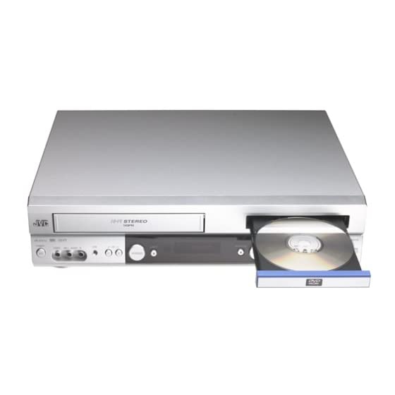
JVC HR-XVC1U Service Manual
Dvd/cd player hi-fi
Hide thumbs
Also See for HR-XVC1U:
- User manual (63 pages) ,
- User manual (20 pages) ,
- User manual (60 pages)
Table of Contents
Advertisement
Quick Links
SERVICE MANUAL
DVD/CD PLAYER Hi-Fi STEREO VIDEO CASETTE RECORDER
TV
POWER
VCR
DVD
DVD MENU
MARKER
RETURN
OPEN/
CLOSE
DISPLAY
A.TRK
C.RESET
ZERO RETURN
SEARCH
SUB TITLE
ANGLE
MODE
SP/EP
PLAY
ZOOM
TITLE
REPEAT
MODE
A-B
TV
POWER
INPUT
TV VOL
0
TIMER
TV/VCR
PLAY
STOP
C
SKIP
SKIP
/INDEX
/INDEX
SET
ENTER/
SET
SELECT
SET UP
MENU
CANCEL
VCR/DVD/TV
SPECIFICATIONS
GENERAL
Power supply:
AC 120V 60Hz
Power consumption:
Operation: 20W
Stand by: 3W
Weight:
9.9lbs (4.5 kg)
Dimensions:
Width : 16-15/16 inches (430 mm)
Height :
Depth : 12-1/4 inches (311 mm)
Inputs/Outputs:
Video:
In: 1Vp-p/75 ohm
Out: 1Vp-p/75 ohm
Audio:
In: -8 dBm/50K ohm
Out: -8 dBm/1K ohm
Antenna:
UHF/VHF IN/OUT: 75 ohm coaxial
Hi-Fi Frequency Response:
20Hz to 20,000Hz
Hi-Fi Dynamic Range:
More than 90dB
VCR section
Video Head:
4 Rotary Heads
Audio Track:
Hi-Fi Sound - 2 Tracks / MONO Sound - 1 Track
Tuner:
181 Channel Freq. Synthesized
VHF
UHF
CATV
RF Channel Output:
Channel 3 or 4, Switchable
F.FWD/REW Time:
Approx. 1minutes and 48 seconds (with T-120 Cassette Tape) (at+25 C)
HR-XVC1U
3-7/8 inches (99 mm)
2-13
14-69
14-36 (A)-(W)
37-59 (AA)-(WW)
60-85 (AAA)-(ZZZ)
86-94 (86)-(94)
95-99 (A-5)-(A-1)
100-125 (100)-(125)
01 (5A)
This service manual is printed on 100% recycled paper.
COPYRIGHT © 2002 VICTOR COMPANY OF JAPAN, LTD
DVD section
Signal system:
NTSC
Applicable disc:
DVD (12cm, 8cm), CD (12cm, 8cm)
Audio characteristics:
DVD: 4Hz - 22KHz
Frequency response:
CD: 4Hz - 20KHz
S/N Ratio:
90dB
Harmonic distortion:
0.01%
Wow and flutter:
Below Measurable Level
Dynamic range:
90dB
Output:
Video :
Audio :
Digital Audio : 0.5Vp-p 75 ohm
Pickup:
CD :
Wavelength: 775 - 805 nm
Maximum output power: 0.5 mW
DVD : Wavelength: 640 - 660 nm
Maximum output power: 1.0 mW
ACCESSORIES:
Remote control x 1
Batteries (2 x AA)
75 ohm Coaxial Cable x 1
AUDIO/VIDEO Cable x 1
(RCA) 1 Vp-p/75ohm
(RCA) -8 dBm/1Kohm
No.82902
January 2002
Advertisement
Table of Contents

Related Manuals for JVC HR-XVC1U


Summary of Contents for JVC HR-XVC1U
-
Page 1: Specifications
SERVICE MANUAL DVD/CD PLAYER Hi-Fi STEREO VIDEO CASETTE RECORDER HR-XVC1U POWER DVD MENU MARKER RETURN OPEN/ CLOSE DISPLAY A.TRK C.RESET ZERO RETURN SEARCH SUB TITLE ANGLE MODE SP/EP PLAY ZOOM TITLE REPEAT MODE POWER INPUT TV VOL TIMER TV/VCR PLAY... -
Page 3: Table Of Contents
BACK TENSION TORQUE DURING PLAY BACK .. 1-20 1-3 CONFIRMATION OF VSR TORQUE ....1-20 1-4 CONFIRMATION OF REEL BRAKE TORQUE ..1-21 The following table lists the differing points between Models (HR-XVC1U and HR-XVC1U(C)) in this series. MODEL HR-XVC1U... -
Page 4: Important Safety Precautions
Important Safety Precautions Prior to shipment from the factory, JVC products are strictly inspected to conform with the recognized product safety and electrical codes of the countries in which they are to be sold. However, in order to maintain such compliance, it is equally important to implement the following precautions when a set is being serviced. - Page 5 Safety Check after Servicing Examine the area surrounding the repaired location for damage or deterioration. Observe that screws, parts and wires have been returned to original positions, Afterwards, perform the following tests and confirm the specified values in order to verify compli- ance with safety standards.
-
Page 6: Servicing Notices On Checking
IMPORTANT WARNING CAUTION: DVD PLAYER IS A CLASS 1 LASER PRODUCT. HOWEVER THIS PLAYER USES A VISIBLE LASER BEAM WHICH COULD CAUSE HAZARDOUS RADIATION EXPOSURE IF DIRECTED. BE SURE TO OPERATE THE PLAYER CORRECTLY AS INSTRUCTED. THE FOLLOWING CAUTION LABEL IS LOCATED ON THE REAR PANEL OF THE PLAYER. CLASS 1 (Printed on the Rear Panel) WHEN THIS PLAYER IS PLUGGED TO THE WALL OUTLET, DO NOT PLACE YOUR EYES CLOSE... -
Page 7: Disassembly Instructions
DISASSEMBLY INSTRUCTIONS REMOVAL OF MECHANICAL PARTS 1-3: VCR DECK (Refer to Fig. 1-3) Unlock the 2 supports 1 and remove the Top Holder. AND P.C. BOARDS Remove the 3 screws 2. 1-1: TOP CABINET AND FRONT CABINET Disconnect the following connectors: (CP101, CP102, (Refer to Fig. -
Page 8: Power Pcb
DISASSEMBLY INSTRUCTIONS 1-5: DECK CD AND MPEG MT PCB (Refer to Fig. 1-5) 1-6: POWER PCB (Refer to Fig. 1-6) Remove the 3 screws 1. Disconnect the following connector: (CP503). Remove the 2 screws 1. Remove the Power PCB in the direction of arrow. Remove the 2 screws 2. -
Page 9: Removal Of Vcr Deck Parts
DISASSEMBLY INSTRUCTIONS NOTE 2. REMOVAL OF VCR DECK PARTS In case of the Locker R installation, check if the two 2-1: TOP BRACKET (Refer to Fig. 2-1) positions of Fig. 2-3-B are correctly locked. Extend the 2 supports 1. When you install the Cassette Side R, be sure to move Slide the 2 supports 2 and remove the Top Bracket. -
Page 10: Loading Motor/Worm
DISASSEMBLY INSTRUCTIONS 2-6: LOADING MOTOR/WORM (Refer to Fig. 2-6-A) Tension Arm Ass’y Remove the screw 1. Remove the Loading Motor. Remove the Worm. Fig. 2-7-A Loading Motor Tension Connect Tension Band Worm Main Chassis Tension Spring Tension Arm Ass’y Tension Holder •... -
Page 11: T Brake Arm/T Brake Band
DISASSEMBLY INSTRUCTIONS 2-8: T BRAKE ARM/T BRAKE BAND (Refer to Fig. 2-8-A) Remove the T Brake Spring. Idler Gear Turn the T Brake Arm clockwise and bend the hook section to remove it. Idler Arm Ass’y Unlock the 2 supports 1 and remove the T Brake Band. S Reel T Brake Band T Reel... -
Page 12: A/C Head
DISASSEMBLY INSTRUCTIONS 2-10: CASSETTE OPENER/PINCH ROLLER BLOCK/P5 ARM ASS’Y (Refer to Fig. 2-10-A) Unlock the support 1 and remove the Cassette Opener. Remove the Pinch Roller Block and P5 Arm Ass’y. Cassette Opener Spring Position Fig. 2-11-B Pinch Roller Block 2-12: FE HEAD (RECORDER ONLY) (Refer to Fig. -
Page 13: Capstan Dd Unit
DISASSEMBLY INSTRUCTIONS 2-14: CAPSTAN DD UNIT (Refer to Fig. 2-14-A) 2-15: MAIN CAM/PINCH ROLLER CAM/JOINT GEAR (Refer to Fig. 2-15-A) Remove the Capstan Belt. Remove the 3 screws 1. Remove the E-Ring 1, then remove the Main Cam. Remove the E-Ring 2, then remove the Pinch Roller Remove the Capstan DD Unit. -
Page 14: Clutch Ass'y/Ring Spring/ Clutch Lever/Clutch Gear
DISASSEMBLY INSTRUCTIONS NOTE 2-18: CASSETTE GUIDE POST/INCLINED BASE S/T UNIT/P4 CAP (Refer to Fig. 2-18-A) 1. When you install the Loading Arm S Unit, Loading Arm T Unit and Main Loading Gear, align each marker. (Refer Remove the P4 Cap. Unlock the support 1 and remove the Cassette Guide to Fig. -
Page 15: Removal And Installation Of Flat Package Ic
DISASSEMBLY INSTRUCTIONS 3. When IC starts moving back and forth easily after 3. REMOVAL AND INSTALLATION OF FLAT desoldering completely, pickup the corner of the IC using PACKAGE IC a tweezers and remove the IC by moving with the IC REMOVAL desoldering machine. -
Page 16: Installation
DISASSEMBLY INSTRUCTIONS INSTALLATION 4. When bridge-soldering between terminals and/or the soldering amount are not enough, resolder using a Thin- 1. Take care of the polarity of new IC and then install the tip Soldering Iron. (Refer to Fig. 4-8.) new IC fitting on the printed circuit pattern. Then solder each lead on the diagonal positions of IC temporarily. -
Page 17: Key To Abbreviations
KEY TO ABBREVIATIONS Audio/Control H.SW Head Switch Automatic Color Control Hertz Audio Erase Integrated Circuit Automatic Frequency Control Intermediate Frequency Automatic Fine Tuning Indicator AFT DET Automatic Fine Tuning Detect Inverter Automatic Gain Control Killer Amplifier Left Antenna Light Emitting Diode A.PB Audio Playback LIMIT AMP... - Page 18 KEY TO ABBREVIATIONS SYNC Synchronization SYNC SEP Sync Separator, Separation Transistor TRAC Tracking TRICK PB Trick Playback Test Point UNREG Unregulated Volt Voltage Controlled Oscillator Video Intermediate Frequency Vertical Pulse, Voltage Display V.PB Video Playback Variable Resistor V.REC Video Recording Visual Search Fast Forward Visual Search Rewind Voltage Super Source...
-
Page 19: Service Mode List
SERVICE MODE LIST This unit provided with the following SERVICE MODES so you can repair, examine and adjust easily. To enter to the SERVICE MODE function, press and hold both buttons simultaneously on the main unit or on the main unit and on the remote control for more than a standard time (second). -
Page 20: When Replacing Eeprom (Memory) Ic
WHEN REPLACING EEPROM (MEMORY) IC If a service repair is undertaken where it has been required to change the MEMORY IC, the following steps should be taken to ensure correct data settings while making reference to TABLE 1. NOTE: No need setting for after INI 2D. Table 1 Connect the set to TV Monitor. -
Page 21: Preventive Checks And Service Intervals
PREVENTIVE CHECKS AND SERVICE INTERVALS The following standard table depends on environmental conditions and usage. Parts replacing time does not mean the life span for individual parts. Also, long term storage or misuse may cause transformation and aging of rubber parts. The following list means standard hours, so the checking hours depends on the conditions. -
Page 22: Cleaning
PREVENTIVE CHECKS AND SERVICE INTERVALS CLEANING NOTE 2. TAPE RUNNING SYSTEM After cleaning the heads with isopropyl alcohol, do not When cleaning the tape transport system, use the gauze run a tape until the heads dry completely. If the heads are moistened with isopropyl alcohol. -
Page 23: Peculuiar Service
PECULUIAR SERVICE 1. DVD SECTION DISC REMOVAL METHOD AT NO POWER SUPPLY 1. Remove the Top Cabinet and Front Cabinet. (Refer to item 1 of the DISASSEMBLY INSTRUCTIONS.) 2. Rotate the white gear of Deck CD section in the direction of the arrow by hand, remove the disc from Deck CD. -
Page 24: Electrical Adjustment Parts Location Guide (Wiring Connection)
ELECTRICAL ADJUSTMENT PARTS LOCATION GUIDE (WIRING CONNECTION) AC IN POWER PCB CP502 CP503 CD503 DECK CD CP101 TP3001 TU301 A/C HEAD TP3002 TP101 CD8002 V651 VCR MT PCB CP681 OPERATION PCB MPEG PCB 1-18... -
Page 25: Vhs Section
PECULUIAR SERVICE 2. VHS SECTION SERVICING FIXTURES AND TOOLS VHS Alignment Tape Torque Gauge Roller Driver X-JG153 X Value Adjustment PUJ48075-2 PTU94002-2 Screwdriver MHP & MHP-L Torque Tape Short Jumper MECHANISM ADJUSTMENT PARTS LOCATION GUIDE 1. Tension Connect P4 Post 2. -
Page 26: Mechanical Adjustments
MECHANICAL ADJUSTMENTS 1. CONFIRMATION AND ADJUSTMENT TAPE REMOVAL METHOD AT Read the following NOTES before starting work. NO POWER SUPPLY • Place an object which weighs between 450g~500g on the Remove the Top Cabinet, Front Cabinet, DVD Block, Power Cassette Tape to keep it steady when you want to make PCB and Center Angle and the Fig. -
Page 27: Confirmation Of Reel Brake Torque
MECHANICAL ADJUSTMENTS 1-4: CONFIRMATION OF REEL BRAKE TORQUE 2. CONFIRMATION AND ADJUSTMENT OF (S Reel Brake) (Refer to Fig. 1-4-B) TAPE RUNNING MECHANISM Once set to the Fast Forward mode then set to the Stop Tape Running Mechanism is adjusted precisely at the mode. -
Page 28: Audio/Control Head
MECHANICAL ADJUSTMENTS 2-2: CONFIRMATION AND ADJUSTMENT OF AUDIO/ 2-3: TAPE RUNNING ADJUSTMENT CONTROL HEAD (X VALUE ADJUSTMENT) When the Tape Running Mechanism does not work well, Confirm and adjust the position of the Tension Post. adjust the following items. (Refer to item 1-1) Adjust the Guide Roller. -
Page 29: Electrical Adjustments
ELECTRICAL ADJUSTMENTS Read and perform this adjustment when repairing the circuits or replacing electrical parts or PCB assemblies. CH-2 1. BASIC ADJUSTMENT 1-1: SWITCHING POINT CONDITIONS 6.5H MODE-PLAYBACK CH-1 Input Signal-Alignment Tape (MHP) Fig. 1-1-A INSTRUCTIONS Connect CH-1 on the oscilloscope to TP3002 and CH-2 to TP8001. -
Page 30: Ic Descriptions
IC DESCRIPTIONS SYSCON PCB OEC0110A (IC3001) PORT PIN NAME DESCRIPTION SVSS SVSS Ground. CTL_REF CTL_REF Output terminal for CTL amp REF (1/2 SVCC) CTL-H(+) CTL-H(+) Input and output terminal of Control Head. CTL-H(-) CTL-H(-) Input terminal of Control Head. CTL_BIAS CTL_BIAS Output terminal for bias. - Page 31 IC DESCRIPTIONS SYSCON PCB OEC0110A (IC3001) PORT PIN NAME DESCRIPTION P13/IRQ3 VIDEO_MUTE H for at AUTO_CLOCK in POWER OFF. L for except above case. P14/IRQ4 POWER_ON_L For control the user power switch ON/OFF. P15/IRQ5 POWER ON-H For control the user power switch ON/OFF. P16/IC REM_IN Receive the remote control signal.
- Page 32 IC DESCRIPTIONS SYSCON PCB OEC0110A (IC3001) PORT PIN NAME DESCRIPTION OSC1 OSC1 Connect the main crystal(10MHz) DVSS Ground. OSC2 OSC2 Connect the main crystal(10MHz) Connect the capacitor FZTAT Write MODE. P34/PWM2 not used. P33/PWM1 CAP_LIMIT Switch the maximum output current of the Capstan Motor. P32/PWM0 T.AUDIO_MUTE H for at PLAY in VCR MODE.
-
Page 33: Servo Timing Chart
SERVO TIMING CHART VCR MT PCB IC3001 (OEC0110A) DPG 104 PIN DFG 104 PIN 24 Cycle CH 1 CH 2 H. SW. P 105 PIN V-SYNC (E-E) 111 PIN REC CTL (REC) 7 PIN V-SYNC (TRICK PB) 109 PIN • WAVEFORM CHANGES DEPENDED ON THE TAPE SPEED 1-27... -
Page 34: Mechanism Timing Chart
MECHANISM TIMING CHART Please see the list below for the operational timing and the mode sensor output of the main parts on each mechanism modes. MECHANISM MODE EJECT STBY UNLOAD STOP3 F.SLOW STOP2 FF/REW Mode Dealing Directions Revolutional Angle of 206.3 226.4 272.2... -
Page 35: Vcr Section
TROUBLESHOOTING CUIDE (VCR SECTION) POWER DOES NOT TURN ON Check pin 13 of T501 Is the voltage at pin 14 Does display light? and peripheral circuit. 5.2V? of CP502 about Check IC3001. Is there voltage at Check Q506,Q504. pin 42 of IC 3001 Check IC3001. - Page 36 TROUBLESHOOTING CUIDE THE POWER SUPPLY CUT Inserting a casette and push play button. Does the power cut Check CAPSTAN DD UNIT after 3 seconds? and CYLINDER UNIT. Does the power cut Check Q3001,Q3002 after about 6 seconds? and CAPSTAN BELT. Check Q3001,Q3002,IC3001 Does intermittently and sag of CAPSTAN BELT.
- Page 37 TROUBLESHOOTING CUIDE AUDIO SHAKES Is AUDIO HEAD Change AUDIO HEAD. scratched? At playback,is input about Change CAPSTAN DD UNIT. 4.5Vp-p of a rectangular wave at pin 9 of IC3001? At playback,is pin 5 of Check IC3001. CP3001 3.5V? Check AUDIO BLOCK. 1-31...
- Page 38 TROUBLESHOOTING CUIDE The CASSETTE TAPE CAN NOT BE INSERTED Does WORM GEAR of Check WORM GEAR cassette loading block of cassette loading block. move? When a CASSETTE can Check LED of DECK, not inserted,is pin 25 of PHOTO SENSOR. IC3001 5V ? When a CASSETTE is Change inserted,is pin 8 of...
- Page 39 TROUBLESHOOTING CUIDE When inserting a CASSETTE, it ejects immediately. Defective CASSETTE Does another CASSETTE or cassette loading insert? block. Does SW3001 and Correctly SW3001 REC LEVER and REC LEVER set. correctly set ? After inserting CASSETTE,is pin 35 Check SW3001. of IC3001 0V ? Check IC3001.
- Page 40 TROUBLESHOOTING CUIDE Can not FF/REW Check line of IC3001 At FF/REW,does voltage at pin29 and pin30. at pin98 of IC3001 change? Check DECK MECHANISM. WHEN PLAYBACK,FF OR REW MODE IS ACTIVE ,UNIT STOPS IMMEDIATELY Refer to section "CAPSTAN Does CAPSTAN DD DD MOTOR NOT MOTOR rotate? ROTAING".
- Page 41 TROUBLESHOOTING CUIDE TAPE loading is ok,but unloads immediately. Is the voltage Does CYLINDER at pin 2 of CP502 Check power block. rotate? 12.6V ? At play,is the voltage at pin 12 of CP3001 2.6V ? Change CYLINDER unit. Is PG PULSE signal Is there HEAD SW inputted to pin 104 PULSE at TP3002...
- Page 42 TROUBLESHOOTING CUIDE At play,the picture jitters vertical minutely Is FG wave of CP3001 Change at pin 11 5V ? CYLINDER MOTOR Change IC3001 Is pin 12 of CP3001 2.6V ? Change CYLINDER MOTOR Auto tracking does not operate Does the CLT pulse signal (about 2.5Vp-p) In auto tracking,is the Check CONTROL HEAD.
- Page 43 TROUBLESHOOTING CUIDE AT PLAY,PICTURE JITTERS HORIZONTALLY Does a noise on the picture appear? By adjusting the MANUAL TRACKING UP/DOWN Check P/B ENVELOPE. BUTTONS,will the line disappear? The height of GUIDE POST Is a height of GUIDE POST readjust maximum? Is PG SHIFTER Adjust PG SHIFTER.
- Page 44 TROUBLESHOOTING CUIDE AT PLAYBACK,THE PICTUER DOES NOT APPEAR Is the voltage of IC101 at Does E-E picture Check POWER BLOCK. pin 44,45,52 and 68 5V? appear? Is there video signal Change IC101 of IC101 at pin 26? Is there video signal Change IC8001 of IC8001 at pin 6? Is there video signal of...
- Page 45 TROUBLESHOOTING CUIDE AT PLAYBACK,THE COLOR DOES NOT APPEAR Is there color signal in Is there video signal at pin Change X'tal video signal at pin 26 of 26 of IC101 IC101 Check pin 19 of IC3001 Change IC101 NO COLOR DURING SELF RECORDING AND PLAYBACK Check TU301,J8003, Is there CHROMA signal at...
- Page 46 TROUBLESHOOTING CUIDE AT PLAYBACK AND RECORDING, CYLINDER MOTOR UNLOAD Check at 12.6V line, Is the voltage at pin 8 of power block. CP3001 about DC12.6V? In playback,is at pin 12 of Check IC3001. CP3001 about DC2.6V? Change CYLINDER MOTOR. PLAYBACK PICTURE IS NOISY (EVEN AFTER CLEANING HEADS) Is noisy a wave of video Check CYLINDER.
- Page 47 TROUBLESHOOTING CUIDE AT PLAY,AUDIO DOES NOT APPEAR Refer to section"E-E DOES At E-E,does audio appear? NOT APPEAR". Check C4024 and around Is the voltage at pin 6 of circuit of it. IC101 about 2.5V? Check circuit around at pin Is there audio signal at pin 10 of IC101.
- Page 48 TROUBLESHOOTING CUIDE THE AUDIO CAN NOT RECORD In starting recording, Check POWER BLOCK and is there sine wave at Is bias level at L101 OK? voltage of base of Q103. pin 7 of IC101? Check disconnection and short of L101. Check IC701 and Is there audio signal at the circuit from TUNER...
- Page 49 TROUBLESHOOTING CUIDE THE CASSETTE INSERT,BUT THE TAPE DOES NOT MOVE Check LOADING MOTOR and Does the mode MODE SENSOR appear at display? RELATION DEPARTMENT. Does operate with Check IC3001. remote control? Check operation PCB. CAPSTAN DD MOTOR NOT ROTATING In playback,is there voltage at Check POWER BLOCK.
- Page 50 TROUBLESHOOTING CUIDE RECORDING MECHANISM WORKS, BUT NO VIDEO RECORD FROM INPUT JACK OR TUNER Check cricuit of video signal from Is there video signal at VIDEO IN or pin 30,32 of IC 3001? TUNER to IC3001. Is the voltage at pin 96 Is the BASE of Change IC3001 of IC3001 5V?
- Page 51 TROUBLESHOOTING CUIDE E-E DOES NOT APPEAR (THE PICTURE DOES NOT APPEAR FROM TUNER) Does normality AUDIO JACK Connection is done over again CONNECT? Are there thevoltage Check POWER BLOCK. of MB(5V),PB(5V), TU(32V) of TU301? Check the picture. Is there video signal at Change TU301.
- Page 52 TROUBLESHOOTING CUIDE E-E AUDIO(MONO) DOES NOT APPEAR Does E-E AUDIO Refer to section "E-E AUDIO (STEREO) DOES NOT APPEAR". (STEREO) appear? Is the voltage at pin 7 Check POWER BLOCK. of IC101 5V? Is the voltage at pin 95 of Change IC301.
- Page 53 TROUBLESHOOTING CUIDE E-E AUDIO(STEREO) DOES NOT APPEAR Is the voltage at pin Check POWER BLOCK. 25,40,51 of IC701 5V? Is the voltage at pin Check POWER BLOCK. 58 of IC701 12V? Is there video signal at Change IC101. pin 10,15 of IC701? Is there video signal at Change IC701.
- Page 54 TROUBLESHOOTING CUIDE TUNER AUDIO(MONO) DOES NOT APPEAR Does E-E AUDIO Refer to section "E-E AUDIO (MONO) DOES NOT APPEAR". (MONO) appear? Check circuit around of TU301 Is there video signal at pin 22. at pin 48 of IC701? Is there audio signal at Change IC701.
- Page 55 TROUBLESHOOTING CUIDE TUNER AUDIO(STEREO) DOES NOT APPEAR Does TUNER AUDIO Refer to section "TUNER AUDIO (MONO) DOES NOT APPEAR". (MONO) appear? Does E-E AUDIO Refer to section "E-E AUDIO (STEREO) DOES NOT APPEAR". (STEREO) appear? At the time of channel Change IC701.
- Page 56 TROUBLESHOOTING CUIDE PB AUDIO(Hi-Fi) DOES NOT APPEAR Does E-E AUDIO Refer to section "E-E AUDIO (STEREO) appear? (STEREO) DOES NOT APPEAR". Refer to section "AT PLAY, Does NORMAL PB AUDIO DOES NOT APPEAR". AUDIO appear? Check circuit of HEAD AMP Is there audio signal at and CYLINDER UNIT.
- Page 57 TROUBLESHOOTING CUIDE Hi-Fi AUDIO CAN NOT RECORD Refer to section "E-E AUDIO Does E-E AUDIO appear? (MONO) DOES NOT APPEAR". AT state of video recording, Check circuit arounf of is there audio signal at J8004,J8005 and TU301. pin 10 and 15 of IC701? Is there audio signal at Change IC701.
-
Page 58: Dvd Section
TROUBLESHOOTING CUIDE (DVD SECTION) Deck does not accept open/close Is the DVD Is CD503 connected CD503 is connected again display out ? correctly ? Confirmation of the MPEG PCB (P.CON 5V,P.CON 9V,P.CON 5V D) Can it open and close Change DECK CD it manually? (*1) "DVD mode unstable"... - Page 59 TROUBLESHOOTING CUIDE DVD screen without going out Are CD4001,CD4002 CD4001,CD4002 are connected correctly ? connected again Connector on the side of DECK CD is not Change DECK CD turning or short Change X1001 Is X1001 oscillating? Are there signals at pins Change IC8501 24,25 of IC8501 Change IC4001...
- Page 60 TROUBLESHOOTING CUIDE Do not playback DVD Does display "Incorrect Is CD4001 connected Change DECK CD Disc" after reading ? correctly ? CD4001 is connected again When it playback dvd disc Change DECK CD as for SPINDLE MOTOR is it revolve ? Are there output signals Check IC8001 and at pins 57,58,59 of...
- Page 61 TROUBLESHOOTING CUIDE DVD mode unstable Is CD4001 connected CD4001 is connected again correctly ? Connector on the side of Change DECK CD DECK CD is not turning or short Are CD8002, CD8501 CD8002,CD8501 are connected again connected correctly ? Change DECK CD 1-55...
- Page 62 TROUBLESHOOTING CUIDE Do not playback CD As for the motor is it Change DECK CD revolve at the time of reading ? Connector on the side of DECK CD is not Change DECK CD turning or short Are there input signals Check connection of CP4002 at pin 3,4,5,6 of IC4001 and peripheral circuit...
- Page 63 TROUBLESHOOTING CUIDE No digital audio on playback Is there waveform Check OS8001 and peripheral at pin 3 of IC8504 ? circuit of J8007 Are there audio signals at Change IC8504 pin 1,4 of IC8504 ? Is there audio waveform Check peripheral circuit of at pin 117 of IC4001 ? IC8504 Is there waveform...
- Page 64 TROUBLESHOOTING CUIDE DVD/CD ANLOG AUDIO DOES NOT APPEAR Is there audio waveform at pin 3,5 of Check circuit around of J8001. IC8001? Is there audio waveform Change IC8504. at pin 1,14 of IC8504? Is there audio waveform Check circuit around of IC8007. at pin 3,14 of IC8007? Is there audio Change IC8007.
- Page 65 TROUBLESHOOTING CUIDE NO PLAYBACK PICTURE OF Y.U.V OUT Is there Y.U.V Is there Y.U.V waveform at waveform at pin 7,9 Check circuit around of J8008. pin 42,43,44 of IC8501? and 11 of CP8502? Check circuit around of D8504,D8508 and D8512. Are there signals at pins Check circuit around of IC8501 13,14,15,16,19,20...
- Page 66 TROUBLESHOOTING CUIDE No playback picture of S-VIDEO jack Are there Y signal at pin 59 Check D8506 and circuit and C signal at pin 58 of around of D8510 IC8501 ? Are there waveform at pins 13~16,19~22 Change IC8501 of IC8501 ? Are there waveform at Check IC8501 and circuit pins 92,94~97,99~...
- Page 67 <Reference> <Reference> GENERAL SPECIFICATIONS [HR-XVC1U] Outline of the product DVD VIDEO PLAYER & VHS Player / Recorder DVD System Color System NTSC Disc DVD, CD-DA, CD-R/RW, VIDEO CD Disc Diameter 120 mm , 80 mm Deck Disc Loading System Front Disc Loding...
- Page 68 <Reference> GENERAL SPECIFICATIONS [HR-XVC1U] Temperature Operation 5C - 40C Storage -20C - 60C Operating Humidity Less then 80% RH Signal Video Signal Output Level 1 V p-p/75 ohm (DVD,VCR) S/N Ratio (Weighted) 65 dB(DVD) 50 dB(VCR) Horizontal Resolution 500 Lines (DVD)
- Page 69 <Reference> GENERAL SPECIFICATIONS [HR-XVC1U] On Screen Menu Display(VCR) Menu Type Character Timer Rec Set Auto Repeat On/Off SAP On/Off Surround On/Off CH Set-Up TV/CATV Auto CH Memory Add/Delete System Set Up Clock Set Yes (Calendar 12H) Language No Noise Back Ground...
- Page 70 <Reference> GENERAL SPECIFICATIONS [HR-XVC1U] G-14 Remote Unit RC-FB Control Glow in Dark Remocon Format Custom Code 43,53(DVD,VCR), 03(TV) Power Source Voltage(D.C) UM size x pcs UM-3 x 2 pcs Total Keys 50 Key Keys Power DISPLAY/CALL Input Select UP/CH+- DOWN/CH-...
- Page 71 <Reference> GENERAL SPECIFICATIONS [HR-XVC1U] G-15 Features Auto Power Off (DVD) Parental Lock Echo Mic Mixing Video CD Playback MP3 Playback Digital Out Dolby Digtal Down Mix Out (Dolby Digtal) Self Diagnostic Features Auto Head Cleaning (VCR) Auto Tracking HQ (VHS Standard High Quality)
- Page 72 <Reference> GENERAL SPECIFICATIONS [HR-XVC1U] G-17 Interface Switch Front Power Play Eject (VCR) Stop Rec/OTR Open/Close (DVD) CH + CH - FF/ Search(>>) Rew/Search(<<) Still/Pause Shuttle(Search/REV/FWD) DVD/VCR Main Power SW Rear Attenuator Video/RGB Selector RF Out(Slide SW) Yes (3ch/4ch) Main Power SW...
- Page 74 JVC SERVICE & ENGINEERING COMPANY OF AMERICA DIVISION OF JVC AMERICAS CORP. Head office 1700 Valley Road Wayne, New Jersey 07470-9976 (973)317-5000 East Coast 10 New Maple Avenue Pine Brook, New Jersey 07058-9641 (973)396-1000 705 Enterprise Street Aurora, Illinois 60504-8149...
- Page 75 PAD,DVD/VR X-JB5KD200 POLY BAG PEAC0294-03 CABLE X-J2A30201 INSTRUCTION BOOK QAM0174-001 CORD,RCA PIN X-J2A30401 INSTRUCTION BOOK,HR-XVC1U(C) X-076D0FB010 TRANSMITTER X-J5500117 REGISTRATION CARD,HR-XVC1U X-791WHA0100 GIFT SHEET X-J5500112 GUARANTEE CARD,HR-XVC1U(C) X-792WHA0344 PACKAGE X-J5500115 SERVICE STATION LIST,HR-XVC1U(C) X-792WHA0345 PACKAGE,PAD TOP -------- BATTERY,X2 X-792WHA0346 PACKAGE,PAD UNDER...
-
Page 76: Final Assembly
FINAL ASSEMBLY <M2> BEWARE OF BOGUS PARTS Parts that do not meet specifications may cause trouble in regard to safety and per- formance. We recommend that genuine JVC parts be used. DK4001 TU301 PCB010 (VCR MT PCB) PCB120 (MPEG MT PCB) - Page 77 REF No. PART No. PART NAME, DESCRIPTION REF No. PART No. PART NAME, DESCRIPTION - - - - - - - - - - - - - - - - - - - - - - - - - - - - - - - - - - - - - - - - - - - - - - - - - - - - - - - - - - - - - - - - - - - - - - - - - - - - - - - - - - - - - - - - - - - - - - - - - - - - - - - - - - - - - - - - - - - - - - - - - - - - - - - - - -...
- Page 78 < > MECHANISM ASSEMBLY [ TOP VIEW ] M2003 UN4001 H5002 H5001 M101 NOTE: Applying positions AA, AB, AC and AD for the CLASS PART NO. MARK grease are displayed for this section. GREASE G-555G Check if the correct grease is applied for each MG-33 position.
- Page 79 [ BOTTOM VIEW ] CD1501 M2001 CD1502 NOTE: Applying positions AA, AB, AC and AD for the CLASS PART NO. MARK grease are displayed for this section. GREASE G-555G Check if the correct grease is applied for each MG-33 position. FG-84M FL-721...
- Page 80 REF No. PART No. PART NAME, DESCRIPTION REF No. PART No. PART NAME, DESCRIPTION - - - - - - - - - - - - - - - - - - - - - - - - - - - - - - - - - - - - - - - - - - - - - - - - - - - - - - - - - - - - - - - - - - - - - - - - - - - - - - - - - - - - - - - - - - - - - - - - - - - - - - - - - - - - - - - - - - - - - - - - - - - - - - - - - -...
- Page 81 ELECTRICAL PARTS LIST REF No. PART No. PART NAME, DESCRIPTION REF No. PART No. PART NAME, DESCRIPTION - - - - - - - - - - - - - - - - - - - - - - - - - - - - - - - - - - - - - - - - - - - - - - - - - - - - - - - - - - - - - - - - - - - - - - - - - - - - - - - - - - - - - - - - - - - - - - - - - - - - - - - - - - - - - - - - - - - - - - - - - - - - - - - - - -...
- Page 82 REF No. PART No. PART NAME, DESCRIPTION REF No. PART No. PART NAME, DESCRIPTION - - - - - - - - - - - - - - - - - - - - - - - - - - - - - - - - - - - - - - - - - - - - - - - - - - - - - - - - - - - - - - - - - - - - - - - - - - - - - - - - - - - - - - - - - - - - - - - - - - - - - - - - - - - - - - - - - - - - - - - - - - - - - - - - - -...
- Page 83 REF No. PART No. PART NAME, DESCRIPTION REF No. PART No. PART NAME, DESCRIPTION - - - - - - - - - - - - - - - - - - - - - - - - - - - - - - - - - - - - - - - - - - - - - - - - - - - - - - - - - - - - - - - - - - - - - - - - - - - - - - - - - - - - - - - - - - - - - - - - - - - - - - - - - - - - - - - - - - - - - - - - - - - - - - - - - -...
- Page 84 REF No. PART No. PART NAME, DESCRIPTION REF No. PART No. PART NAME, DESCRIPTION - - - - - - - - - - - - - - - - - - - - - - - - - - - - - - - - - - - - - - - - - - - - - - - - - - - - - - - - - - - - - - - - - - - - - - - - - - - - - - - - - - - - - - - - - - - - - - - - - - - - - - - - - - - - - - - - - - - - - - - - - - - - - - - - - -...
-
Page 85: Mpeg Mt Pcb Assembly <50>
REF No. PART No. PART NAME, DESCRIPTION REF No. PART No. PART NAME, DESCRIPTION - - - - - - - - - - - - - - - - - - - - - - - - - - - - - - - - - - - - - - - - - - - - - - - - - - - - - - - - - - - - - - - - - - - - - - - - - - - - - - - - - - - - - - - - - - - - - - - - - - - - - - - - - - - - - - - - - - - - - - - - - - - - - - - - - -... - Page 86 REF No. PART No. PART NAME, DESCRIPTION REF No. PART No. PART NAME, DESCRIPTION - - - - - - - - - - - - - - - - - - - - - - - - - - - - - - - - - - - - - - - - - - - - - - - - - - - - - - - - - - - - - - - - - - - - - - - - - - - - - - - - - - - - - - - - - - - - - - - - - - - - - - - - - - - - - - - - - - - - - - - - - - - - - - - - - -...
-
Page 87: Power Pcb Assembly <01>
REF No. PART No. PART NAME, DESCRIPTION REF No. PART No. PART NAME, DESCRIPTION - - - - - - - - - - - - - - - - - - - - - - - - - - - - - - - - - - - - - - - - - - - - - - - - - - - - - - - - - - - - - - - - - - - - - - - - - - - - - - - - - - - - - - - - - - - - - - - - - - - - - - - - - - - - - - - - - - - - - - - - - - - - - - - - - -... -
Page 88: Operation Pcb Assembly <28>
X-0021E5Q210 LTL-1CHGE-002A SW681 X-0504201T32 TACT SWITCH SKQNAED010 SW682 X-0504201T32 TACT SWITCH SKQNAED010 SW684 X-0504201T32 TACT SWITCH SKQNAED010 SW686 X-0504201T32 TACT SWITCH SKQNAED010 SW688 X-0504201T32 TACT SWITCH SKQNAED010 SW689 X-0504201T32 TACT SWITCH SKQNAED010 CP681 X-069R750499 CONNECTOR PCB SIDE HR-XVC1U/U(C) (VP)-V14PV1 3-14... -
Page 89: Interconnection Diagram
SECTION 2 CHARTS AND DIAGRAMS INTERCONNECTION DIAGRAM OPERATION PCB PCB270 VEA970 COMMAND TRANSMITTER TM601 CP4001 CD4001 FULL ERASE HEAD ASSíY SDT7 SDT7 DRIVE SDT6 SDT6 HALL MAIN ROTOR SENSOR COIL MAGNET FG SENSOR SDT5 SDT5 SDT4 SDT4 MPEG PCB PCB120 OS651 VMA236 SDT3... -
Page 90: Power Schematic Diagram
POWER SCHEMATIC DIAGRAM (POWER PCB) T501_1 81290814 L501_1 0R7A223F24 D506 RM11C-EIC D503 L507 139.3 D515 W804 RM11C-EIC SB340L-6737 22uH TSL0808 142.0 D502 S502 RM11C-EIC WHITE F501_1 W813 4A125V S501 B503 D505 C516 BLACK W4BRH3.5X6X1 D518 R536 AC120V_60HZ RM11C-EIC 250V 0.0047 1SS133 1K 1/4W CD501_4... -
Page 91: Mpeg Schematic Diagram
MPEG SCHEMATIC DIAGRAM (MPEG PCB) FROM/TO LOADER R4001_2 B4003 CP4001 HCB2012K-600T25 CD4001 IMSA-9615S-26C-P DVDDAT7 SDT7 C4007 C4012 C4008 2S0Q0901 0.001 B 5P CH DVDDAT6 SDT6 FROM/TO VIDEO ENCODER DVDDAT5 SDT5 DVDDAT4 SDT4 DGND P.CON+3.3VB DVDDAT3 R4029 SDT3 CLK27 C4017 C4015 DVDDAT2 SDT2 B4001... -
Page 92: Sdram Schematic Diagram
SDRAM SCHEMATIC DIAGRAM (MPEG PCB) FROM/TO MPEG S-DRAM IC4002 HY57V161610DTC-8 MD15 I/O15 I/O0 MD14 MA10 I/O14 I/O1 MA11 MCS0# VSSQ VSSQ MRAS# MPCLK MD13 MCAS# I/O13 I/O2 MWE# MDQM MD12 I/O12 I/O3 VCCQ VCCQ MD10 MD11 MD11 I/O11 I/O4 MD12 MD10 I/O10 I/O5... -
Page 93: Dvd Syscon Schematic Diagram
DVD SYSCON SCHEMATIC DIAGRAM (MPEG PCB) JG1012 FROM/TO VIDEO ENCODER B1001 JG1011 DVD_RESET HCB2012K-600T25 MUTE MICON+3.3V JG1013 P.CON+D5V DGND RESET EEPROM IC1006 BR24C01AF-WE2 CD/DVD TEST R1004 4.7K R1005 R1034 NC NC NC NC NC NC NC NC NC NC NC NC NC NC 4.7K 4.7K FROM/TO MPEG... -
Page 94: Video Encorder Schematic Diagram
VIDEO ENCORDER SCHEMATIC DIAGRAM (MPEG PCB) FROM/TO MPEG DGND P.CON+3.3VB L8507 P.CON+3.3V FROM/TO DVD I/O W5T29X7.5X19 CD8501 AMCLK CU2D2501 CLK27 ABCLK ALRCLK 0 3.2 SPDIF-DVD ASDAT0 YUV0 VID2 AGND YUV1 P.CON3.3V(MICON) YUV2 YUV3 VID3 DACA P.CON3.3V(PLL) YUV4 61 GND P.CON+D5V YUV5 VID4 VID1... -
Page 95: Y/C Audio/Ccd/Head Amp Schematic Diagram
Y/C/AUDIO/CCD/HEAD AMP SCHEMATIC DIAGRAM (VCR PCB) FROM/TO DVD I/O DVD_V_OUT R129 BUFFER Q109 1.8K 2SC2412K 1/4W FROM/TO REGULATOR P.CON+5V FROM/TO TUNER/JACK C142 FRONT_V_IN TU/REAR_V_IN C143 Y/C_VIDEO_OUT 0.1 F R127 C141 FROM/TO HI-FI/DEMODULATOR 680K 0.01 B TO_NORMAL_A FROM_NORMAL_A HF_COM BUFFER C166 COMP ALWAYS 4Fsc... -
Page 96: Vcr Syscon Schematic Diagram
VCR SYSCON SCHEMATIC DIAGRAM (VCR PCB) AT+5V[M-CON] TP3002 H.SW AT+5.2V FROM/TO REGULATOR FROM/TO Y/C/AUDIO/CCD/H.AMP CAP_VCO C3025 C3047 AT+12.6_V 18P CH DUMMY_V.SYNC 15P CH P.CON+5V C.SYNC AT+5.2V X3001 V.REC_ST-H AT+5V[M-CON] 10MHz C.ROTARY VCR_POWER_ON-H R3034 AUDIO_MUTE-H VCR_POWER_ON-L CTL- POWER_FAIL CTL+ H.AMP_SW C3061 R3057 MOTOR_GND CAP_LIMIT... -
Page 97: Tuner/Jack Schematic Diagram
TUNER/JACK SCHEMATIC DIAGRAM (VCR PCB) COMPONENT OUT DVD AUDIO OUT REAR OUT JACK J8008 J8009 MSP-213V1-652_PBSN J8001 MSP-213V1-432_PBSN MSP-242V2-01PBSN RF-SW OPT TRNSFORMER SW301 OS8001 GP1FA550TZ SLD-12-592 D AUDIO FROM/TO DVD I/O TU301 DRIVER C8037 R8028 TCMN0682PA13D(4) Q8001 Y/C SEPA DVD_Y 2SA1037AK L8001 C8010... -
Page 98: Regulator Schematic Diagram
REGULATOR SCHEMATIC DIAGRAM (VCR PCB) W804 CAP_VCO R1716 D1709 2.2K 1/4W AT+12.6_V 1N4005-EIC MOTOR_GND AT+5.2V AT+5.2V FROM/TO HI-FI/DEMODULATOR P.CON+5V P.CON+5V SW Q1702 P.CON+12V KTC3209_Y R1703 P.CON+5V P.CON+12V 220 1/2W P.CON+5V_DH P.CON+5V SW Q1703 AT+5V[M-CON] KTC3209_Y R1714 M-CON +5V SW Q1713 KTA1271_Y 390 1/4W 3.3V OUT Q1706... -
Page 99: Operation/Display Schematic Diagram
OPERATION/DISPLAY SCHEMATIC DIAGRAM (VCR PCB) V651 ELF-4M6SDRSOWB SEG1 SW Q664 KRC103SRTK FROM/TO VCR SYSCON R674 1G SW DVD_LED Q665 2SA1037AK VCR_LED 1G/VCR/T-REC_LED SEG2 SW 2G/DUB/REC_LED Q663 3G/TV/VCR_LED KRC103SRTK R673 4G/T_SHT_LED 5G/CS/BS_LED SEG3 SW SEG10 SW Q662 Q652 SEG_1 KRC103SRTK KRC103SRTK SEG_2 R672 R662... -
Page 100: Hi-Fi/Demodulator Schematic Diagram
HI-FI/DEMODULATOR SCHEMATIC DIAGRAM (VCR PCB) C744 0.1 F C743 R716 3.3K 0.22 FROM/TO TUNER/JACK FRONT_A_IN_R FRONT_A_IN_L HIFI_A_OUT_L HIFI_A_OUT_R HI-FI/AUDIO/HEAD AMP/DEM IC R717 RF_CONV_A_OUT IC701 AN3663FBP SIF_OUT 2.2M C746 C730 0.015 B DEM_BLK ZZ-PROM LOGIC C747 C731 C751 4.5M 95HMz MUTE VCO-F0 TRAP DEMOD HIFI ENV. -
Page 101: Dvd In/Out Schematic Diagram
DVD IN/OUT SCHEMATIC DIAGRAM (VCR PCB) FROM/TO VIDEO ENCODER CP8001 (CD8501) A2001WV2-13P W805 W802 W814 P.CON3.3V(MICON) W815 P.CON3.3V(PLL) P.CON+5V_DH P.CON+D5V C8048 P.CON+D5V 6.3V P.CON+3.3V P.CON+3.3V P.CON+3.3V W816 SPDIF-134 SPDIF-134 FROM/TO TUNER/JACK Y_OUT C_OUT SPDIF-134 DVD_Y DVD_U DVD_V DVD_A_OUT_L DVD_A_OUT_R DVD_V_OUT DVD_MUTE_L DVD_MUTE_R FROM/TO VIDEO ENCODER... -
Page 102: Operation Schematic Diagram
OPERATION SCHEMATIC DIAGRAM (OPERATION PCB) R681 R683 R685 R687 R688 13K1/4W 6.8K 1/4W 3.9K 1/4W 2.7K 1/4W 3.3K 1/4W DVD LED D681_1 R690 5601/4W LTL-1CHGE-002A R689 10K1/4W FROM/TO OPERATION/DISPLAY CP681_1 (CP651) 52492-0520 DVD LED KEY-A KEY-B PCB270 VEA970 NOTE: THIS SCHEMATIC DIAGRAM IS THE LATEST AT THE TIME NOTE: THE DC VOLTAGE AT EACH PART WAS OF PRINTING AND SUBJECT TO CHANGE WITHOUT NOTICE... -
Page 103: Printed Circuit Boards Power/Operation
PRINTED CIRCUIT BOARDS PRINTED CIRCUIT BOARDS PRINTED CIRCUIT BOARDS POWER/OPERATION POWER/OPERATION SOLDER SIDE SOLDER SIDE MPEG (TOP SIDE) CAUTION : FOR CONTINUED PROTECTION AGAINST FIRE HAZARD, REPLACE ONLY WITH SAME TYPE AND RATED FUSE(S). FOR CONTINUED PROTECTION AGAINST FIRE HAZARD, REPLACE ONLY WITH SAME TYPE CP(S) MANUFACTURED BY ROHM. CD8501 ATTENTION : REPLACER PAR DES FUSIBLE DE MEME TYPE. -
Page 104: Vcr
PRINTED CIRCUIT BOARDS VCR (INSERTED PARTS) SOLDER SIDE CP651 CP8002 CP8001 W814 CP1701_1 W111 W167 W250 W816 W240 W815 W203 W252 W238 C8106 C8023 W248 W254 D1709 R1706 Q1702 Q1703 Q1706 R1709 W025 R1714 W205 Q3004 W053 R1720 W235 Q1713 W123 W257 W124... - Page 105 COMPONENT PARTS LOCATION GUIDE <VCR MT> VMA237A PRINTED CIRCUIT BOARDS REF.NO. LOCATION REF.NO. LOCATION REF.NO. LOCATION REF.NO. LOCATION REF.NO. LOCATION REF VCR (CHIP MOUNTED PARTS) CAPASITOR C713 D8013 R132 R8016 C103 C714 D8014 R133 R8017 SOLDER SIDE C104 C715 D8015 R136 R8019 C105...
-
Page 106: Waveforms
WAVEFORMS WAVEFORMS MPEG Y/C/AUDIO/CCD/HEAD AMP VCR SYSCON 10µs 10µs 500mV 50ns 500mV 1.0V 1.0V SDRAM 10µs 100ns 200µs 500mV 100mV 1.0V 2.0V HIFI/DEMODULATOR 10µs 50ns 10ms 500mV 100mV 1.0V 1.0V DVD SYSCON VIDEO ENCODER 200ms 500µs 10µs 500mV 1.0V 200mV 10µs 500mV TUNER/JACK... - Page 107 WAVEFORMS SOUND AMP 10µs 200mV 10µs 200mV POWER 10µs 5µs 200mV 500mV 500ns 5µs 100mV 5.0V 500ns 1.0V NOTE: The following waveforms were measured at the point of the corresponding balloon number in the schematic diagram. 2-37 2-38...
-
Page 108: Dvd Block Diagram
DVD BLOCK DIAGRAM AUDIO SW FROM/TO VIDEO BLOCK IC8504 SN74LV4052APW SPDIF(CD) DVD REQ SPDIF-134 SPDIF(DVD) DVD ROM DRIVE DVD ERR,DVD SOS,DVD VALID,DVD STB DVD: "L" DVD/CD KIT515SE CD : "H" ZERO DVD DATA (0-7) AUDIO DAC ANALOGUE IC8503 AUDIO OUT CD DATA (ERR, FRM, DAT, CLK) PCM1748E X4001... -
Page 109: Y/C/Audio/Ccd/Head Amp Block Diagram
Y/C/AUDIO/CCD/HEAD MAP BLOCK DIAGRAM AUDIO SIGNAL(REC) X101 AUDIO SIGNAL (PB) 3.578545M Hz PLAYBACK COLOR SIGNAL PLAYBACK LUMINANCE SIGNAL RECORD COLOR SIGNAL Q109 RECORD LUMINANCE SIGNAL Q107 TUNER VIDEO SIGNAL BUFFER Y/C/AUDIO/CCD/HEAD AMP IC BUFFER IC101 LA71205M-MPB VX01 PULL Y/C_CS SERIAL SYSCON TIMMING DRIVER... -
Page 110: System Control Block Diagram
SYSTEM CONTROL BLOCK DIAGRAM PLAYBACK COLOR SIGNAL PLAYBACK LUMINANCE SIGNAL RECORD COLOR SIGNAL V.REC_ST-H SYSCON/TIMER/SERVO RECORD LUMINANCE SIGNAL IC1001 OEC0110A AUDIO_MUTE-H IIC_CLK HIFI/ VCR_POWER_ON-H HEATER SW IIC_DATA DEMODULATOR REGULATOR VCR_POWER_ON-L POWER ON-L HIFI ENV 32 HIFI_ENV.DET POWER_FAIL POWER FAIL HIFI H.SW 106 HIFI_H.SW ST SELECT 31 ST_SELECT... -
Page 111: Regulator Block Diagram
REGULATOR BLOCK DIAGRAM CAP_VOC AT+5V AT+12.6V MOTOR_GND SYSCON AT+5.2V Q1702 P.CON 5V SW. P.CON+5V Q1703 P.CON 5V SW. Q1713 M-CON AT 5V SW. AT+5.2V OPERATION/ DISPLAY Q1714 M-CON POWER P.CON+12V HIFI/DEMODULATOR P.CON+5V CP1701 MOTOR +12V P.CON+5V Y/C/AUDIO/CCD/ MOTOR GND Q1701 HEAD MAP AT +13V P.CON 12V SW. -
Page 112: Operation/Display Block Diagram
OPERATION/DISPLAY BLOCK DIAGRAM V651 ELF-4M6SDRVGWB 14 15 13 12 11 10 8 Q651 5G/CS/BS_LED 5G SW Q652 SEG10 SW SEG10 Q653 SEG9 SW SEG9 Q654 4G SW 4G/T_SHT_LED Q655 SEG8 SW SEG8 Q656 SEG7 SEG7 SW Q657 SEG6 SW SEG6 Q658 SYSCON SEG5 SW... -
Page 113: Hifi/Demodulator Block Diagram
HIFI/DEMODULATOR BLOCK DIAGRM HIFI AUDIO/H.AMP/DEM IC IC701 AN3672NFBP DVD_A_OUT-R DVD I/O DVD_A_OUT- FRONT_A_IN-R FRONT_A_IN-L INPUT SW HIFI AUDIO_OUT_R HF_COM OUTPUT HIIFI AUDIO_OUT_L RF_CONV_A.OUT TUNER/JACK Y/C/AUDIO/CCD /HEAD AMP VCO-FO LOGIC SIF OUT FM LIM FROM_NORMAL_A TO_NORMAL_A NOISE BLOCK REDUCTION V. REC_ST-H HIFI_ENV. -
Page 114: Tuner/Jack Block Diagram
TUNER/JACK BLOCK DIAGRAM COAXAL DIGITAL OUT OPT TRANSSFORMER J8007 OS8001 COMPONENT OUT FRONT AV JACK J8008 VIDEO AUDIO L DVD AUDIO OUT REAR OUT JACK AUDIO R Y/C SEPA Q8001 J8003 J8004 J8009 J8001 J8005 J8006 D.AUDIO DRIVER VIDEO MUTE H Q8004 SYSCON DVD_Y... -
Page 115: Dvd In/Out Block Diagram
DVD IN/OUT BLOCK DIAGRAM CD8001 SYSCON DVD RESET PCON+3.3VA PCON+3.3VA FROM/TO PCON+5V DVD BLOCK PCON+5V P.CON +5V DH REGULATOR PCON+3.3V P.CON+3.3V PCON+3.3V ZERO SYS_MUTE SPDIF-134 SPDIF-134 Y_OUT TUNER/JACK C_OUT CP8002 DVD_V_OUT DVD_U DVD_V DVD_Y DVD_A_OUT-L CVBS DVD_A_OUT-R DVD U FROM/TO Y/C/AUDIO/CCD/ DVD_V_OUT DVD BLOCK... - Page 116 IC502 KIA7809API D505, D506 D502, D503 Q501 P.CON5V IC501 Q501 MM1431ATT P.CON+B VOLTAGE CTL. IC Q506 Q501 Q502 Q503 PHOTO P.CON SW. CONTROL COUPLER L501 AC IN CP503 P.CON+5V D P.CON+5V A P.CON+9V A MOTOR GND HR-XVC1U/U(C) (VP)-V14PV1 2-55 2-56...