Uniclass DX120 User Manual
Kvm matrix over ip
extender system
Hide thumbs
Also See for DX120:
- Quick installation manual (3 pages) ,
- Quick installation manual (2 pages)
Table of Contents
Advertisement
Advertisement
Table of Contents

Subscribe to Our Youtube Channel
Related Manuals for Uniclass DX120


Summary of Contents for Uniclass DX120
- Page 1 User's Manual KVM Matrix over IP Extender System Version : 0.32...
-
Page 2: Table Of Contents
Introduction ......................3 Connection diagram ....................3 DX120........................4 Specifications .......................4 Features ........................4 Parts overivew.......................5 DX220........................7 Specifications .......................7 Features ........................7 Parts overivew.......................8 VX120 ........................10 Specifications ........................10 Features ........................10 Parts overivew.......................11 VX220 ........................13 Specifications ........................13 Features ........................13 Parts overivew.......................14 Pre-Installation ...................... -
Page 3: Introduction
Thanks for purchasing KVM Matrix over IP Extender System. With our highly reliable and quality product, you can enjoy countless benefits by using this device. Introduction KVM Matrix over IP Extender System is designed to extend computers to consoles by combing multiple transmitters and receivers. -
Page 4: Dx120
DX120 Specifications Model No. DX120-TX DX120-RX Component Units 1 x DX120-TX(Transmitter Unit) 1 x DX120-RX(Receiver Unit) PC Connections Connectors 1 x DVI-D Female 1 x DVI-D Female 1 x Remote Out Jack 1 x Remote In Jack 1 x USB Port (Type B) 4 x USB Port (Type A) 1 x Mic. -
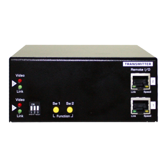
Page 5: Parts Overivew
Parts overivew Transmitter 1 2 3 6 7 8 ON DIP 1 2 3 4 No. Item Description 1 Reset button Reset the unit. 2 Power LED Lights up when the power is on. 3 Link LED Lights up when the link is active. 4 Momentary switch (Sw1) Short press to switch on or off the remote console. - Page 6 Receiver 1 2 3 8 9 10 No. Item Description 1 Reset button Reset the unit. 2 Power LED Lights up when the power is on. 3 Link LED Lights up when the link is active. 4 Momentary switch (Sw1) Short press to switch on or off the remote console. 5 Momentary switch (Sw2) •...
-
Page 7: Dx220
DX220 Specifications Model No. DX220-TX DX220-RX Component Units 1 x DX120-TX(Transmitter Unit) 1 x DX120-RX(Receiver Unit) PC Connections Connectors 2 x DVI-D Female 2 x DVI-D Female 1 x Remote Out Jack 1 x Remote In Jack 1 x USB Port (Type B) 4 x USB Port (Type A) 1 x Mic. -
Page 8: Parts Overivew
Parts overivew Transmitter 15 16 17 1 2 3 6 7 8 ON DIP 1 2 3 4 No. Item Description 1 Reset button Reset the unit. 2 Video LED 1 Lights up when the power is on. 3 Link LED 1 Lights up when the link is active. - Page 9 Receiver 1 2 3 8 9 10 17 18 No. Item Description 1 Reset button Reset the unit. 2 Video LED 1 Lights up when the power is on. 3 Link LED 1 Lights up when the link is active. 4 Momentary switch (Sw1) Short press to switch on or off the remote console.
-
Page 10: Vx120
VX120 Specifications Model No. VX120-TX VX120-RX Component Units 1 x VX120-TX(Transmitter Unit) 1 x VX120-RX(Receiver Unit) PC Connections Connectors 1 x HDB15 Female 1 x HDB15 Female 1 x Remote Out Jack 1 x Remote In Jack 1 x USB Port (Type B) 4 x USB Port (Type A) 1 x Mic. -
Page 11: Parts Overivew
Parts overivew Transmitter ON DIP 1 2 3 4 6 7 8 No. Item Description 1 Power LED Lights up when the power is on. 2 Link LED Lights up when the link is active. 3 Four position dip switch Change the channel of Transmitter. 4 Momentary switch (Sw1) Short press to switch on or off the remote console. - Page 12 Receiver ON DIP 1 2 3 4 8 9 10 No. Item Description 1 Power LED Lights up when the power is on. 2 Link LED Lights up when the link is active. 3 Four position dip switch Non-function. 4 Momentary switch (Sw1) Short press to switch on or off the remote console. 5 Momentary switch (Sw2) •...
-
Page 13: Vx220
VX220 Specifications Model No. VX220-TX VX220-RX Component Units 1 x DX120-TX(Transmitter Unit) 1 x DX120-RX(Receiver Unit) PC Connections Connectors 2 x HDB15 Female 2 x HDB15 Female 1 x Remote Out Jack 1 x Remote In Jack 1 x USB Port (Type B) 4 x USB Port (Type A) 1 x Mic. -
Page 14: Parts Overivew
Parts overivew Transmitter 1 2 3 14 15 17 18 19 1 2 3 6 7 8 No. Item Description 1 Link LED 1 Lights up when the link is active. 2 Video LED 1 Lights up when the power is on. 3 Three position dip switch Change the channel of Transmitter. - Page 15 Receiver 1 2 3 1 2 3 8 9 10 16 17 18 19 20 No. Item Description 1 Link LED 1 Lights up when the link is active. 2 Video LED 1 Lights up when the power is on. 3 Three position dip switch Non-function.
-
Page 16: Pre-Installation
Pre-Installation Before you install the KVM Matrix over IP Extender System, you should have these items on the checklist ready: • Plan the layout path and deploy the UTP cable for extension. • Plan the path through which the CAT5E UTP cable (or higher category network cable) will be deployed across the distance between the Transmitters and the Receivers. -
Page 17: Installation
Dip switch settings This extender system can be any unit of DX120/DX220/VX120/VX220 combined up to 16, 8 units of DX220/VX220 dual output or 16 units of DX120/VX120 single output. To avoid the confusion of the connection, you may adjust the DIP Switch by following the table below. -
Page 18: Configure The Transmitter Console
Configure the Transmitter Console ON DIP 1 2 3 4 1 2 3 6 7 8 17 18 19 1. Connect one end of a CATx UTP cable to the port 1 (No.7) of Transmitter, and other end to the port of Gigabit Ethernet Hub (not available on the box). -
Page 19: Operation
Operation Note: Although the KVM Matrix over IP Extender System allows multiple concurrent users to access multiple computers at the same time, the contentions may be happened if more than one user accesses the same computer. To avoid the contentions, the authorization is designed and provided for the user who first accesses the computer. -
Page 20: Momentary Switch
Momentary switch Momentary switch 1 (Sw1): 1. Short press to switch on and off remote console. 2. Upgrade the firmware (refer to chapter of Upgrade). Momentary switch 2 (Sw2): 1. Short press to select the Graphic Mode/Video Mode. You may select an appropriate viewing mode depending on the speed of connected network. - Page 21 Upgrade 1. Click Update Firmware to drop down more options. 2. Click Choose File to select the desired file, and then click Upload. 3. Repeatedly the procedures above to update other units. Restore the default and Reboot 1. Click Utilities to drop down more options. 2.
-
Page 22: Technical Support
Technical support If you have any further questions, please contact with your local distributor for more information or technical support. FCC / CE Statements FCC Statement : This equipment has been tested and found to comply with the regulations for a Class B digital device, pursuant to Part 15 of the FCC Rules.
Need help?
Do you have a question about the DX120 and is the answer not in the manual?
Questions and answers