
Related Manuals for CommScope C1004W


Summary of Contents for CommScope C1004W
- Page 1 PO N solution C1004W - 10G EPON ONU Installation and Professional’s Guide Version 1.4 * This manual should be provided to professional installers educated and trained with product installation method and product composition method.
-
Page 2: Table Of Contents
Device Info ........................15 Advanced Setup / WAN Service ................... 17 Advanced Setup / Interface Grouping ................22 Wireless / Basic ......................24 Wireless / Security ......................25 Wireless / Advanced ..................... 27 Troubleshooting ......................28 Specification ......................... 30 C1004W Installation Guide... -
Page 3: Safety Precautions
PO N solution Safety Precautions Warning Before you install the C1004W unit, read this section. Product installation should be conducted only by professional installer who has been accurately trained. Electrical safety Always use caution whenever handling live electrical material and contacts. - Page 4 PO N solution Accessibility Safeguards Never use “Administrator” nor “Operator” login account except professional installer! Warning Supplier will not be liable for any damage or misoperation caused from incautious Warning configuration attempted by end user who tries with “Administrator” or “Operator” login account.
-
Page 5: Product Introduction
Product Introduction C1004W is a single family unit type ONU which has a 10G EPON uplink and 4 Gigabit Ethernet ports for service as well as dual band WiFi interfaces. Each service port can support upto 1 Gbps bandwidth meanwhile WiFi interface supports IEEE 802.11 b/g/n/ac. Besides, OAM functions like remote detection/configuration via ACS, web configuration and QoS control features are also obtainable for smoother operation and maintenance. -
Page 6: Appearance
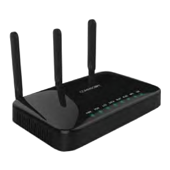
PO N solution Appearance Figure 1 Front view of C1004W Designed to be installed either wall mount or the desk placement. Physical dimension & weight 288.50(W) x 186.6(D) x 150.00(H) mm 820g Power adapter Input: 100 ~ 200VAC, 50 ~ 60 Hz... -
Page 7: Ports
PO N solution Ports Figure 2 Rear view of C1004W Table 1 Descriptions of the ports on the rear panel of the C1004W Port and Button Function Four Gigabit Ethernet ports Four 10/100/1000Base-TX ports used for service connection Updated system image is downloaded via this. -
Page 8: Leds
PO N solution LEDs Figure 3 Top view of C1004W Table 2 Descriptions of the LEDs on the front panel of the C1004W Silk Screen Name Status Indication Green On Power is fed. Power supply LED No power is fed. -
Page 9: Contents Of The Package
PO N solution Contents of the Package Power Adapter Transceiver module C1004W Installation Guide Quick Install Guide Ethernet Cable Star-shaped screws C1004W Installation Guide... -
Page 10: Installation
Connect the SC/APC connector on one end of a single-mode optical fiber into the optical terminal of the optical outlet (it could be a splitter or PIM card of an OLT) and the other end into the PON port of C1004W by pushing it until a click sound is heard. Step 4:... - Page 11 6-lobe star wrench (a special tool which is not enclosed). Step 6: Connect any LAN port of C1004W and a PC with an Ethernet cable which has RJ-45 plug head. Up to 4 PCs or its equivalent (e.g. IP phone) can be accommodated.
-
Page 12: Led Indicator
PO N solution LED Indicator The following steps can be referenced to see if the unit is in normal status when all the necessary connection for the unit is completed. Make sure that the POWER LED is ON. Make sure that the PON LED is ON in several seconds or minutes. -
Page 13: Web Gui Configuration Setting
VLAN assignment is presented later in this section. Web Login In order to configure C1004W via Web GUI page, connect your PC to any port of C1004W service ports with the enclosed RJ-45/UTP cable. After connecting PC on a LAN port, type http://192.168.1.1... -
Page 14: Vlan Assignment
PO N solution Note If it does not work, after pushing RESET button at the rear of system, then wait one or two minutes and try it again. VLAN assignment Go to the menu item in the left side of starting window. Select ‘Advance setup’... - Page 15 Click ‘Add’ button. Select an entry among ‘WAN Inteface used in the grouping’ menu. Move as many interfaces as wish from the right box to left. Then the moved interface will be assigned to the newly created VLAN Id. C1004W Installation Guide...
- Page 16 PO N solution In the example two physical interfaces of port 1 and port 2 are moved to ‘Group LAN Interface’. Check out to see if VLAN 100 is associated with port 1 and port 2 in the table shown below. (you may again select ‘Advance setup’...
-
Page 17: Device Info
PO N solution Device Info Device Info shows the basic information about ONU. The information to be able to search is as follows: WAN status and IP Information Statistics information about WAN / LAN / WLAN C1004W Installation Guide... - Page 18 PO N solution Route Information ARP Information DHCP Information assigned with LAN / WLAN...
-
Page 19: Advanced Setup / Wan Service
PO N solution Advanced Setup / WAN Service You can create the Interface for various WAN service based on the assigned WAN Physical Port. To create WAN Service Interface, click [Add] button on [WAN Service Setup Display]. C1004W Installation Guide... - Page 20 PO N solution If you click [Next] button, you can assign VLAN ID about 802.1Q and a priority about WAN service type and 802.1P. Note In case of assigning as Untagged Service from WAN Service Interface, you must set it as ‘-1’.
- Page 21 When the system uses the static IP address on WAN Service Interface, select [Use the following Static IP address]. Then set Static IP Address, Subnet Mask and Gateway IP Address. If you click [Next] button, you can enable NAT and Multicast function on the WAN service Interface. C1004W Installation Guide...
- Page 22 PO N solution If you click [Next] button, you can assign Default Gateway about WAN Service Interface. If you click [Next] button, you can set DNS Server about WAN Service Interface.
- Page 23 If you change 802.1P, 802.1Q on the created WAN Service Interface, you must register again after deleting WAN Service. Note In case that you assign 802.1Q VLAN-ID individually on the several WAN Service and do grouping LAN Interfaces, refer to Interface Grouping setting on Advanced Setup Section. C1004W Installation Guide...
-
Page 24: Advanced Setup / Interface Grouping
PO N solution Advanced Setup / Interface Grouping By creating several groups, you can manage several LAN Interfaces with Interface grouping provided from Advanced setup. By default, one default group includes all LAN Interfaces. To create Interface Group, click [Add] button on [Interface Group Display] Set Group Name with easy name to acknowledge. - Page 25 Group, one WAN interface per Group system is applied. Thus, to set like the following screen, you must add WAN interface before creating Group. Note To know the way of adding WAN Interface, refer to [Advanced Setup / WAN Service]. C1004W Installation Guide...
-
Page 26: Wireless / Basic
PO N solution Wireless / Basic You can set the basic Wireless configuration. It provides 4 Wireless interfaces and you can set each WLAN activation and Scanning activation from network list. It is possible to set SSID and a nation for wireless channel. -
Page 27: Wireless / Security
128Bit : 13 or 26 security key 802.1X Uses Radius Server / WEP key WPA2 Advanced WPA WPA2-PSK WPA / WAPI passphrase Key Mixed WPA2 /WPA Mixed WPA and WPA2 Mixed WPA2 / WPA- Mixed WPA-PSK and WPA2-PSK C1004W Installation Guide... - Page 28 PO N solution To apply “Shared” that is the most basic Network Authentication way, Select “Shared” on the Authentication Select Box. Note When you select each Network Authentication way, the screen shows the different setting options. Note You can select Current Network Key among 1~4. We recommend changing a new Network key value instead of default value.
-
Page 29: Wireless / Advanced
It is possible to set the advanced setting about Wireless LAN Interface. You can set the specific channel to want to run. You can set the transmission speed according to bandwidth and Beacon interval for AP. Note You can use 2.4GHZ Band in wl1, 5GHZ Band in wl0. C1004W Installation Guide... -
Page 30: Troubleshooting
Make sure that the ONU is turned on. Once you turn on the power, the POWER LED on the front panel of C1004W should be lit. If the POWER LED is not lit, please check if the power cable is connected to the power inlet of ONU properly. - Page 31 Step 3 If the diagnosis result of step 2 says that C1004W has got any fault at its uplink interface(i.e. Xenu), then reboot the uplink interface part of the unit. Use the CLI of ‘clear cable modem all reset’ to reboot the unit.
-
Page 32: Specification
PO N solution Specification Item Description Standard IEEE 802.1q Type Desktop System Architecture Size (mm) 288.50(W) x 186.60 (D) x 150.00(H) (incl. antenna) Weight 820g Input: 100 ~ 220VAC, 50~60Hz Power Output: 12VDC, 3A (The input terminal that a power adaptor is connected to) Consumption: Max 34W PON interface 10/10, 10/1, 2/1, 1/1 Gbps supported... - Page 33 OLT detects EPON Signal Strength to check the status of ONU signal Maintenance diagnostic received/transmitted based on Transmission distance: 10Km or 20Km(Optional) Optical characteristics Transmission quality: BER 10-10 or lower Physical Transmission level : -1~4dBm Characteristics Dielectric resistance 100Mohm or higher (based on DC 500V) C1004W Installation Guide...
- Page 34 PO N solution IEEE Std 802.3™-2002 Carrier sense multiple access with collision detection (CSMA/CD) access method and physical layer specifications IEEE Std 802.11n: Wireless Local Area Networks IEEE Std 802.1D, 1998 Edition Media Access Control (MAC) Bridges IEEE Std 802.1Q, 2003Edition Virtual Bridged Local Area Networks IEEE Std 802.1w-2001 Media Access Control (MAC) Bridges —...
- Page 35 5. Warning Please carefully select the installation position and make sure that the final output power does not exceed the limit set force in relevant rules. The violation of the rule could lead to serious federal penalty. C1004W Installation Guide...
Need help?
Do you have a question about the C1004W and is the answer not in the manual?
Questions and answers