Table of Contents
Advertisement
SERVICE MANUAL
AIR-CONDITIONER
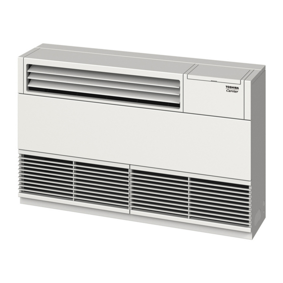
<Floor Console Exposed Type>
MML-AP0074H2UL
MML-AP0094H2UL
MML-AP0124H2UL
MML-AP0154H2UL
MML-AP0184H2UL
MML-AP0244H2UL
Revision 1 : Jun., 2016
Revision 2 : Jun., 2017
(MULTI TYPE)
<Floor Console Recessed Type>
MML-AP0074BH2UL
MML-AP0094BH2UL
MML-AP0124BH2UL
MML-AP0154BH2UL
MML-AP0184BH2UL
MML-AP0244BH2UL
PRINTED IN JAPAN, Mar., 2016, TOMO
FILE No. A10-1602
Advertisement
Table of Contents
Troubleshooting

Related Manuals for Toshiba MML-AP0124H2UL


Summary of Contents for Toshiba MML-AP0124H2UL
-
Page 1: Service Manual
Revision 1 : Jun., 2016 Revision 2 : Jun., 2017 SERVICE MANUAL AIR-CONDITIONER (MULTI TYPE) <Floor Console Exposed Type> <Floor Console Recessed Type> MML-AP0074H2UL MML-AP0074BH2UL MML-AP0094H2UL MML-AP0094BH2UL MML-AP0124H2UL MML-AP0124BH2UL MML-AP0154H2UL MML-AP0154BH2UL MML-AP0184H2UL MML-AP0184BH2UL MML-AP0244H2UL MML-AP0244BH2UL PRINTED IN JAPAN, Mar., 2016, TOMO... -
Page 2: Table Of Contents
CONTENTS SAFETY CAUTION ..............3 1. SPECIFICATIONS ..............8 2. CONSTRUCTION VIEWS (EXTERNAL VIEWS)....10 3. WIRING DIAGRAM ............16 4. PARTS RATING ..............18 5. REFRIGERATING CYCLE DIAGRAM ......19 6. CONTROL OUTLINE ............20 7. APPLIED CONTROL AND FUNCTION ......26 8. TROUBLESHOOTING ............47 9. DETACHMENTS ...............69 10. -
Page 3: Safety Caution
SAFETY CAUTION The important contents concerned to the safety are described on the product itself and on this Service Manual. Please read this Service Manual and understand the described items thoroughly in the following contents (Indications/Illustrated marks), and keep the manual for reference. The manufacturer shall not assume any liability for the damage caused by not observing the description of this manual. - Page 4 WARNING Before troubleshooting or repair work, check the ground wire is connected to the ground terminals of the main unit, otherwise an electric shock is caused when a leak occurs. If the ground wire is not correctly connected, contact an electrician for rework. Check ground wires.
- Page 5 WARNING After the work has finished, be sure to use an insulation tester set (500V Megger) to check the resistance is 2M or more between the charge section and the non-charge metal section (Ground position). If the resistance value is low, a disaster such as a leak or electric shock is caused at user’s Insulator check side.
- Page 6 • Refrigerant (R410A) This air conditioner adopts a HFC type refrigerant (R410A) which does not deplete the ozone layer. 1. Safety Caution Concerned to Refrigerant (R410A) The pressure of R410A is high 1.6 times of that of the previous refrigerant (R22). Accompanied with change of refrigerant, the refrigerating oil has been also changed.
- Page 7 4. Tools 1. Required Tools for R410A Mixing of different types of oil may cause a trouble such as generation of sludge, clogging of capillary, etc. Accordingly, the tools to be used are classified into the following three types. 1) Tools exclusive for R410A (Those which cannot be used for conventional refrigerant (R22)) 2) Tools exclusive for R410A, but can be also used for conventional refrigerant (R22) 3) Tools commonly used for R410A and for conventional refrigerant (R22) The table below shows the tools exclusive for R410A and their interchangeability.
-
Page 8: Specifications
1. SPECIFICATIONS 1-1. Floor console exposed Type Model name MML- AP0074H2UL AP0094H2UL AP0124H2UL AP0154H2UL Cooling capacity kBtu/h 12.0 15.4 Heating Capacity kBtu/h 10.5 13.5 17.0 Electrical Power supply 230V(208V/230V) 1phase 60Hz charastaristics Power consumption 208V 0.049 0.049 0.080 0.080 230V 0.058 0.058 0.093... - Page 9 1-2. Floor console recessed Type Model name MML- AP0074BH2UL AP0094BH2UL AP0124BH2UL AP0154BH2UL Cooling capacity kBtu/h 12.0 15.4 Heating Capacity kBtu/h 10.5 13.5 17.0 Electrical Power supply 230V(208V/230V) 1phase 60Hz charastaristics Power consumption 208V 0.047 0.047 0.047 0.095 230V 0.056 0.056 0.056 0.114 Appearance...
-
Page 10: Construction Views (External Views)
2. CONSTRUCTION VIEWS (EXTERNAL VIEWS) 2-1. Floor Console Exposed Type MML-AP0074H2UL, AP0094H2UL, AP0124H2UL Unit : in (mm) – 10 –... - Page 11 MML-AP0154H2UL, AP0184H2UL Unit : in (mm) – 11 –...
- Page 12 MML-AP0244H2UL Unit : in (mm) – 12 –...
- Page 13 2-2. Floor Console Recessed Type MML-AP0074BH2UL, AP0094BH2UL, AP0124BH2UL Unit : in (mm) – 13 –...
- Page 14 MML-AP0154BH2UL, AP0184BH2UL Unit : in (mm) – 14 –...
- Page 15 MML-AP0244BH2UL Unit : in (mm) – 15 –...
-
Page 16: Wiring Diagram
3. WIRING DIAGRAM 3-1. Floor Console Exposed Type MML-AP0074H2UL, AP0094H2UL, AP0124H2UL, AP0154H2UL, AP0184H2UL, AP0244H2UL – 16 –... - Page 17 3-2. Floor Console Recessed Type MML-AP0074BH2UL, AP0094BH2UL, AP0124BH2UL, AP0154BH2UL, AP0184BH2UL, AP0244BH2UL – 17 –...
-
Page 18: Parts Rating
4. PARTS RATING Floor Console Exposed Type Model MML-AP 0074H 0094H 0124H 0154H 0184H 0244H SWA-200U19A4A AF-200-45-4FU AF-200-70-4KU Running condenser for fan motor AC450 V, 1.5 μF AC450 V, 2 μF AC400 V, 2.5 μF TT12 EDM-MD12TF-3 EDM-B25YGTF EFM-40YGTF Lead wire length: 32" (818 mm) Vinyl tube 0.16"... -
Page 19: Refrigerating Cycle Diagram
5. REFRIGERATING CYCLE DIAGRAM Liquid side Gas side Strainer Capillary tube Air heat exchanger at indoor side Pulse Motor Valve (PMV) Strainer Sensor (TCJ) Sensor (TC2) Sensor (TC1) Sensor Fan motor (TA) Functional part name Functional outline Pulse Motor Valve (Connector CN082 (6P): Blue) 1) Controls super heat in cooling operation 2) Controls subcool in heating operation... -
Page 20: Control Outline
6. CONTROL OUTLINE Item Outline of specifications Remarks When power 1) Distinction of outdoor unit supply is reset When the power supply is reset, the outdoors are distinguished and the control is selected according to the distinguished result. 2) If resetting the power during a problem, the check code is cleared. - Page 21 Item Outline of specifications Remarks Automatic 1) Based on the difference between TA and TS, the capacity control operation capacity is determined by the outdoor unit. COOL HEAT ˚F (˚C) ˚F (˚C) +3.6 (+2) +1.8 (+1) +1.8 (+1) TS: Setup temp. TA: Room temp.
- Page 22 Item Outline of specifications Remarks Fan speed <HEAT> selection (Continued) TA ˚F (˚C) L <L> (– 0.9) – 1.8 [(– 0.5) – 1.0] L <H> (0) Tsh H <H> (+0.9) +1.8 [(+0.5) +1.0] <HH> (+1.8) +3.6 [(+1.0) +2.0] (+2.7) +5.4 [(+1.5) +3.0] <HH>...
- Page 23 Item Outline of specifications Remarks Freeze prevention 1. In all cooling operation, the air conditioner operates control as described below based upon temp.detected by (Low temp. release) TC1, TC2 and TCJ sensors. • When “J” zone is detected for 5 minutes, the thermostat is forced to turn off.
- Page 24 Item Outline of specifications Remarks Recovery control The indoor unit which is in STOP/Thermostat-OFF • The indoor unit which is for heating status or which operates in [FAN] mode performs the under thermostat-OFF refrigerant (Oil) following controls when it receives the heating (COOL) status or which refrigerant (Oil) recovery signal from the outdoor unit.
- Page 25 Item Outline of specifications Remarks Display of < READY> Displayed on the remote control • <READY > display [READY] 1) When the following check codes are indicated No display for wireless [HEAT READY] type remote control • Open phase of power supply wiring [P05] was detected. •...
-
Page 26: Applied Control And Function
7. APPLIED CONTROL AND FUNCTION 7-1. Indoor Control Block Diagram 7-1-1. When Main (Simple) Wired Remote Control Connected – 26 –... - Page 27 7-1-2. When Wireless Remote Controlr Kit Connected – 27 –...
- Page 28 7-1-3. When Both Wired (Simple) Remote Control and Wireless Remote Control Kit Connected – 28 –...
- Page 29 7-1-4. Indoor Printed Circuit Board MCC-1403 – 29 –...
- Page 30 P.C. Board Optional Switch/Connector Specifications Connector Function Specifications Remarks Start / stop input for HA (J01: In place / Removed = Start / stop input Pulse input (factory default) / Step input) 0 V (COM) Remote control disabling input Enables / disables start / stop control via remote control CN061 In-operation output ON during operation (HA answerback signal)
- Page 31 7-2. Functions at test run Cooling/Heating test run check The test run for cooling/heating can be performed from either indoor remote control or outdoor interface P.C. board. 1. Start/Finish operation of test run Test run from indoor remote control Wired remote control: Refer to the below item of “Test run” of the wired remote control. Wireless remote control: Refer to the next page item of “Test run”...
- Page 32 <In case of wireless remote control (TCB-AX32-UL)> 1. When TEMPORARY button is pushed for 10 seconds or more, Pi!” sound is heard and the operation changes to a forced cooling operation. After approx. 3 minutes, a cooling operation is forced to start. Check if cool air starts blowing.
- Page 33 7-3. Method to Set Indoor Unit Function DN Code (When performing this task, be sure to use a wired remote control) <Procedure> To be performed only when system at rest Push the buttons simultaneously and hold for at least 4 seconds. The unit No.
- Page 34 Function CODE No. (DN Code) Table (Includes All Functions Needed to Perform Applied Control on Site) Item Description At shipment Filter display delay timer 0000: None 0001: 150H According to type 0002: 2500H 0003: 5000H 0004: 10000H 02 Dirty state of filter 0000: Standard 0000: Standard 0001: High degree of dirt (Half of standard time)
- Page 35 7-4. Applied Control in Indoor Unit Remote location ON/OFF control box (TCB-IFCB-4UL) [Wiring and setup] • Use the exclusive connector for connection with the indoor control P.C. board. • In a group control, the system can operate when connecting with any indoor unit (Control P.C. board) in the group.
- Page 36 Ventilating fan control from remote control [Function] • The start/stop operation can be operated from the wired remote control when air to air heat exchanger or ventilating fan is installed in the system. • The fan can be operated even if the indoor unit is not operating. •...
- Page 37 Leaving-ON prevention control [Function] • This function controls the indoor units individually. It is connected with cable to the control P.C. board of the indoor unit. • In a group control, it is connected with cable to the indoor unit (Control P.C. board), and the CODE No. is set to the connected indoor unit.
- Page 38 Address setup (Manual setting from Wired remote control) In case that addresses of the indoor units will be determined prior to piping work after wiring work • Set an indoor unit per a remote control. • Turn on power supply. (Example of 2-lines cabling) (Real line: Wiring, Broken line: Refrigerant pipe) Push...
- Page 39 Confirmation of indoor unit No. position 1. To know the indoor unit addresses though position of the indoor unit is recognized • In case of individual operation (Wired remote control : indoor unit = 1 : 1) (Follow to the procedure during operation) <Procedure>...
- Page 40 How to check all the unit No. from an arbitrary wired remote control <Procedure> Carry out this procedure when the system is turned off. The indoor unit No. and the position in the identical refrigerant piping can be checked. An outdoor unit is selected, the identical refrigerant piping and the indoor unit No. are displayed one after the other, and then its fan is on.
- Page 41 How to change an indoor unit address by using a wired remote control Use this method to change the address of indoor units (one to one or group control) that have had the original address set automatically. This procedure must be done while the units are not operating. Simultaneously push and hold the “SET ”, “CL ”, and “TEST...
- Page 42 How to change all indoor addresses from an arbitrary wired remote control (It is possible when setting has finished by automatic addresses.) Contents: The indoor unit addresses in each identical refrigerant piping line can be changed from an arbitrary wired remote control. Enter in address check/change mode and then change the address.
- Page 43 Function to clear the check code 1. Clearing method from remote control How to clear the check code of outdoor unit The currently detected check code of the outdoor unit is cleared by using the service monitor function of the remote control. (Check code of the indoor unit is not cleared.) (Only the check code of the outdoor unit in one refrigerant line system is cleared.) <Method>...
- Page 44 Monitoring function of remote control switch When using the remote control (Model Name: RBC-AMT32UL), the following monitoring function can be utilized. Calling of display <Contents> The temperature of each sensor of the remote control, indoor unit and outdoor unit and the operating status can be checked by calling the service monitor mode from the remote control.
- Page 45 < Based on the SMMS-e > CODE No. Data name Display format Unit Remote control display example Room temperature (Use to control) ×1 °C [0027] = 27 °C Room temperature (Remote control) ×1 °C Indoor suction air temperature (TA) ×1 °F Indoor coil temperature (TCJ) ×1...
- Page 46 Changing of settings for Celsius display • Push ON / OFF button if the unit stops. Procedure 1 Push simultaneously buttons for 4 seconds or more. After a while, the display part flashes as shown right. Check the displayed CODE No. is [ •...
-
Page 47: Troubleshooting
8. TROUBLESHOOTING 8-1. Overview (1) Before engaging in troubleshooting (a) Applicable models All Super Module Multi (SMMS-i, SMMS-e) models. ∗ ∗∗∗ ∗∗∗ (Indoor units: MM , Outdoor units: MMY-MAP (b) Tools and measuring devices required • Screwdrivers (Philips, flat head), spanners, long-nose pliers, nipper, pin to push reset switch, etc. •... -
Page 48: Troubleshooting Method
8-2. Troubleshooting Method The remote controls (main remote control and central control remote control) and the interface P.C. board of an outdoor unit are provided with an LCD display (remote control) or a 7-segment display (outdoor interface P.C. board) to display operational status. Using this self-diagnosis feature, the problem may be identified in the event of a problem by following the method described below. - Page 49 (Trouble detected by main remote control) Check code Display of receiving unit Outdoor 7-segment display Indicator light block Typical fault site Description of trouble Main remote control Operation Timer Ready Sub-code Flash No master remote control, Signals cannot be received from indoor unit; –...
- Page 50 List of Check Codes (Outdoor Unit) (Check code detected by SMMS-e outdoor interface - typical examples) If “HELLO” is displayed on the oudoor 7-segment for 1 minute or more, turn off the power supply once and then turn on the power supply again after 30 seconds or more. When the same symptom appears, it is considered there is a IPDU: Intelligent Power Drive Unit (Inverter P.C.
- Page 51 Check code Display of receiving unit Outdoor 7-segment display TCC-LINK Indicator light block central control Typical problem site Description of problem or main remote Operation Timer Ready Sub-code Flash control display Outdoor heat exchanger Outdoor heat exchanger gas side temperature 01: TG1 gas side temperature sensors (TG1, TG2) have been open/...
- Page 52 Check code Display of receiving unit Outdoor 7-segment display TCC-LINK Indicator light block central control Typical problem site Description of problem or main remote Operation Timer Ready Sub-code control Flash display A3-IPDU Fan-IPDU A3-IPDU Fan-IPDU There are insufficient number of IPDUs (P.C. Trouble in number IPDUs boards) in inverter box.
- Page 53 (Check code detected by IPDU featuring in SMMS-e standard outdoor unit - typical examples) Check code Display of receiving unit Outdoor 7-segment display TCC-LINK Indicator light block Typical problem site Description of proplem central control or main remote Operation Timer Ready Sub-code control Flash...
- Page 54 8-3. Troubleshooting Based on Information Displayed on Remote Control Using main remote control (RBC-AMT32UL) (1) Checking and testing When a fault occurs to an air conditioner, a check code and indoor unit No. are displayed on the display window of the remote control. Check codes are only displayed while the air conditioner is in operation.
- Page 55 Using indoor unit indicators (receiving unit light block) (wireless type) To identify the check code, check the 7-segment display on the header unit. To check for check codes not displayed on the 7-segment display, consult the “List of Check Codes (Indoor Unit)” in “8-2. Troubleshooting Method”. : Goes off : Lighting : Blinking (0.5 seconds)
- Page 56 Heat exchanger temperature sensor (TCJ) trouble Operation Timer Ready Heat exchanger temperature sensor (TC2) trouble Indoor unit temperature sensor Heat exchanger temperature sensor (TC1) trouble troubles Ambient temperature sensor (TA/TSA) trouble Alternate blinking Discharge temperature sensor (TF) trouble Discharge temperature sensor (TD1) trouble Operation Timer Ready Discharge temperature sensor (TD2) trouble...
- Page 57 Light block Check code Cause of fault Operation Timer Ready Outdoor EEPROM trouble Synchronized blinking Other (indications not involving check code) Light block Check code Cause of fault Operation Timer Ready – Test run in progress Synchronized blinking Operation Timer Ready Setting incompatibility –...
- Page 58 8-4. Check Codes Displayed on Remote Control and SMMS-e Outdoor Unit (7-Segment Display on I/F Board) and Locations to Be Checked For other types of outdoor units, refer to their own service manuals. Check code Location Trouble detection Main Outdoor 7-segment display Description System status Check items (locations)
- Page 59 Check code Location Trouble detection Main Outdoor 7-segment display Description System status Check items (locations) condition(s) remote detection Check Sub-code control code Too many All stop • Combined capacity of indoor units • Check capacities of indoor units Overloading indoor units exceeds 135% of combined connected.
- Page 60 Check code Location Trouble detection Main Outdoor 7-segment display Description System status Check items (locations) condition(s) remote detection Check Sub-code control code IPDU All stop Communication is disrupted • Check wiring and connectors A3-IPDU Fan-IPDU communication between IPDUs (P.C. involved in communication trouble boards) in inverter box.
- Page 61 Check code Location Trouble detection Main Outdoor 7-segment display Description System status Check items (locations) condition(s) remote detection Check Sub-code control code 01: TS1 sersor trouble TS1/TS2 All stop Sensor resistance is infinity or zero • Check connection of TS1/TS3 03: TS2 sersor trouble sensor trouble (open/short circuit).
- Page 62 Check code Location Trouble detection Main Outdoor 7-segment display Description System status Check items (locations) condition(s) remote detection Check Sub-code control code Activation of All stop Low-pressure Ps sensor detects • Check service valves to confirm low-pressure operating pressure lower than full opening (both gas and liquid protection 0.02MPa.
- Page 63 Check code Location Trouble detection Main Outdoor 7-segment display Description System status Check items (locations) condition(s) remote detection Check Sub-code control code 01: TK1 oil circuit trouble Oil level All stop No temperature change is detected • Check for disconnection of TK1 02: TK2 oil circuit trouble detection by TK1 despite compressor 1...
- Page 64 Check code Location Trouble detection Main Outdoor 7-segment display Description System status Check items (locations) condition(s) remote detection Check Sub-code control code Indoor Indoor capacity Stop of Capacity setting has not been Set indoor capacity. (DN = 11) — — unit not set corresponding...
- Page 65 Check code Location Trouble detection Main Outdoor 7-segment display Description System status Check items (locations) condition(s) remote detection Check Sub-code control code 01: Compressor 1 side IPDU Activation of All stop High-pressure SW is activated. • Check connection of highpressure 02: Compressor 2 side high-pressure SW connector.
- Page 66 Check code Location Trouble detection Main Outdoor 7-segment display Description System status Check items (locations) condition(s) remote detection Check Sub-code control code 01: TS condition All stop Protective shutdown due to • Check for insufficiency in leakdetection sustained suction temperature at or refrigerant quantity.
- Page 67 Check code Location Trouble detection Main Outdoor 7-segment display Description System status Check items (locations) condition(s) remote detection Check Sub-code control code #0:Element short circuit IPDU Outdoor fan All stop (Sub code: #0) • Check fan motor. IPDU trouble Fan IPDU over current protection •...
-
Page 68: Sensor Characteristics
8-5. Sensor Characteristics Indoor Unit Temperature sensor characteristics Temperature Resistance [˚F (˚C)] [k ] Resistance 32 (0) 33.9 [k ] 41 (5) 26.1 50 (10) 20.3 59 (15) 15.9 68 (20) 12.6 77 (25) 10.0 86 (30) 95 (35) 104 (40) 113 (45) 122 (50) 131 (55) -
Page 69: Detachments
9. DETACHMENTS 9-1. Floor Console Exposed Type WARNING CAUTION Be sure to turn off the power supply and the breaker Be sure to put on the gloves at disassembling work; and then start a work. otherwise an injury will be caused by a part, etc. Spare parts Work procedure Remarks... - Page 70 Spare parts Work procedure Remarks Refrigerant 1. Detachment cycle (1) Recover the refrigerant gas. assembly (2) Take off the connecting pipe. (Liquid pipe and gas pipe) (3) Following to works 1 of , and (1) to (10), detach the parts. (4) Take off the reinforcement plate.
- Page 71 Spare parts Work procedure Remarks M4 screw Fan assembly 1. Detachment (1) Following step 1 of , (1) to (3), (6 )and (7), detach the parts. (2) Take off the nut which fixes the fan assembly. (M6 nut: 1 position) (3) Draw out the fan assembly toward you.
- Page 72 Spare parts Work procedure Remarks Capacitor 1. Detachment (1) Following step 1 of and (1) to (2), detach the parts. (2) Remove the capacitor. (M4 screw: 1 position) 2. Attachment Following step 1 of , and (1) to (3), attach the parts as original in the reverse procedure.
- Page 73 9-2. Floor Console Recessed Type WARNING CAUTION Be sure to turn off the power supply and the breaker Be sure to put on the gloves at disassembling work; and then start a work. otherwise an injury will be caused by a part etc. Spare parts Work procedure Remarks...
- Page 74 Spare parts Work procedure Remarks Refrigerating 1. Detachment cycle (1) Recover the refrigerating gas. assembly (2) Remove the connecting pipes. (Liquid pipe and gas pipe) (3) Following to works in 1 of and (1) to (7), detach the parts. (4) Remove the filter. (No screw fixing) (5) Remove the wire guard.
- Page 75 Spare parts Work procedure Remarks PMV motor 1. Detachment PMV motor (1) Following to the works in 1 of and (3) to (9), detach the parts. (2) Peel butyl rubber which is adhered to the PMV body, loosen the nut fixing the PMV motor with a double spanner, and then remove the PMV motor.
- Page 76 Spare parts Work procedure Remarks Fan motor [AP007 to 012] 1. Detachment (1) Following to works of 1 of and (1) to (3), detach the parts. (2) Cut off the fixing band which fixes the fan motor lead. (Two positions) (3) Cut off the fixing band fixes the lead cover and the fan motor lead, and then remove the lead cover Fixing...
- Page 77 Spare parts Work procedure Remarks Fan motor 2. Attachment (Continued) Following to works of 1 of and (1) to (5), attach the parts as original in the reverse procedure. * When attaching the fan motor, be sure that the fan motor does not hit the motor base reinforcement plate.
- Page 78 Spare parts Work procedure Remarks Fan motor [AP015 to 024] (Continued) 1. Detachment (1) Following to works of 1 of and (1) to (3), detach the parts. (2) Cut off the fixing band which fixes the fan motor lead. (Two positions) (3) Cut off the fixing band fixes the lead cover and the fan motor lead, and then remove the lead cover Fixing band...
- Page 79 Spare parts Work procedure Remarks Fan motor 2. Attachment (Continued) Following to works of 1 of and (1) to (8), attach the parts as original in the reverse procedure. * When attaching the fan motor reinforcement plate, be sure that the fan motor reinforcement plate is not caught in the motor band.
- Page 80 Spare parts Work procedure Remarks Capacitor [AP007 to 012] 1. Detachment (1) Following to ‚1 of , and (1) to (3), detach the parts. (2) Remove the capacitor cover and remove the Capacitor capacitor lead from the capacitor. cover (M4 screw: 2 pieces) (3) Remove the capacitor.
-
Page 81: Board Exchange Procedures
10. P.C. BOARD EXCHANGE PROCEDURES Indoor unit 10-1.Replacement of indoor P.C. boards Part code Model type P.C. board type 431-6V-586 MML-AP BH2UL MCC-1403 431-6V-587 MML-AP H2UL MCC-1403 Points to note when replacing indoor P.C. board assembly The electrically erasable programmable read-only memory (hereinafter EEPROM, IC10) mounted on an indoor P.C. - Page 82 Method 2 If it is not possible to turn on the indoor unit or read the setting data from the P.C. board to be replaced via a wired remote control or operate the remote control due to the failure of its power supply circuit - Replacing EEPROM (IC10) (For the location of this component and the method to replace it, see the “EEPROM location diagram”...
- Page 83 Procedure 1: reading setting data from EEPROM (Read the setting data from EEPROM, including both the factory settings and any modifications made to them on site.) Push the buttons simultaneously and hold for at least 4 seconds. (This number corresponds to the same number shown on the Remote Control Operation Diagram.) * In the case of group control, the unit No.
- Page 84 Procedure 2: replacing P.C. board Replace the faulty P.C. board with a service P.C. board. Be sure to replicate the old jumper setting (removal), and connector short-circuit setting (e.g. CN030) on the service P.C. board. (See the diagram at below.) (MCC-1403) CN041 CN030...
- Page 85 Procedure 3: writing setting data in EEPROM (The EEPROM of the service P.C. board has been set to the factory default values.) Push the buttons simultaneously and <Fig. 1 RBC-AMT32UL> hold for at least 4 seconds. (This number corresponds to the same number shown on the Remote Control Operation Diagram.) (Under UNIT No., ALL is displayed.) At the same time, the CODE No.
- Page 86 EEPROM location diagram The EEPROM (IC10) is mounted on an IC socket. Use a pair of tweezers, etc. to remove it. When installing it, adjust its orientation as shown in the diagram below. During EEPROM removal / installation, take care not to bend IC leads. P.C.
-
Page 87: Exploded Views And Parts List
11. EXPLODED VIEWS AND PARTS LIST 11-1. Floor Console Exposed Type MML- AP0074H2UL, AP0094H2UL, AP0124H2UL, AP0154H2UL, AP0184H2UL, AP0244H2UL – 87 –... - Page 88 Q'ty/Set MML-AP Location Part No. Description 0244 0074 0094 0124 0154 0184 H2UL H2UL H2UL H2UL H2UL H2UL 43723020 CASE, FAN, LEFT 43723019 CASE, FAN, RIGHT 43126119 CASE, FAN, RIGHT 43109394 GRILL,INLET,WHITE 43166026 REMOTE CONTROLLER, SIMPLE, SX-U01EQ 43166013 REMOTE CONTROLLER, SX-TA01UE 43166014 REMOTE CONTROLLER, SX-TB01UE 43166029...
- Page 89 Electrical parts Q'ty/Set MML-AP Location Part No. Description 0074 0094 0124 0154 0184 0244 H2UL H2UL H2UL H2UL H2UL H2UL 43050425 SENSOR ASSY, SERVICE, TC (F6) : TC2, TCJ 43F50426 SENSOR, SERVICE, TA 43150320 SENSOR ASSY, SERVICE, TG (F4) : TC1 43158182 TRANSFORMER, TT-12 43160575...
- Page 90 11-2. Floor Console Recessed Type MML-AP0074BH2UL, AP0094BH2UL, AP0124BH2UL – 90 –...
- Page 91 Q'ty/Set MML-AP Location Part No. Description AP0074 AP0094 AP0124 BH2UL BH2UL BH2UL 43723020 CASE, FAN, LEFT 43126119 CASE, FAN, RIGHT 43166026 REMOTE CONTROLLER, SIMPLE, SX-U01EQ 43166013 REMOTE CONTROLLER, SX-TA01UE 43166014 REMOTE CONTROLLER, SX-TB01UE 43166029 REMOTE CONTROLLER 4314J543 REFRIGERATION CYCLE ASSY 43155179 CAPACITOR, 1.5MFD,450V 4312C153...
- Page 92 Electrical parts Q'ty/Set MML-AP Location Part No. Description AP0074 AP0094 AP0124 BH2UL BH2UL BH2UL 43050425 SENSOR ASSY, SERVICE ,TC (F6) : TC2, TCJ 43F50426 SENS0R, SERVICE, TA 43150320 SENSOR ASSY, SERVICE, TG (F4) : TC1 43158182 TRANSFORMER, TT-12 43160626 TERMINAL BLOCK, 2P, 20A 43160582 TERMINAL, 4P 4316V586...
- Page 93 MML-AP0154BH2UL, AP0184BH2UL, AP0244BH2UL – 93 –...
- Page 94 Q'ty/Set MML-AP Location Part No. Description AP0154 AP0184 AP0244 BH2UL BH2UL BH2UL 43723020 CASE, FAN, LEFT 43126119 CASE, FAN, RIGHT 43166026 REMOTE CONTROLLER, SIMPLE, SX-U01EQ 43166013 REMOTE CONTROLLER, SX-TA01UE 43166014 REMOTE CONTROLLER, SX-TB01UE 43166029 REMOTE CONTROLLER 4314J541 REFRIGERATION CYCLE ASSY 4314J542 REFRIGERATION CYCLE ASSY 43155175...
- Page 95 Electrical parts Q'ty/Set MML-AP Location Part No. Description AP0154 AP0184 AP0244 BH2UL BH2UL BH2UL 43050425 SENSOR ASSY, SERVICE ,TC (F6) : TC2, TCJ 43F50426 SENS0R, SERVICE, TA 43150320 SENSOR ASSY, SERVICE, TG (F4) : TC1 43158182 TRANSFORMER, TT-12 43160626 TERMINAL BLOCK, 2P, 20A 43160582 TERMINAL, 4P 4316V586...
- Page 96 WARNINGS ON REFRIGERANT LEAKAGE Important Check of Concentration Limit The room in which the air conditioner is to be installed requires a design that in the event of NOTE 2 : refrigerant gas leaking out, its concentration will The standards for minimum room volume are as follows. not exceed a set limit.
- Page 97 TOSHIBA CARRIER CORPORATION 72-34 Horikawa-cho, Saiwai-ku, Kawasaki-shi, Kanagawa 212-8585, JAPAN Copyright © 2017 TOSHIBA CARRIER CORPORATION, ALL Rights Reserved. Revision record First issue — — Mar., 2016 English was corrected. Page 3, 4, 5, 6, 10, 11, 12, 13, 14, 15, 19, 20, 21, 22,...