Mitsubishi Electric FR-E700 Instruction Manual
Hide thumbs
Also See for FR-E700:
- Instruction manual (608 pages) ,
- Basic instruction manual (149 pages) ,
- Installation manuallines (38 pages)
Table of Contents
Advertisement
INVERTER
FR-E700
FR-E720-0.1K to 15K
FR-E740-0.4K to 15K
FR-E720S-0.1K to 2.2K
FR-E710W-0.1K to 0.75K
Thank you for choosing this Mitsubishi Electric Inverter.
This Instruction Manual (Basic) provides handling information and precautions for use of the equipment.
Please forward this Instruction Manual (Basic) to the end user.
Outline ...................................................................................1
1
Installation And Wiring ...................................................6
2
Precautions For Use Of The Inverter.........................18
3
4
Driving The Motor.............................................................21
5
Energy Saving Operation For Fans And Pumps ........31
6
Parameters .........................................................................32
7
Troubleshooting ..............................................................37
8
Precautions For Maintenance And Inspection ........42
9
Specifications ....................................................................44
10
To obtain the Instruction Manual (Applied)
Contact where you purchased the inverter, your Mitsubishi Electric sales
representative, or the nearest Mitsubishi Electric FA Center for the
following manual:
Instruction Manual (Applied) [IB(NA)-0600277ENG]
This manual is required if you are going to utilize functions and
performance.
The PDF version of this manual is also available for download at
"MELFANS Web," the Mitsubishi Electric FA network service on the
world wide web (URL: http://www.MitsubishiElectric.co.jp/melfansweb).
CONTENTS
700
1
2
3
4
5
6
7
8
9
10
Advertisement
Table of Contents

Related Manuals for Mitsubishi Electric FR-E700


Summary of Contents for Mitsubishi Electric FR-E700
- Page 1 PRECAUTIONS FOR MAINTENANCE AND INSPECTION ..42 SPECIFICATIONS ..............44 To obtain the Instruction Manual (Applied) Contact where you purchased the inverter, your Mitsubishi Electric sales representative, or the nearest Mitsubishi Electric FA Center for the following manual: Instruction Manual (Applied) [IB(NA)-0600277ENG] This manual is required if you are going to utilize functions and performance.
-
Page 2: Instruction Manual (Basic)
This Instruction Manual (Basic) provides handling information and precautions for use of the equipment. Please forward this Instruction Manual (Basic) to the end user. 2. Fire Prevention This section is specifically about safety matters CAUTION Do not attempt to install, operate, maintain or inspect the Inverter must be installed on a nonflammable wall without inverter until you have read through the Instruction Manual holes (so that nobody touches the inverter heatsink on the... - Page 3 (2) Wiring (5) Emergency stop CAUTION CAUTION Do not install a power factor correction capacitor or surge A safety backup such as an emergency brake must be suppressor/capacitor type filter on the inverter output provided to prevent hazardous condition to the machine side.
- Page 4 <Abbreviation> PU: Operation panel and parameter unit (FR-PU04, FR-PU07) Inverter: Mitsubishi inverter FR-E700 series FR-E700: Mitsubishi inverter FR-E700 series Pr.: Parameter number (Number assigned to function) PU operation: Operation using the PU (operation panel/FR-PU04/FR-PU07) External operation: Operation using the control circuit signals...
-
Page 5: Outline
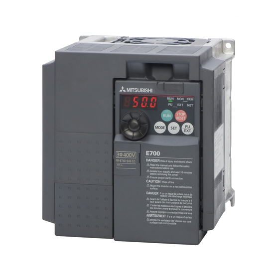
Product checking and parts identification 1 OUTLINE Product checking and parts identification Unpack the inverter and check the capacity plate on the front cover and the rating plate on the inverter side face to ensure that the product agrees with your order and the inverter is intact. Inverter model FR - E740... - Page 6 Operation panel Operation panel 1.2.1 Names and functions of the operation panel The operation panel cannot be removed from the inverter. Operating status indicator Operation mode indicator Lit or flicker during inverter operation. ∗ PU: Lit to indicate PU operation mode. EXT: Lit to indicate External operation mode.
- Page 7 Operation panel 1.2.2 Basic operation (factory setting) Operation mode switchover At power-ON (External operation mode) PU Jog operation mode (Example) PU operation mode Value change and frequency flicker. (output frequency monitor) Frequency setting has been written and completed!! STOP Output current monitor Output voltage monitor Display the Parameter setting mode...
-
Page 8: Changing The Parameter Setting Value
Operation panel 1.2.3 Changing the parameter setting value Changing Change the Pr. 1 Maximum frequency setting. example Operation Display Screen at power-ON The monitor display appears. PU indicator is lit. Press to choose the PU operation mode. PRM indicator is lit. Press to choose the parameter setting mode. - Page 9 Operation panel 1.2.4 Parameter clear/all parameter clear POINT Set "1" in Pr.CL Parameter clear, ALLC all parameter clear to initialize all parameters. (Parameters are not cleared when "1" is set in Pr. 77 Parameter write selection.) Refer to the extended parameter list of the Instruction Manual (Applied) for parameters cleared with this operation.
-
Page 10: Installation And Wiring
Always install a thermal relay when using a brake resistor whose capacity is 11K or higher. (Refer to page 17) EMC filter (ferrite core) * Inverter (FR-E700) (FR-BSF01, FR-BLF) EMC filter (ferrite core) R/L1 S/L2 T/L3 Install an EMC filter (ferrite core) - Page 11 Peripheral devices Peripheral devices Check the inverter model of the inverter you purchased. Appropriate peripheral devices must be selected according to the capacity. Refer to the following list and prepare appropriate peripheral devices. Moulded Case Circuit Breaker Magnetic Contactor (MC) (MCCB) ∗1 Motor...
- Page 12 Installation of the inverter and instructions Installation of the inverter and instructions (1) Installation of the inverter Enclosure surface mounting Remove the front cover and wiring cover to fix the inverter to the surface. (Remove the covers in the directions of the arrows.) FR-E720-0.1K to 0.75K FR-E720-1.5K to 3.7K FR-E720-5.5K to 15K...
-
Page 13: Terminal Connection Diagram
Wiring Wiring 2.3.1 Terminal connection diagram 1. DC reactor (FR-HEL) Sink logic When connecting a DC reactor, remove the Main circuit terminal jumper across P1 and P/+. *6 Terminal P1 is not available for single- Control circuit terminal Not available for single-phase 100V power phase 100V power input model. -
Page 14: Terminal Specifications
Wiring 2.3.2 Terminal specifications Terminal Type Terminal Name Description Symbol Connect to the commercial power supply. Keep these terminals open when using the high R/L1, S/L2, AC power input power factor converter (FR-HC) or power regeneration common converter (FR-CV). T/L3 * ∗... - Page 15 Wiring Terminal Type Terminal Name Description Symbol 1 changeover contact output indicates that the inverter fault occurs. Relay output A, B, C Fault: discontinuity across B-C (continuity across A-C), Normal: continuity across B-C (fault output) (discontinuity across A-C) Contact capacity 230VAC 0.3A (power factor = 0.4) 30VDC 0.3A Switched Low when the inverter output frequency is equal to or Permissible load 24VDC Inverter running...
- Page 16 Wiring FR-E720-11K, 15K FR-E740-11K, 15K P/+ PR R/L1 S/L2 T/L3 R/L1 S/L2 T/L3 Jumper Jumper Power supply Motor Power supply Motor Single-phase 200V class FR-E720S-0.1K to 0.4K FR-E720S-0.75K to 2.2K Jumper N/- P/+ Jumper R/L1 S/L2 R/L1 S/L2 Motor Power supply Power supply Motor Single-phase 100V class...
- Page 17 Wiring Cable size and other specifications of the main circuit terminals and the earthing terminal Select the recommended cable size to ensure that a voltage drop will be 2% at maximum. If the wiring distance is long between the inverter and motor, a main circuit cable voltage drop will cause the motor torque to decrease especially at the output of a low frequency.
- Page 18 Wiring The line voltage drop can be calculated by the following formula: 3 × wire resistance[mΩ/m] × wiring distance[m] × current[A] Line voltage drop [V]= 1000 Use a larger diameter cable when the wiring distance is long or when it is desired to decrease the voltage drop (torque reduction) in the low speed range.
-
Page 19: Wiring Of Control Circuit
Wiring 2.3.4 Wiring of control circuit Terminal layout Terminal screw size M3: (Terminal A, B, C) M2: (Other than the above) 4 RUN FU SE STF STR Wiring method 1) Strip off the sheath of the wire of the control circuit to wire. Strip off the sheath about the length below. - Page 20 Wiring (1) Control circuit common terminals (SD, 5, SE) Terminals SD, SE and 5 are common terminals for I/O signals. (All common terminals are isolated from each other.) Do not earth them. Avoid connecting the terminals SD and 5 and the terminals SE and 5. Terminal SD is a common terminal for the contact input terminals (STF, STR, RH, RM, RL, MRS, RES) and frequency output signal (FM).
- Page 21 Connection of a dedicated external brake resistor (MRS type, MYS type, FR-ABR) Connection of a dedicated external brake resistor (MRS type, MYS type, FR-ABR) Install a dedicated brake resistor (MRS type, MYS type, FR-ABR) outside when the motor driven by the inverter is made to run by the load, quick deceleration is required, etc.
-
Page 22: Precautions For Use Of The Inverter
PRECAUTIONS FOR USE OF THE INVERTER 3 PRECAUTIONS FOR USE OF THE INVERTER The FR-E700 series is a highly reliable product, but incorrect peripheral circuit making or operation/handling method may shorten the product life or damage the product. Before starting operation, always recheck the following points. - Page 23 PRECAUTIONS FOR USE OF THE INVERTER (11) Across terminals P/+ and PR, connect only an external regenerative brake discharging resistor. Do not connect a mechanical brake. The brake resistor can not be connected to the 0.1K(SC) or 0.2K(SC). Leave terminals P/+ and PR open. Also, never short between these terminals.
- Page 24 FAILSAFE OF THE SYSTEM WHICH USES THE INVERTER 4 FAILSAFE OF THE SYSTEM WHICH USES THE INVERTER When a fault occurs, the inverter trips to output a fault signal. However, a fault output signal may not be output at an inverter fault occurrence when the detection circuit or output circuit fails, etc.
-
Page 25: Driving The Motor
Start/stop from the operation panel (PU operation) 5 DRIVING THE MOTOR The inverter needs frequency command and start command. Frequency command Frequency command (set frequency) determines the rotation speed of the motor. Turning ON the start command starts the motor to rotate. Frequency Inverter output REMARKS... - Page 26 Start/stop from the operation panel (PU operation) 5.1.2 Setting the frequency by switches (three-speed setting) (Pr. 4 to Pr. 6) POINT Use the operation panel ( to give a start command. Switch ON the RH, RM, or RL signal to give a frequency command. Set "4"...
- Page 27 Start/stop from the operation panel (PU operation) 5.1.3 Setting the frequency by analog input (voltage input) POINT Use the operation panel ( to give a start command. Use the (frequency setting) potentiometer to give a frequency command. Set "4" (External/PU combined operation mode 2) in Pr. 79 Operation mode selection. [Connection diagram] Inverter (The inverter supplies 5V power to the...
- Page 28 Start and stop using terminals (External operation) Start and stop using terminals (External operation) POINT From where is the frequency command given? Operation at the frequency set in the frequency setting mode of the operation panel refer to 5.2.1 (Refer to page 24) Give a frequency command by switch (multi-speed setting) refer to 5.2.2 (Refer to page 25) Perform frequency setting by a voltage input signal...
- Page 29 Start and stop using terminals (External operation) 5.2.2 Setting the frequency by switches (three-speed setting) (Pr. 4 to Pr. 6) POINT Switch ON the STF (STR) signal to give a start command. Switch ON the RH, RM, or RL signal to give a frequency command. [Connection diagram] Inverter Speed 1...
- Page 30 Start and stop using terminals (External operation) 5.2.3 Setting the frequency by analog input (voltage input) POINT Switch ON the STF(STR) signal to give a start command. Use the potentiometer (frequency setting potentiometer) to give a frequency command. [Connection diagram] Inverter (The inverter supplies 5V power to the frequency setting potentiometer.
-
Page 31: Parameters
Start and stop using terminals (External operation) 5.2.4 Operating at 60Hz or higher using the external potentiometer < How to change the maximum frequency> Changing When you want to use 0 to 5VDC input frequency setting potentiometer to change the frequency at 5V from 60Hz (initial value) example to 70Hz, make adjustment to output "70Hz"... - Page 32 Acquiring large starting torque and low speed torque (Advanced magnetic flux vector control, General-purpose magnetic flux vector control) (Pr. 71, Pr. 80, Pr. 81, Pr. 800) Acquiring large starting torque and low speed torque (Advanced magnetic flux vector control, General-purpose magnetic flux vector control) (Pr.
-
Page 33: Test Run
Acquiring large starting torque and low speed torque (Advanced magnetic flux vector control, General-purpose magnetic flux vector control) (Pr. 71, Pr. 80, Pr. 81, Pr. 800) 5.3.1 Selection method of Advanced magnetic flux vector control Perform secure wiring. (Refer to page 9) Set the motor. - Page 34 Acquiring large starting torque and low speed torque (Advanced magnetic flux vector control, General-purpose magnetic flux vector control) (Pr. 71, Pr. 80, Pr. 81, Pr. 800) 5.3.2 Selection method of General-purpose magnetic flux vector control Perform secure wiring. (Refer to page 9) Set the motor.(Pr.
- Page 35 ENERGY SAVING OPERATION FOR FANS AND PUMPS 6 ENERGY SAVING OPERATION FOR FANS AND PUMPS Set the following functions to perform energy saving operation for fans and pumps. Load pattern selection (Pr. 14) Select the optimum output characteristic (V/F characteristic) that is suitable for the Pr.
- Page 36 Simple mode parameters 7 PARAMETERS Simple variable-speed operation can be performed with the inverter in the initial settings. Set the required parameters according to the load and operating conditions. Use the operation panel to set or change a parameter. (Refer to Chapter 4 of the Instruction Manual (Applied) for the detailed description of parameters.
- Page 37 Parameter list Parameter list REMARKS indicates simple mode parameters. (initially set to extended mode) The parameters surrounded by a black border in the table allow its setting to be changed during operation even if "0" (initial value) is set in Pr. 77 Parameter write selection. Setting Initial Setting...
- Page 38 Parameter list Setting Initial Setting Initial Parameter Name Parameter Name Range Value Range Value Retry waiting time 0.1 to 360s Terminal 4 frequency setting 0 to 400Hz 60Hz gain frequency Retry count display erase PID control automatic 0 to 400Hz, Special regenerative brake 9999 0 to 30%...
- Page 39 Parameter list Setting Initial Setting Initial Parameter Name Parameter Name Range Value Range Value RL terminal function selection 0 to 100s, Stop selection 1000 to 1100s, 9999 0 to 5, 7, 8, RM terminal function selection 8888, 9999 10, 12, RH terminal function selection 14 to 16, 18, Output phase loss protection...
- Page 40 Parameter list Setting Initial Setting Initial Parameter Name Parameter Name Range Value Range Value Stop mode selection at Frequency setting voltage bias 0, 1, 2, 3 communication error frequency (built-in 0 to 400Hz (922) ∗6∗7 potentiometer) Maintenance timer 0 (1 to 9998) Frequency setting voltage bias Maintenance timer alarm 0 to 9998,...
-
Page 41: Troubleshooting
Reset method of protective function 8 TROUBLESHOOTING When a fault occurs in the inverter, the inverter trips and the PU display automatically changes to one of the following fault or alarm indications. If the fault does not correspond to any of the following faults or if you have any other problem, please contact your sales representative. - Page 42 List of fault displays List of fault displays When a fault occurs in the inverter, the inverter trips and the PU display automatically changes to one of the following fault or alarm indications. The error message shows an operational error. The inverter output is not shut off. Warnings are messages given before faults occur.
- Page 43 List of fault displays Function Name Description Corrective action Display Set the acceleration time longer. (Shorten the downward acceleration time in vertical lift application.) If "E.OC1" always appears at start, disconnect the motor once and restart the inverter. If "E.OC1" still appears, the inverter may be faulty.
- Page 44 List of fault displays Function Name Description Corrective action Display The output frequency has dropped to 1Hz as a Reduce the load. (Check the Pr. 22 Stall prevention operation level Stall prevention stop result of deceleration due to the excess motor load. setting.) A fault has occurred in the brake circuit, such as a Brake transistor alarm...
- Page 45 Check first when you have a trouble Check first when you have a trouble Description Countermeasure Check start and frequency command sources and enter a start command (STF, etc.) and a Motor does not start. frequency command. Motor or machine is making abnormal Take EMC measures if a steady operation cannot be performed due to EMI.
-
Page 46: Precautions For Maintenance And Inspection
Inspection items 9 PRECAUTIONS FOR MAINTENANCE AND INSPECTION The inverter is a static unit mainly consisting of semiconductor devices. Daily inspection must be performed to prevent any fault from occurring due to the adverse effects of the operating environment, such as temperature, humidity, dust, dirt and vibration, changes in the parts with time, service life, and other factors. - Page 47 Replacement of parts Replacement of parts The inverter consists of many electronic parts such as semiconductor devices. The following parts may deteriorate with age because of their structures or physical characteristics, leading to reduced performance or fault of the inverter. For preventive maintenance, the parts must be replaced periodically. Use the life check function as a guidance of parts replacement.
-
Page 48: Specifications
Rating 10 SPECIFICATIONS 10.1 Rating Three-phase 200V power supply Model FR-E720- K 0.75 Applicable motor capacity (kW) ∗1 0.75 Rated capacity (kVA) ∗2 13.1 18.7 23.9 17.5 Rated current (A) ∗7 (0.8) (1.4) (2.5) (4.1) (10) (16.5) (23) (31) (44) (57) Overload current rating ∗3... - Page 49 Although the FR-E700 series has the built-in inrush current limit circuit, select the DC power supply considering the inrush current at powering ON as the inrush current four times of the rated inverter flows at powering ON.
- Page 50 Outline dimension drawings 10.3 Outline dimension drawings When used with the plug-in option * When the FR-A7NC E kit is mounted, a terminal block protrudes making the depth approx. 2mm greater. (Unit:mm) • Three-phase 200V class Inverter Type FR-E720-0.1K 80.5 95.6 FR-E720-0.2K FR-E720-0.4K...
- Page 51 CE marking. The authorized representative in the EU The authorized representative in the EU is shown below. Name: Mitsubishi Electric Europe B.V. Address: Gothaer Strasse 8, 40880 Ratingen, Germany Note We declare that this inverter, when equipped with the dedicated EMC filter, conforms with the EMC Directive in industrial environments and affix the CE marking on the inverter.
- Page 52 (2) Low Voltage Directive We have self-confirmed our inverters as products compliant to the Low Voltage Directive (Conforming standard EN 61800- 5-1) and affix the CE marking on the inverters. Outline of instructions ∗ Do not use an earth leakage circuit breaker as an electric shock protector without connecting the equipment to the earth. Connect the equipment to the earth securely.
- Page 53 ∗Select a UL and cUL certified fuse with Class T fuse equivalent cut-off speed or faster with the appropriate rating for branch circuit protection, or a UL489 molded case circuit breaker (MCCB) in accordance with the table below. FR-E720- 0.75 Rated fuse voltage(V) 240V or more Without power factor...
-
Page 54: Appendix 2 Instructions For Ul And Cul
Appendix 2 Instructions for UL and cUL (Standard to comply with: UL 508C, CSA C22.2 No. 14) 1. General Precaution The bus capacitor discharge time is 10 minutes. Before starting wiring or inspection, switch power off, wait for more than 10 minutes, and check for residual voltage between terminal P/+ and N/- with a meter etc., to avoid a hazard of electrical shock. - Page 55 MEMO...
- Page 56 MEMO...
- Page 57 REVISIONS *The manual number is given on the bottom left of the back cover. Print Date Revision Manual Number Dec. 2010 IB(NA)-0600441ENG-A First edition For Maximum Safety • Mitsubishi inverters are not designed or manufactured to be used in equipment or systems in situations that can affect or endanger human life.
-
Page 58: Motor Overload Protection
Additional notes for Instructions for UL and cUL Motor overload protection When using the electronic thermal relay function as motor overload protection, set the rated motor current in Pr.9 Electronic thermal O/L relay CAUTION Motor over temperature sensing is not provided by the drive. General precaution CAUTION - Risk of Electric Shock - The bus capacitor discharge time is 10 minutes. - Page 59 FR-E700 Series Instruction Manual Supplement For the FR-E700 series manufactured in December 2014 or later, the following specifications are added. Check the serial number printed on the rating plate of the inverter. Voltage reduction selection during stall prevention operation (Pr.154)
- Page 60 Operation FR-PU04 panel E.OV2 Stedy Spd OV FR-PU07 indication Name Regenerative overvoltage trip during constant speed If regenerative energy causes the inverter's internal main circuit DC voltage to reach or exceed the specified value, the protective circuit is activated to stop Description the inverter output.
- Page 61 SERIAL number check Check the serial number printed on the rating plate of the inverter. Refer to the inverter manual for the location of the rating plate. Rating plate example Symbol Year Month Control number SERIAL (Serial No.) The SERIAL consists of one symbol, two characters indicating production year and month, and six characters indicating control number.
- Page 62 MEMO BCN-C22005-679...
- Page 63 Year, and the Month is indicated by 1 to 9, X (October), Y (November), or Z (December). •Authorized sales representative (importer) in the CU area The authorized sales representative (importer) in the CU area is shown below. Name: Mitsubishi Electric (Russia) LLC Address: 52, bld 1 Kosmodamianskaya Nab 115054, Moscow, Russia Phone: +7 (495) 721-2070...
- Page 64 電器電子製品有害物質使用制限について 中華人民共和国の『電器電子製品有害物質使用制限管理弁法』に基づき、 「電器電子製 品有害物質使用制限の標識」の内容を以下に記載いたします。 Restricted Use of Hazardous Substances in Electronic and Electrical Products The mark of restricted use of hazardous substances in electronic and electrical products is applied to the product as follows based on the “Management Methods for the Restriction of the Use of Hazardous Substances in Electrical and Electronic Products”...
-
Page 65: Instructions For Ul And Cul
カナダ国内に設置する場合は分岐回路の保護はCanadian Electrical Code および現地の規格に 従って実施してください。 インバータが装備している短絡保護は、分岐回路を保護するものではありません。 また、分岐回路保護用のクラスT、クラスJ、クラスCCタイプのヒューズ以上の遮断速度を持つ適 切な定格のUL、cUL認定ヒューズ、もしくはUL489配線用遮断器(MCCB)を選定し、使用して ください。 FR-E700 Series Instruction Manual Supplement Instructions for UL and cUL have been revised. Instructions for UL and cUL (Standard to comply with: UL 508C, CSA C22.2 No. 14) Installation The below types of inverter have been approved as products for use in enclosure and approval tests were conducted under the following conditions. - Page 66 Model Manufacturer Rated Voltage, Vac MMP-T32 Mitsubishi Electric Corp. 480Y/277 Suitable for Use in a Circuit Capable of Delivering Not More Than 50 or 25 kA rms Symmetrical Amperes, 480Y/277 Volts Maximum when protected by the Type E Combination motor Controllers indicated in the above table.
- Page 67 Korean FA Center India FA Center MITSUBISHI ELECTRIC AUTOMATION KOREA CO., LTD. B1F,2F, 1480-6, Gayang-Dong, Gangseo-Gu, Seoul, 157-200, Mitsubishi Electric Asia Pvt. Ltd. Gurgaon Branch Korea 2nd Floor, DLF Building No.9B, DLF Cyber City Phase TEL. +82-2-3660-9607 FAX. +82-2-3664-0475 Gurgaon 122002, Haryana, India TEL.
- Page 68 HEAD OFFICE: TOKYO BUILDING 2-7-3, MARUNOUCHI, CHIYODA-KU, TOKYO 100-8310, JAPAN FR-E700 MODEL INSTRUCTION MANUAL (BASIC) MODEL 1A2-P25 CODE IB(NA)-0600441ENG-A(1012)MEE Printed in Japan Specifications subject to change without notice.