Table of Contents

Related Manuals for EST APC-TF Series

Summary of Contents for EST APC-TF Series
- Page 1 ACTIVE POWER CONTROLLER USER MANUAL MODEL APC-TF Series VER_2013.12 1125-2 Sankyok-dong, Puk-ku, Taegu, KOREA TEL : +82-53-355-3621 A/S : +82-10-3749-9074 FAX : +82-53-957-3622 mail : est-korea@hanmail.net http://cafe.daum.net/EST-KOREA...
-
Page 2: Active Power Controller Precautions
ACTIVE POWER CONTROLLER PRECAUTIONS The installation, configuration, commissioning and maintenance of the power unit should only be carried out by personnel qualified and trained to work with low voltage electrical equipment in an industrial environment. Safety symbols Item Precautions and description This symbol is marking contents about danger (electric shock, electrical impact etc..) that can happen by electric problem. - Page 3 GENERAL INTRODUCTION TO THE APC-TF SERIES Warranty of quality and A/S regulation of product Confirm ordering product specification and whether agree. Confirm whether it is no defect to damage or product while transport. Quality term of guarantee of this product is during 1 year when use normally.
-
Page 4: Understanding Scr Power Controls
Understanding SCR Power Controls When selecting SCR Power Controls, it is important to have a basic understanding of how SCRs work. This will help you select the right SCR for your application. • How SCR Power Controls Work A silicon controlled rectifier (SCR) is a solid state switching device which can provide fast, infinitely variable proportional control of electric power. -
Page 5: Power Control Selection Guide
POWER CONTROL SELECTION GUIDE The SCR power control can deliver electrical power to heaters in several ways: phase angle fired, zero voltage switched and on/off control. Phase angle fired controls proportionally turn on a percentage of each power line half cycle. This gives smooth, infinitely variable application of power to the heaters. -
Page 6: Apc-Tf Series Technical Specification
APC-TF Series TECHNICAL SPECIFICATION The Model APC-TF Series is a new generation SCR Active Power Controllers for use with resistive, inductive loads. This unit features the optimum conditions heatsinks with remote analog set-point value for precise control. Basic include diagnostic load failure detection, a wide scope fault detection. -
Page 7: Apc-Tf Series Model Identification
APC-TF Series Model identification • APC-TF Series Model identification APC – TF3 – 100 – P - ① ②③④ ⑤ ⑥ ⑦ ① Application ▷ APC : ACTIVE POWER CONTROLLER ▷ MSC : MOTOR SOFT-START CONTROLLER ② Phase ▷ S : SINGLE-PHASE AC ▷... -
Page 8: Apc-Tf Series Dimensional Details
APC-TF Series DIMENSIONAL DETAILS Single phase Single phase 110~500A and 40~90A Three phase All models Model Nominal Current (A) Mount 40,55 40,55,70,90 110,130,160 200,250,300 400,500 30,40,55,70 90,110 130,160 250,300 400,500 *** More than nominal current 600A at order specification. *** Dimensions of the upper product could be changed without notification for improving functions. - Page 9 APC-TF Series External form and wiring diagrams Product External form and description of the symbols • - R, S, T : Main power input terminal labels. - U, V, W : Load (heater) connection terminal labels. - 4-20mA (+)(-) : Analogue input line - Potentiometer for manual set-point : 10KΩ, External...
-
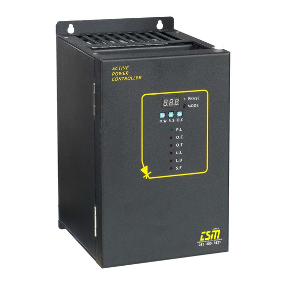
Page 10: Explanation Of Product External Form, Use Terminology And Function
Explanation of product external form, use terminology and function Explanation of product external form, use terminology and function • ▷ PHASE : 3 colors Light Emitting Diode, electric current value indication of each phase. RED : R-Phase , Yellow : S-Phase, Green : T-Phase White : Average nominal current value ▷... -
Page 11: Apc-Tf Series Mode Select On The Pcb
APC-TF Series Mode select on the PCB • Place of mode select switch on the PCB Signal SELECT SWITCH controll power terminal block The fan or power supply of 220V AC RESET SWITCH must be connected. 3PIN center terminals are F.G terminals. - Page 12 APC-TF Series users terminal block wiring diagrams 4 – 20mA Potentio meter AUTO/MANUAL RUN/STOP Reset Alarm relay ① ② ③ ④ ⑤ ⑥ ⑦ ⑧ ⑨ ⑩ ⑪ ⑫ ⑬ ⑭ + - OPEN : Stop Push button switch CLOSE : Running...
- Page 13 APC-TF Series Automatic operation wiring diagrams • Automatic operation mode : External input wiring from TIC 4 – 20mA Potentio meter AUTO/MANUAL RUN/STOP Reset Alarm relay ① ② ③ ④ ⑤ ⑥ ⑦ ⑧ ⑨ ⑩ ⑪ ⑫ ⑬ ⑭...
- Page 14 APC-TF Series Automatic with remote control operation wiring diagrams • Automatic with remote control mode : Control by external input wiring from TIC and external potentio meter. 4 – 20mA Potentio meter AUTO/MANUAL RUN/STOP Reset Alarm relay ① ② ③ ④ ⑤ ⑥ ⑦ ⑧ ⑨ ⑩ ⑪ ⑫ ⑬ ⑭...
- Page 15 APC-TF Series Manual operation wiring diagrams • Manual operation mode : The “PW” potentio meter sets a limit on available power from the SCR Power Controller. The adjustment range is 0 to 100% of the units rating. 4 – 20mA...
- Page 16 APC-TF Series Manual with remote control operation wiring diagrams •Manual with remote control mode : Control by external potentio meter set-point value with “P.W” potentio meter setting up value. 4 – 20mA Potentio meter AUTO/MANUAL RUN/STOP Reset Alarm relay ① ② ③ ④ ⑤ ⑥ ⑦ ⑧ ⑨ ⑩ ⑪ ⑫ ⑬ ⑭...
- Page 17 APC-TF Series ON/OFF control operation wiring diagrams •ON/OFF control mode : The “PW” potentio meter sets a limit on available power from the SCR Power Controller. The adjustment range is 0 to 100% of the units rating. 4 – 20mA Potentio meter AUTO/MANUAL RUN/STOP...
-
Page 18: Apc-Tf Series Commissioning Procedure
APC-TF Series COMMISSIONING PROCEDURE Read this chapter carefully before commissioning the controller COMMISSIONING PROCEDURE - SAFETY ⊙ CHECKING THE CHARACTERISTICS AND WIRING ① Confirm so that all wiring is suitable to an utility purpose electing normally by final vote. ② Before connection to the load as following ;... - Page 19 APC-TF Series Operation and L.E.D information • PILOT LED : Green color * Running : Over a control output value 0 %, lighting hold Control output value 0 %, lighting off * Stop : Lighting off * Input signal error (4-20mA) : 1 second cycle lighting blink * P.W value 0 % : 2 second cycle lighting blink...
- Page 20 APC-TF Series Operation and L.E.D information • UNLOAD LED : Red color - White : Normal running condition - Blinking : Unload (heat element be cut or at short) sensing and during the make an analysis about 10 second. - Lighting : Unload determination ①...
-
Page 21: Apc-Tf Series Maintenance - Fuses
APC-TF Series MAINTENANCE - Fuses DANGER! The controller must be maintained by personnel qualified and trained to work with low voltage electrical equipment in an industrial environment. The user’s installation must be protected upstream (non high-speed fuses, thermal or electromagnetic circuit breaker, suitable fuse-isolator) and must comply with current standards. -
Page 22: Thyristor Protection
For the use of high-speed fuses in short-wave infrared applications, Please contact Controls. To protect the thyristors in the APC-TF series, 3 fuses and bus-bar must be used. Details of these are given in the following table. Nominal current Dimensions... - Page 23 DANGER! If failure happens of the SCR, must be change to compatible maker’s. To control the thyristors in the APC-TF series, 3 SCRs and bus-bar must be used. Details of these are given in the following table for compatible maker.
-
Page 24: Apc-Tf Series Servicing
APC-TF Series SERVICING APC-TF Series controllers must be mounted with the heatsink positioned vertically, with no obstructions above or below which could inhibit or impede airflow. Attention! If several units are mounted in the same cabinet, they should be arranged in such a way that air expelled from one cannot be drawn into the unit located above it.
Need help?
Do you have a question about the APC-TF Series and is the answer not in the manual?
Questions and answers