
Related Manuals for AND HV-15KC


Summary of Contents for AND HV-15KC
- Page 1 Digital Platform Scale HV-15KC HV-15KCP HV-60KC HV-60KCP HV-200KC HV-200KCP HW-10KC HW-10KCP HW-60KC HW-60KCP HW-100KC HW-100KCP HW-200KC HW-200KCP 1WMPD4003471...
- Page 2 No part of this publication may be reproduced, transmitted, transcribed, or translated into any language in any form by any means without the written permission of A&D Company Ltd. The contents of this manual and the specifications of the instrument covered by this manual are subject to change for improvement without notice.
-
Page 3: Table Of Contents
6. DESCRIPTION OF EACH PART .................13 6.1. Display and Symbols ....................14 6.2. Keys..........................16 7. BASIC OPERATION ....................18 7.1. Turning the Scale on/off and Weighing ..............18 7.1.1. When Using the AC Adapter................18 7.1.2. Type C with Batteries..................19 7.2. Tare (And Net Display) .....................20 7.2.1. - Page 4 10.2. Entering the comparator values ................27 AUTO-TARE ......................29 11.1. Built-in Printer for HV/HW-CP Series ..............30 ID NUMBER AND GLP .....................32 12.1. Setting the ID number ..................32 12.2. Setting the clock.....................33 12.3. GMP report ......................34 CALIBRATION (ADJUSTING THE SCALE) .............38 13.1.
-
Page 5: Compliance
Please note that this equipment generates, uses and can radiate radio frequency energy. This equipment has been tested and has been found to comply with the limits of a Class A computing device pursuant to Subpart J of Part 15 of FCC rules. These rules are designed to provide reasonable protection against interference when this equipment is operated in a commercial environment. -
Page 6: Outline And Features
The comparator function compares the displayed weight value with the upper limit value (HI) and the lower limit value (LO) and displays the result. The result can be output by a buzzer if option HVW-04CJA is installed. -
Page 7: Precautions
Do not install the scale near equipment which produces magnetic fields. Do not install the scale where there is apt to be static electricity, in a place where the relative humidity is lower than 45% RH. Plastic and isolators are apt to be charged with static electricity. -
Page 8: Installing The Scale
Step 6 needs calibration, refer to "14. Calibration". - The display unit can be adjusted in four steps in the up-and-down direction. Setting the display sideways is also possible. (Make sure that the pole is secured at the lower part of the pole using the allen screws. Do not turn the display unit at a joint for the pole.) -
Page 9: Unpacking
Refer to "Accessries List" on page 8. Accessories supplied depend on the scale model. AC adapter Please confirm that the AC adapter type is correct for your local voltage and receptacle type. Base Unit Display unit cover 14:3003217 Caution Do not pull the load cell cable. -
Page 10: Accessories And Options List
Type C/CP Type C AC adapter Batteries (Not included) Please confirm that the main power type or AC adapter type is correct for your local voltage and receptacle type. 5.1. Accessories and Options List Accessories List Type Models Accessories (Quantity) - Page 11 Roller conveyor for HV-60KC and HW-60KC RS-232C cable, D-sub 25 pin, 2 m AX-KO2466-200 RS-232C cables are also available in lengths of 5 and 10 m. Note OP-16 is factory-installed. For handling HVW-11C, 13 and 14, refer to the relevant option manual.
-
Page 12: Installing The Batteries For Type C
Caution Replace used batteries with four new ones, when “lb” is displayed. Do not mix used and new batteries. It may cause damage to the batteries or the scale, if used. Check the battery direction. If the batteries are installed in the wrong direction, it may cause battery leakage. -
Page 13: Removing The Pole
When removing the load cell cable, do not pull on the load cell cable connector forcibly and do not pull on the wires of the cable. Do not bend the cable forcibly. Use care so that the load cell cable does not touch the pan inside the base unit. -
Page 14: Grounding The Scale
When using where there may be static electricity, ground the scale. The grounding procedure depends on the scale model. Refer to the table below. These procedures are only for grounding part of the scale. Models Refer to HV-15KC/HV-15KCP/ HW-10KC/HW-10KCP Procedure A HV-60KC/HV-60KCP/HV-200KC/HV-200KCP Procedure B HW-60KC/HW-60KCP/HW-100KC/HW-100KCP/HW-200KC/HW-200KCP... -
Page 15: Description Of Each Part
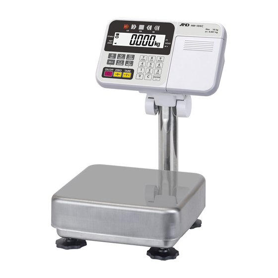
6. Description of Each Part Display Unit Display Unit Models Models HV-60KC HV-60KCP HV-15KC HV-200KC HV-200KCP HV-15KCP HW-60KC HW-60KCP HW-10KC HW-100KC HW-100KCP HW-10KCP HW-200KC HW-200KCP Pole Pole Pan (Weighing Pan) Base Unit Leveling Foot Type C Type CP Leveling Foot... -
Page 16: Display And Symbols
Weighed mass value unit Zero point (Example) STABLE When the key is pressed with nothing on the pan, ZERO the zero point mark and the stability mark are displayed. ZERO Page 14 HV/HW-C/CP Series... - Page 17 Check the base unit and the weighing pan. The "digit" is a unit of display, and is equivalent to the minimum measurable mass. The " nearly-zero " or zero band is within ±5 digits from zero point in the unit of kg.
-
Page 18: Keys
ZERO scale displays the mass value of zero and the zero point mark. If the scale is in tare in this time, the tare value is cleared. When accumulation is displayed, the accumulation is cleared. - Page 19 Display and Symbols Description SET key When setting the upper/lower limit, switch between + and -. Press Enters preset tare setting mode press hold Press Performs paper feed at the built-in printer press hold Press Displays the accumulated results press...
-
Page 20: Basic Operation
7.1.1. When Using the AC Adapter Step 1 Ground the scale. Step 2 Confirm that nothing is placed on the pan. Step 3 Confirm that local voltage and receptacle type are correct. Step 4 The scale turns on/off using the key alternately. -
Page 21: Type C With Batteries
Replace used batteries with four new ones when “lb” is displayed. Battery life depends on the ambient temperature. Remove the batteries from the display unit when the scale is not to be used for a long time. The batteries may leak and cause damage. HV/HW-C/CP Series Page 19... -
Page 22: Tare (And Net Display)
Step 3 Place an article to be weighed into the container. Wait for the stability mark to be displayed and read its net display. Step 4 Remove the article and the container from the pan. 7.2.2. Digital Input (Preset Tare) -
Page 23: Switchimg The Mode
HV-15KC, HV-15KCP, HW-10KC and HW-10KCP Number of Accumulation accumulations *1 value *1 Upper/lower limit values setting mode Preset tare setting mode * The scale displays the number of accumulations and an accumulation value only when accumulation data exists. HV/HW-C/CP Series Page 21... -
Page 24: Counting Mode
Pressing the key, after is displayed, lo ut MODE displays the next unit. Note Step 6 Remove the samples and the container from the pan. The pan shape depends on the scale model. Page 22 HV/HW-C/CP Series... -
Page 25: Counting The Number Of Articles
Step 4 Place articles in the container. Wait for the stability mark to be displayed and read the count. STABLE Step 5 Remove the articles and the container from the pan. Note The pan shape depends on the scale model. -
Page 26: Accumulation Function
The "nearly-zero" is within ±5 digits from the zero point in the unit of kg. The "digit" is a unit of display, and is equivalent to the minimum measurable mass. The "zero point" is the fundamental starting point to weigh anything. - Page 27 Function table Description When the display is a positive stable value and not nearly-zero, the scale accumulates the data automatically. The next accumulation 5um 3 can be performed after the display becomes nearly-zero or a negative value. When the display is a stable value and not nearly-zero, the scale accumulates the data automatically.
-
Page 28: Comparator
Five-level, three-level and seven-level (portion weighing mode) comparators are available. Each comparator mode compares the weight value against the preset limit values and outputs the results using LEDs (yellow / green / red). When the optional comparator relay output (HVW-04CJA) is installed, the results are output as a relay signal. -
Page 29: The Formula To Compare
10.2. Entering the comparator values 1. In the weighing mode, press and hold the SET key and press COMP key to enter the comparator value setting mode. 2. Enter the comparator values using the following keys. - Page 30 To switch between + and - ENTER To store setting values * Each time the SET key is pressed, “-” switches between being lit and off at the first digit. “-”being lit means a minus setting. 3. When the setting is complete, “...
-
Page 31: Auto-Tare
” is selected, the scale will tare the initial (container) weight automatically. When all load on the weighing pan is removed, the scale will return to the zero point and the tare weight will be automatically cleared. If the scale does not return to the zero point, press the key to clear the tare weight. -
Page 32: Built-In Printer For Hv/Hw-Cp Series
AX-PP147-S (set of 5 rolls) Operation and Print Samples Press and hold the SET key and press the PRINT key. Paper feed is performed. The following example is when the print mode in the function settings is selected. Printing example for prtp 1~8 ←Weight... - Page 33 Installing the roll paper Step 1 Pull the printer cover toward you to open. Step 2 Install the roll paper so that the end of the paper is at the top. Step 3 Close the printer cover. Step 4 When the roll paper is installed successfully, the built-in printer automatically feeds out the paper.
-
Page 34: Id Number And Glp
The “Start block” and “End block” for GLP data 12.1. Setting the ID number Step 1. With the power turned OFF, press and hold the TARE key and press the ON/OFF key to turn the power ON and enter the function setting mode. -
Page 35: Setting The Clock
12.2. Setting the clock The clock can only be set for built-in printer models (-CP models). Step 1 Turn off the display. Press and hold the TARE key and press the ON/OFF key to turn on the display and enter Press several function setting mode. -
Page 36: Gmp Report
To print the GMP report to an AD-8127 printer, select the function setting “inf1 1” and “inf2 1” and use MODE 3 of the printer. To output the GMP report to a personal computer, select the function setting “inf1 1”... - Page 37 The calibration test mode is used to compare a calibration weight with the calibration test data weighed by the scale. This test does not perform calibration. Step 1. In the weighing mode, press and hold the CAL switch until CC appears, and release the switch.
- Page 38 Output of “Title block” and “End block” ZERO When weight values are recorded as the GMP report, “Title block” and “End block” are added at the beginning Press and at the end of a group of weight values. and hold Title block Step 1.
- Page 39 End block Press Step 3. Press and hold the PRINT key until and hold recend appears, and release the key. The scale outputs the “End block.” End block To output the " " Step 4. The scale automatically returns to the weighing mode.
-
Page 40: Calibration (Adjusting The Scale)
13. Calibration (Adjusting the Scale) The scale is an instrument which weighs the "weight" and displays its "mass". Calibration is the adjustment function so that the scale can weigh correctly. Three steps of calibration are available Gravity Acceleration Correction ... The function to correct the scale’s local gravity... -
Page 41: Gravity Acceleration Table
13.1. Gravity Acceleration Table Amsterdam 9.813 m/s Manila 9.784 m/s Athens 9.800 m/s Melbourne 9.800 m/s Auckland, NZ 9.799 m/s Mexico 9.779 m/s Bangkok 9.783 m/s Milan 9.806 m/s Birmingham 9.813 m/s New York 9.802 m/s Brussels 9.811 m/s Oslo 9.819 m/s Buenos Aires 9.797 m/s... -
Page 42: Complete Calibration Procedure
MODE correction mode. Press the key to make the ENTER numerical value blink and proceed to input mode. Enter using numerical keypad Step 3 Set your local gravity acceleration using the numerical keypad. Step 4 Press the key to store the new value. -
Page 43: Calibration Of The Zero Point
11. Wait for the stability mark to be Stability mark displayed. Press the key. ENTER The scale then calculates the span and stores it. Step 13 The scale displays fter displaying to finish setting. Remove the mass from the pan. -
Page 44: Function Table
14. Function Table The function table is used to store and refer items that determine the performance of the scale. Each item has a parameter. The parameters are stored in the scale even if the power is removed. Item Parameter 14.1. -
Page 45: Parameter List
Parameter Details and usage Functions with all the keys Key lock ■ lock Functions with the ON/OFF, ZERO, TARE, HOLD, M+ and PRINT key Functions with the ON/OFF, ZERO, TARE key ■ Automatic power After 5 minuets After 10 minuets... - Page 46 PRINT HOLD Five-level comparator Comparator ■ judgment value Three-level comparator (upper and lower limits) Cp-l Seven-level comparator (portion weighing) : factory settings ■ "Nearly-zero" is within ±5 digits (five times the minimum mass that can be weighed) from zero point in the unit kg.
- Page 47 ■ Outputs data at auto print setting, +5 digits or more and stabilization (commands) Outputs data at auto print setting, +5 digits or more, or -5 digits or less and stabilization (commands) Outputs data at auto print setting, +5 digits or more and stabilization when the...
-
Page 48: Factory Settings
■ Outputs data at auto print setting, +5 digits or more and stabilization (commands) Outputs data at auto print setting, +5 digits or more, or -5 digits or less and stabilization (commands) Outputs data at auto print setting, +5 digits or more and stabilization when the comparator... - Page 49 ■ Prints data at auto print setting, +5 digits or more and stabilization Prints data at auto print setting, +5 digits or more, or -5 digits or less and stabilization Prints data at auto print setting, +5 digits or more and stabilization when...
-
Page 50: Options
OP-ch3: HVW-04C 15.1. Installing an option Remove the two M3 screws at both side on the panel, and then remove the panel from the display unit. Connect the cable located inside the display unit to the connector on the option panel. -
Page 51: Hvw-03C Rs-232C Interface
→ Request to send ← Clear to send → 9 - - Used internally Names other than TXD and RXD are for the DTE side. External Scale side device (DCE) side (DTE) Approx.5V Terminal example of the external Inside of the scale... -
Page 52: Hvw-04C Comparator Relay Output / Buzzer / Contact Input
4 Relay output LO 5 Relay output LOLO 6 Relay common COM LOLO Inside of Solid sate relay HV/HW-C/CP Terminal names and wiring example of external contact input plug External contact input plug 3.5mm stereo mini-plug or equivalent Con1 line Con2 terminal... -
Page 53: Communication Format
Stable weighing data Stable counting data Unstable weighing data Out of weighing range The data consists of 9 characters including the polarity and decimal point. There are 5 units. _ k g: Weighing mode “kg” _ l b: Weighing mode “lb”... -
Page 54: Command Mode
When the weight display is stable at +5d (d = minimum display in kg) and above, the data is sent. The next transmission can not occur until after the weight display falls +4d or below. prt1 6 Auto-print mode +/- data ( When the weight display is stable at ±5d (d = minimum display in kg) and above +5d... - Page 55 When the five-level comparator mode is used: Not used Set the six-digit value excluding When the three-level comparator mode is used: the polarity and decimal point Not used When the seven-level comparator mode is used: Set the level 5 upper limit value.
- Page 56 Command Description Remarks When the five-level comparator mode is used: Set the HIHI limit value. When the three-level comparator mode is used: Set the HI limit value. When the seven-level comparator mode is used: Set the level 4 upper limit value. When the five-level comparator mode is used: Set the HI limit value.
- Page 57 Tare the scale. (No reply for the function setting “5if1 0 “.) Command Reply The scale is in a condition that tare operation is possible. Switch the weighing unit. (No reply for the function setting “5if1 0 “.) Command Reply Five-level comparator mode…Not used...
- Page 58 Three-level comparator mode…Not used Seven-level comparator mode…Set the level 5 upper limit value. (No reply for the function setting “5if1 0 “.) Set the six-digit value excluding the polarity and decimal point. Command + 0 0 0 5 0 0 C...
- Page 59 . Then, the scale will reply “?”. HV/HW-C/CP series Command Reply The scale received an undefined command. When the function setting “5if1 0 “ is selected, undefined commands are ignored and no reply is sent. HV/HW-C/CP Series Page 57...
-
Page 60: Using Ufc (Universal Flex Coms) Function
The UFC function allows you to print out as you format the printer (UFC format). The scale can store the UFC format as text data. It will include parameters to replace with the count data, weight data and so on. The maximum number of text data is 300 characters. - Page 61 Parameters for the scale data will be replaced by the format below when the scale sends them out. Data has a fixed number of digits including a sign and a decimal point. The insignificant zeros are replaced by “Space (20H)” (except the ID number).
- Page 62 $SP 3,$TM,$CR,$LF,& 12:34:56 $CR,$LF,& A&D HV-15KC ‘ A&D HV-15KC’,$CR,$LF Terminator codes "~" shows "Space.". Normally the printer needs to receive the terminator, and do not forget to add the terminator code(s) to the end of text data. Page 60 HV/HW-C/CP Series...
-
Page 63: Specifications
60Hz) A Approximately 1200 hours Battery life (HV-C) A (When using alkaline battery and setting the display to off) Ambient temperature and humidity -10° C to 40° C, Less than 85%R.H. (Do not allow condensation) A Weighing pan size [mm]... - Page 64 60Hz) A Approximately 1200 hours Battery life (HW-C) A (When using alkaline battery and setting the display to off) Ambient temperature and humidity -10° C to 40° C, Less than 85%R.H. (Do not allow condensation) A Weighing pan size [mm]...
- Page 65 Dimensions Models HV-15KC HV-15KCP HW-10KC HW-10KCP O 42.7 1 80 1 80 Models HV-60KC HV-60KCP HW-60KC HW-60KCP O 42.7 1 87 Unit: mm HV/HW-C/CP Series Page 63...
- Page 66 Models HV-200KC HV-200KCP HW-100KC HW-100KCP HW-200KC HW-200KCP O 42.7 1 87 Unit: mm Page 64 HV/HW-C/CP Series...
-
Page 67: Maintenance
17. Maintenance Refer to "3. Precautions" for use. Refer to "6.1. Display and Symbols " for displayed error code. Refer to "13. Calibration (Adjusting the Scale)" for precision weighing. Periodically check the accuracy of the weighing. Calibrate the scale, if it has been moved to another location or the environment has changed. - Page 68 MEMO Page 66 HV/HW-C/CP Series...
- Page 69 MEMO HV/HW-C/CP Series Page 67...
- Page 70 MEMO Page 68 HV/HW-C/CP Series...
- Page 71 3-23-14 Higashi-Ikebukuro, Toshima-ku, Tokyo 170-0013, JAPAN Telephone: [81] (3) 5391-6132 Fax: [81] (3) 5391-6148 A&D ENGINEERING, INC. 1756 Automation Parkway, San Jose, California 95131, U.S.A. Telephone: [1] (408) 263-5333 Fax: [1] (408)263-0119 A&D INSTRUMENTS LIMITED Unit 24/26 Blacklands Way, Abingdon Business Park, Abingdon, Oxfordshire OX14 1DY United Kingdom Telephone: [44] (1235) 550420 Fax: [44] (1235) 550485 A&D AUSTRALASIA PTY LTD...
Need help?
Do you have a question about the HV-15KC and is the answer not in the manual?
Questions and answers