Table of Contents
Advertisement
Quick Links
page 1 of 36
Technology for Vacuum Systems
Instructions for use
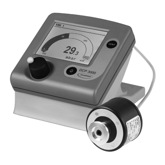
DCP 3000
Vacuum gauge
Documents are only to be used and distributed completely and unchanged. It is strictly the users´ responsibility to check carefully
the validity of this document with respect to his product. Manual-no.: 999162 // 19/01/2011
Advertisement
Table of Contents

Related Manuals for vacuubrand DCP 3000


Summary of Contents for vacuubrand DCP 3000
- Page 1 1 of 36 Technology for Vacuum Systems Instructions for use DCP 3000 Vacuum gauge Documents are only to be used and distributed completely and unchanged. It is strictly the users´ responsibility to check carefully the validity of this document with respect to his product. Manual-no.: 999162 // 19/01/2011...
- Page 2 Every VACUUBRAND device achieves the specifications. We are committed to providing our customers with this high quality standard. We know that the device cannot replace all of your real work and hope that our products contribute to an effective and trouble-free realisation of your work.
-
Page 3: Reset / Language Selection
page 3 of 36 Reset / Language selection press both switch off D C P 300 0 V 2. 0 D eut s ch P ort u guê E ngl i sh Ρ yccк ий Fra nçai s P ol ski I t al i ano N eder l . -
Page 4: Table Of Contents
(US-Reg.No 3,733,388) and also the shown ® ® company logos are trademarks of VACUUBRAND GMBH + CO KG in Germany and/or other coun- tries. Documents are only to be used and distributed completely and unchanged. It is strictly the users´ responsibility to check carefully... -
Page 5: Safety Information
5 of 36 Safety information General information To operate the vacuum gauge DCP 3000, at least one external pressure transducer VSK 3000 or VSP 3000 or MPT 100 is required! Read and comply with this manual before installing or operating the equip- NOTICE ment. -
Page 6: Ambient Conditions
page 6 of 36 • Comply with max. permitted ambient and gas temperature (see ”Technical data”) and make sure ventilation is adequate if the equipment is installed in a housing or if ambient temperature is elevated. • Avoid high heat supply (e.g., due to hot process gases). • In case of residues or aggressive or condensable media install a gas washing bottle if necessary. -
Page 7: Maintenance And Repair
page 7 of 36 Operation with pressure transducer VSP 3000: ☞ Attention: Maximum pressure reading: 1*10 mbar. Pressure values above 1000 mbar can not be displayed. Danger of unnoticed overpressure! Risk of burst- ing! Operation with pressure transducer MPT 100: ☞ See instructions for use of MPT 100. • Use only genuine spare parts and accessories. Otherwise safety and perform- ance of the equipment as well as the electromagnetic compatibility of the equip- ment might be reduced. -
Page 8: Technical Data
8 of 36 Technical data Technical data of display unit Display unit DCP 3000 Display illuminated LCD graphic display Pressure units / scale (selectable) mbar, Torr or hPa Ambient temperature range (operation) 10°C to +40°C Ambient temperature range (storage) -10°C to +70°C Permitted relative atmospheric moisture during 30% to 85% operation (no condensation) Maximum permissible range of supply voltage 24 V= ( ±6V ) -
Page 9: Technical Data Of Pressure Transducers Vsk 3000 And Vsp 3000
page 9 of 36 Technical data of pressure transducers VSK 3000 and VSP 3000 Type VSK 3000 VSP 3000 ceramic diaphragm (alumina), thermal conductivity according to Measuring principle capacitive, absolute pressure, Pirani, dependent on gas type gas type independent 1060 mbar - 0.1 mbar 1*10 mbar - 1*10 mbar Measuring range (absolute) -
Page 10: Wetted Parts
page 10 of 36 Wetted parts Components Wetted materials VSK 3000 Sensor aluminium oxide ceramics Sensor housing, measurement chamber PPS, glass fibre Seal at sensor chemically resistant fluoroelastomer Hose nozzle Clamping ring Small flange stainless steel VSP 3000 Sensor aluminium oxide ceramics Sensor housing, measurement chamber, small PBT, glass fibre / PUR flange Hose nozzle / O-ring PPS, glass fibre / FPM We reserve the right for technical modification without prior notice! Documents are only to be used and distributed completely and unchanged. -
Page 11: Use And Operation
page 11 of 36 Use and operation Assembling the country specific mains plug ☞ The wall power supply is delivered with mains plugs for Europe, UK, USA and Australia. ☞ To replace the mains plug press the locking key and re- move mains plug. ☞... - Page 12 • Pressing longer than 2 seconds vents the system to atmospheric pressure. on/off switch selection knob • Press to reach the set-up menu of the function • Turn to reach the parameter set-up • Press to reach the set value • Turn to change the set value • Press to confirm and to reach further parameters or to exit the set-up menu Rear side DCP 3000 connection power supply sockets for connection serial interface of external pressure RS 232 C transducer and/or venting valve rating plate Attention: Do not cant when assembling or removing plug connections! Comply with correct positioning of the plug.
-
Page 13: Changing The Vacuum Connector At Pressure Transducer Vsk 3000
page 13 of 36 Changing the vacuum connector at pressure transducer VSK 3000 Installing the hose nozzle: Unscrew the flange (using a 17 mm open-end wrench, if necessary) to expose the compression fitting (1). Slip the compression nut, and then the ferrule, onto the smooth end of the supplied hose nozzle (2). Slide the smooth end of the hose nozzle onto the compression fitting on the VSK 3000 gauge head, and tighten the compression nut firmly finger-tight (3). Installing the PTFE-tubing connection (PTFE-tubing ID: 8mm, OD: 19mm): Unscrew the flange (using a 17 mm open-end wrench, if necessary) to expose the compression fitting (1). - Page 14 Readout of the pressure transducer via VACUU•BUS line by the vacuum gauge DCP 3000 using VACUU•BUS protocol. Maximum cable length inside buildings: 30m (extension cable VACUU•BUS 2m: order-no. 612552 / extension cable VACUU•BUS 10m: order-no. 2618493). Don’t use more than one DCP 3000 within a VACUU•BUS system. More than one DCP 3000 within the same VACUU•BUS system will interfere with each other and cause error messages of the connected components. Documents are only to be used and distributed completely and unchanged. It is strictly the users´ responsibility to check carefully...
- Page 15 page 15 of 36 Prior to use ➨ Connect the gauge head VSK 3000 or VSP 3000 with connecting cable (VACUU•BUS line) to a socket at the rear side of the DCP 3000. ➨ Connect the gauge head to the vacuum chamber via the small flange connection, the hose nozzle or PTFE tubing. Avoid contamination (oil/oil mist) of the gauge head when generating the vacuum with an oil-filled vacuum pump. ☞ Do not mount the gauge head directly at the oil-sealed pump. The diameter of the pipelines should be as large as possible.
-
Page 16: Menu
page 16 of 36 Menu VSK 1 VSP 1 pressure indication pressure indication with VSK 3000 with VSP 3000 1013 mbar mbar RS-232 Configuration Display Baud 19200 Adjustment 1000 mbar Brightness 100% Parity 8-N-1 RS-232 . . . Contrast 40% Handshake RTS-CTS Sensors . . . Sound Off Send... -
Page 17: Configuration
page 17 of 36 Configuration In the menu ”Configuration” the device parameters are set. Settings ☞ Select the parameters via the selection knob. ➨ Switch the DCP 3000 on. ➨ Press the selection knob. ➨ Turn the selection knob to choose a menu and confirm by pressing the selection knob. ’’Configuration’’ Settings for • Adjustment (of the pressure transducer) • RS-232 (serial interface) • Sensors (configuration and switching between several pressure transducers) • Display (brightness and contrast of the display, language, sound,..) • Setpoint (valves, digital I/O interface) • Log Data (Off, 1 . . . 3600 seconds) • Graphic ☞ Adjustment: Adjustment of the pressure transducer under vacuum and/or at atmospheric pressure, see section ”Adjustment of pressure transducer VSK 3000 / VSP 3000”. - Page 18 page 18 of 36 The screen-shot shows the factory-set values. Configuration Adjustment 1000 mbar RS-232 . . . Sensors . . . Display . . . Setpoint . . . Log data Off - - - - - - Graphic - - - - - - - - - - - - Back - - - - - - - - Documents are only to be used and distributed completely and unchanged.
-
Page 19: Connecting Several Pressure Transducers
page 19 of 36 Connecting several pressure transducers It is possible to connect several external pressure transducers simultaneously to the DCP 3000. Maxi- mum number of pressure transducers of the same type (VSK 3000 or VSP 3000) connected to one DCP 3000: four. Alternatively connect 1 x MPT 100 instead of one VSP 1000 from DCP 3000 software version 2.03 or 4 x MPT 100 instead of VSP 1000 from DCP 3000 software version 2.22. That is a total of eight external pressure transducers at maximum. Up to four additional pressure transducers VSK 3000 may be connected as reference if configured accordingly (see ”Measuring differential pressure”). Only the reading of one pressure transducer is displayed at a time. ☞ The VACUU•BUS address of the active and displayed pressure transducer is shown in the upper left corner (status line). -
Page 20: Measuring Differential Pressure
page 20 of 36 Measuring differential pressure A differential pressure between two pressure transducers can only be determined and indicated be- tween two pressure transducers VSK 3000 connected to the DCP 3000. ☞ This requires one of the two pressure transducers to be defined as reference (e.g., VACUU•BUS ad- dress ”Ref. 1”). ☞ In addition, both pressure transducers have to be configured to corresponding VACUU•BUS ad- dresses (VSK x and Ref. x). If the two addresses do not correspond (VSK x and Ref. y), no differen- tial pressure will be determined or displayed. Then it is necessary to reconfigure the address of one pressure transducer to enable differential pressure measurement (see section ”Reconfiguring the pressure transducer”.) ➨ The displayed pressure value is: (”pressure value of Ref. x” minus ”pressure value of VSK x”) mbar... -
Page 21: Setpoints
21 of 36 Setpoints Valves (see accessories) can be used after appropriate configuration to set setpoints to open or close a valve. The digital I/O interface can be used as interface for existing (provided by the customer) isolation, cool- ant or venting valves or a VACUUBRAND VMS module, if these components are not equipped with a VACUU•BUS connection. The component has to be connected to the output of the module (an addi- tional voltage supply is necessary). Each valve / digital I/O interface can be used to set a setpoint “On” and a setpoint “Off”. The setting range depends on the measuring range of the pressure transducer. -
Page 22: Interface Parameters
page 22 of 36 Interface parameters The DCP 3000 is equipped with a serial interface (RS 232C, nine-pole Sub-D-plug). ☞ Plug-in or remove the cable (cable RS 232C) from the interface only if the equipment is switched off. ☞ The interface is not electrically isolated from the measuring circuit. ☞ For optimal electromagnetic compatibility assemble an interface filter (cat. no.: 638235). ☞ The serial interface is prepared for the connection of a commercial Bluetooth adapter for wireless communication (current supply for Bluetooth adapter on pin 9, see ”Connector assignment”). ☞ Settings via interface are stored. Setting the interface Set the interface parameters directly at the DCP 3000. The factory set values are underlined. Edit and confirm the interface parameters in the function ”Configuration” in the menu ”RS-232” using the selection knob. -
Page 23: Notes Concerning The Function Data Logger (Recording And Sending Of Data)
page 23 of 36 Notes concerning the function data logger (recording and sending of data) • Maximum number of recordable readings is 32765. • During recording the runtime is displayed. • The data of all connected pressure transducers are recorded, i.e. for two pressure transducers maxi- mum 16382 readings per pressure transducer are recorded. • Recording starts, if ”Log data” is set to 1 ..3600 seconds (see menu ”Configuration - Log data”) and stops if ”Log data” is set to ”Off” or the device is switched off. • If the recording interval is changed, stored readings are deleted and recording starts again. • After power failure the recording interval is set to ”Off”, the stored readings can be read out further • ”Graphic” (with or without function ”log data”) displays maximum 240 readings of the selected pres- sure transducer. • If ”Graphic” with function ”log data” is selected it is possible to extend the time scale to the next inter- val if the displayed time scale is reached by turning the selection knob. -
Page 24: Read Commands
page 24 of 36 Read commands Command Response Description Function XXXX.X mbar/Torr/hPa unit according to preselections actual pressure IN_PV_1 X.XXE±X mbar/Torr/hPa XXXX.X mbar/Torr/hPa pressure of pressure transducer x (or- pressure IN_PV_Sx X.XXE±X mbar/Torr/hPa der of numbering like display in menu ”Sensors” XXXX.X XXXX.X ...mbar pressure of all connected pressure IN_PV_X X.XXE±X mbar/Torr/hPa... - Page 25 page 25 of 36 Function Command Response Description IN_SP_11 XXXX.X mbar/Torr/hPa setpoint On 1 Setpoint X.XXE±X mbar/Torr/hPa setpoint On 2 setpoint On 3 setpoint On 4 IN_SP_21 XXXX.X mbar/Torr/hPa setpoint Off 1 X.XXE±X mbar/Torr/hPa setpoint Off 2 setpoint Off 3 setpoint Off 4 Documents are only to be used and distributed completely and unchanged. It is strictly the users´ responsibility to check carefully the validity of this document with respect to his product.
-
Page 26: Write Commands
page 26 of 36 Write commands Parameter Description Function Command XX:XX time OUT_SP_1 time interval for automatic sending of all pressure values mm:ss alternatively XX:XX OUT_SP_2 time interval for recording* OUT_VENT 0: venting valve closed 1: venting valve open 2: venting until atmospheric pressure OUT_SENSOR 1-8 external sensors (if connected) REMOTE switch off device switch on device setpoint On 1 XXXX.X mbar/Torr/hPa OUT_SP_11... -
Page 27: Troubleshooting
page 27 of 36 Troubleshooting Fault Possible cause Remedy ❑ No display. ➨ ✔ Power supply (wall plug) not Plug in power supply, con- plugged in, no power avail- nect cable of power supply able? (wall plug) to DCP 3000. Switch on device. Check mains fuse. ➨ ✔ DCP 3000 switched off? Switch device on. ➨... -
Page 28: Accessories
Digital-I/O-Module VACUU•BUS (fault indicator) .................636228 Analog-I/O-Module VACUU•BUS (analog voltage output of vacuum reading) ...................636229 PC-Software VACUU•CONTROL ....................692920 Conversion of a VACUUBRAND valve with diode plug to a VACUUBRAND valve with VACUU•BUS plug: VACUUBRAND valve with diode Conversion kit ”valve cable with plug VACUU BUS plug”... -
Page 29: Cleaning The Pressure Transducers
➨ Allow the pressure transducer to dry. ➨ Readjust the pressure transducer if necessary. Calibration in the factory Control of measuring equipment The VACUUBRAND DKD calibration laboratory is accredited by the Physikalisch-Technische Bunde- sanstalt (PTB; German national institute for science and technology and the highest technical authority of the Federal Republic of Germany for the field of meteorology and certain sectors of safety engineer- ing) for the measurable variable pressure in the pressure range from 10... -
Page 30: Readjustment Of Pressure Transducer Vsk 3000
page 30 of 36 Readjustment of pressure transducer VSK 3000 NOTICE The pressure transducer VSK 3000 was adjusted using factory standards, which are traceable through regular calibration in an accredited laboratory (German Calibration service) to the German national pressure standard. Depending on the process and/ or on accuracy requirements, check the adjustment and readjust if necessary. For readjustment, the device has to be adjusted both at atmospheric pressure as well as under vacuum. For readjustment the reference pressures have to be known pre- cisely. In the range between 20 and 700 mbar no adjustment is possible; ---- mbar is displayed. -
Page 31: Readjustment Of Pressure Transducer Vsp 3000
page 31 of 36 Readjustment of pressure transducer VSP 3000 NOTICE The pressure transducer VSP 3000 was adjusted using factory standards, which are traceable through regular calibration in an accredited laboratory (German Calibration service) to the German national pressure standard. Depending on the process and/ or on accuracy requirements, check the adjustment and readjust if necessary. For readjustment, the device has to be adjusted both at atmospheric pressure as well as under vacuum. -
Page 32: Notes On Return To The Factory
page 32 of 36 Notes on return to the factory Repair - return - DKD calibration Safety and health of our staff, laws and regulations regarding the handling of dan- NOTICE gerous goods, occupational health and safety regulations and regulations regarding safe disposal of waste require that for all pumps and other products the “Health and safety clearance form“ must be send to our office duly completed and signed before any equipment is dispatched to our premises. -
Page 33: Health And Safety Clearance Form
❑ damage caused by providing incomplete or incorrect infor- 4.1 for non dangerous goods: mation and that we shall indemnify VACUUBRAND from We assure for the returned product that any claims as regards damages from third parties. - neither toxic, corrosive, biologically active, explosive, radio- active nor contamination dangerous in any way has occurred. -
Page 34: Ec Declaration Of Conformity
34 of 36 EG-Konformitätserklärung EC Declaration of Conformity Déclaration CE de conformité Hersteller / Manufacturer / Fabricant: VACUUBRAND GMBH + CO KG · Alfred-Zippe-Str. 4 · 97877 Wertheim · Germany Hiermit erklärt der Hersteller, dass das Gerät konform ist mit den Bestimmungen der Richtlinien 2 006/95/EG und 2004/108/EG. Hereby the manufacturer declares that the device is in conformity with the directives 2006/95/EC and 2004/108/EC. Par la présente, le fabricant déclare, que le dispositif est conforme aux directives 2006/95/CE et 2004/108/CE. - Page 35 page 35 of 36 This certificate is only valid for devices with the respective mark (Licensed Test mark) on the rating plate. Documents are only to be used and distributed completely and unchanged. It is strictly the users´ responsibility to check carefully the validity of this document with respect to his product.
- Page 36 It is therefore strictly the users’ responsibility to very carefully check the validity of application to their specific requirements. No claims arising from the information provided in this literature will, consequently, be entertained. Alfred-Zippe-Str. 4 - 97877 Wertheim VACUUBRAND GMBH + CO KG Tel.: +49 9342 808-0 - Fax: +49 9342 808-450 -Technology for Vacuum Systems- E-Mail: info@vacuubrand.de © 2011 VACUUBRAND GMBH + CO KG Printed in Germany Web: www.vacuubrand.com Documents are only to be used and distributed completely and unchanged.
Need help?
Do you have a question about the DCP 3000 and is the answer not in the manual?
Questions and answers