Table of Contents
Advertisement
Quick Links
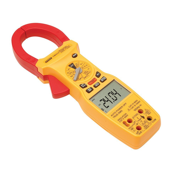
CMi210
CLAMP METER
4
4.1 Battery Replacement
4.2 Fuse Replacement
4.3 Test Lead Replacement
4.5 Cleaning
4.6 Repair & Service
4.7 Storage Conditions
5
Warranty
Measurment Categories
Specifi cations
Instruction
Manual
16/06/2014 11:40:19
CMi210 instructions rev1.indd 3
11
11
11
12
13
14
14
14
15
15
16
16
17
17
18
19
19
19
20
20
20
21
21
22
23
ALWAYS READ THESE INSTRUCTIONS BEFORE PROCEEDING
Thank you for buying one of our products. For safety and full
understanding of its benefi ts please read this manual before use.
Technical support is available from 01923 441717 and
support@martindale-electric.co.uk.
CONTENTS
1
Safety Information
1.1 Meaning of Symbols and Markings
1.2 Precautions
2
Introduction
2.1 Inspection
2.2 Description
2.3 Accessories
3
Operation
3.3 Description of Press Buttons
3.4 Description of LCD Symbols
3.5 Description of Terminals
3.6 Auto Power Off
3.7 Backlight
3.8 Auto/Manual Ranging
3.9 Display Hold
3.10 Max/Min
3.11 DC Current Zero
3.12 High Frequency Rejection
1 SAFETY INFORMATION:
REMEMBER: SAFETY IS NO ACCIDENT
These instructions contain both information and warnings that are necessary for
the safe operation and maintenance of this product. It is recommended that you
read the instructions carefully and ensure that the contents are fully understood.
Failure to understand and to comply with the warnings and instructions can result
in serious injury, damage or even death.
Particular attention should be paid to the Warnings, Precautions and Technical
Specifi cations.
Please keep these instructions for future reference. Updated instructions and
product information are available at: www.martindale-electric.co.uk
1.1 Meaning of Symbols and Markings
Caution - risk of danger & refer to instructions
Caution - risk of electric shock
Equipment protected by double or reinforced insulation (Class II)
Application around and removal from hazardous live conductors
is permitted.
Do not use in distribution systems with voltages higher than 680V.
>600V
Refers to the insulation resistance function.
CAT II
(Measurement Category II) is applicable to test and measuring
equipment connected directly to utilization points (socket outlets and
similar points) of the low-voltage MAINS installation.
CAT III
(Measurement Category III) is applicable to test and measuring
equipment connected to the distribution part of the building's low-
voltage MAINS installation.
CAT IV
(Measurement Category IV) is applicable to test and measuring
equipment connected at the source of the building's low-voltage
MAINS installation.
For further information on measurement categories refer to
page 23 or visit
1
www.martindale-electric.co.uk/measurement_categories.php
1
1
2
5
5
5
6
7
7
7
7
8
9
9
9
9
10
10
10
10
11
16/06/2014 11:40
Advertisement
Table of Contents

Related Manuals for MARTINDALE CMi210


Summary of Contents for MARTINDALE CMi210
-
Page 1: Table Of Contents
Specifi cations. 3.23 Capacitance Measurements Please keep these instructions for future reference. Updated instructions and 3.24 Frequency and Duty Cycle Measurements product information are available at: www.martindale-electric.co.uk 3.25 Temperature Measurements 1.1 Meaning of Symbols and Markings 3.26 Continuity Testing 3.27 Diode Testing Caution - risk of danger &... -
Page 2: 210 Instructions Rev1.Indd 4
2.2 Description temperature probe when voltages at the measurement surface The Martindale CMi210 is a combined clamp meter and insulation exceed 30V AC rms or 60V DC. tester with the following measurement functions:... - Page 3 2.3 Accessories 3. OPERATION The CMi210 comes with the following accessories: 3.1 General Carrying case If the magnitude of a parameter to be measured is uncertain, but Set of TL45 test leads known to be within the maximum safe limits of the electrical tester, Type K thermocouple manually set the range to maximum.
-
Page 4: Lock Function
Press again to return to HFR2. trigger to open the clamp jaws, position the jaws around the 210 instructions rev1.indd 20 16/06/2014 11:40:22 CMi210 instructions rev1.indd 21 16/06/2014 11:40 conductor to be measured, and release the trigger to close the jaws. 3.18 Inrush Current Measurements... -
Page 5: Ac Voltage Measurements
210 instructions rev1.indd 28 16/06/2014 11:40:23 CMi210 instructions rev1.indd 29 16/06/2014 11:40 Read the measured capacitance from the display. 3.26 Continuity Testing Connect the black test lead to the COM terminal and the red test 3.24 Frequency and Duty Cycle Measurements... -
Page 6: Insulation Resistance Measurements
4.3 Test Lead Replacement There are no user serviceable parts in this unit other than those that may be described in section 4. Return to Martindale Electric if faulty. If the test leads become damaged they should be replaced. Our service department will quote promptly to repair any fault that The replacement test leads must have the same (or better) overvoltage category rating as the TL45 leads supplied. - Page 7 5. WARRANTY AND LIMITATION OF LIABILITY This Martindale product is warranted to be free from defects in material and workmanship under normal use and service. The warranty period is 2 years and begins on the date of receipt by the end user. This warranty...
- Page 8 2.0% + 5 0.01M 3.5% + 5 Overload protection: 600V DC or AC rms Speci cation Speci cation 210 instructions rev1.indd 10 16/06/2014 11:40:20 CMi210 instructions rev1.indd 7 16/06/2014 11:40 CMi210 CMi210 Insulation Clamp Meter Insulation Clamp Meter Duty Cycle Insulation Resistance...
-
Page 9: General
5 x 1.5V AA batteries (installed), instructions 2.5G to 6G Speci cation 210 instructions rev1.indd 2 16/06/2014 11:40:20 CMi210 instructions rev1.indd 5 16/06/2014 11:40 Check out what else you can get from Martindale: CMi210 • • 17th Edition Testers Motor Maintenance Equipment •...
Need help?
Do you have a question about the CMi210 and is the answer not in the manual?
Questions and answers