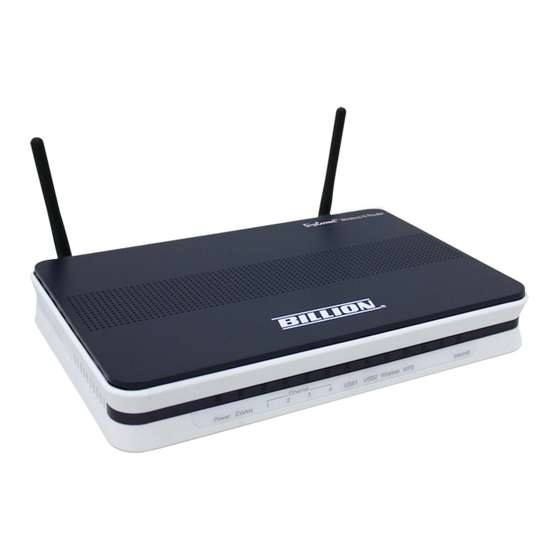
Billion BiPAC 6300NX User Manual
Fibre/4g lte/cable gigabit wireless-n
(vpn) broadband router
Hide thumbs
Also See for BiPAC 6300NX:
- Features & specifications (2 pages) ,
- Quick start manual (9 pages)

Related Manuals for Billion BiPAC 6300NX


Summary of Contents for Billion BiPAC 6300NX
-
Page 1: User Manual
BiPAC 6300NX(L) Fibre/4G LTE/Cable Gigabit Wireless-N (VPN) Broadband Router User Manual Version Released: 1.02b.rc5.dy2 Last Revised Date: May 30, 2013... -
Page 2: Table Of Contents
Table of Contents Chapter 1................................1 1.1 Introducing the BiPAC 6300NX(L) ........................ 1 1.2 Features of the BiPAC 6300NX(L)......................... 3 Network Protocols and Features........................3 Firewall ................................4 Quality of Service Control..........................4 IPTV Applications ............................4 Wireless LAN..............................4 USB Application Server ...........................4 Virtual Private Network (VPN) (BiPAC 6300NX only) ..................4 Management ..............................5 1.3 Hardware Specifications..........................5 Physical Interface............................5 1.4 Applications for the BiPAC 6300NX(L)......................6 Chapter 2................................7 2.1 Important note for using the BiPAC 6300NX(L) ...................7 2.2 Package Contents ............................8 2.3 The Front LEDs..............................9 2.4 The Rear Ports ............................10 The detail instruction in Reset Button......................11 2.6 Cabling................................11 Chapter 3................................12 3.1 Before Configuration..........................12 3.1.1 Configuring a PC in Windows 7 ......................13 3.1.2 Configuring a PC in Windows Vista......................16 ... - Page 3 5.1 Configuring 6300NX(L) with your Web Browser ..................28 5.2 Status................................30 5.2.1 Device Info ............................31 5.2.2 System Log............................33 5.2.3 Statistics...............................33 5.2.4 DHCP Table ............................37 5.2.5 ARP Table.............................37 5.2.6 IPSEC Status (6300NX only) .........................38 5.2.7 PPTP Status (6300NX only) ........................39 5.2.8 Disk Status ............................40 5.2.9 L2TP Status(6300NX only)........................40 5.3 Quick Start..............................41 5.4 Configuration..............................47 5.4.1 Interface Setup ............................48 5.4.1.1 Internet ............................48 5.4.1.2 LAN..............................57 5.4.1.3 Wireless............................60 5.4.1.4 Wireless MAC Address Filter......................72 5.4.2 Dual WAN ............................73 5.4.2.1 General Setting ..........................73 5.4.2.2 Outbound Load Balance (6300NX only)..................76 5.4.2.3 Protocol Binding (6300NX only)....................77 5.4.3 Advanced Setup...........................78 5.4.3.1 Firewall............................78 5.4.3.2 Routing............................79 5.4.3.3 NAT..............................81 5.4.3.4 Static DNS............................86 5.4.3.5 QoS..............................87 5.4.3.6 Interface Grouping (6300NXL only) ....................88 5.4.3.6 IPSEC Setting (6300NX only) ......................90 ...
- Page 4 5.4.5.2 Time Zone ...........................143 5.4.5.3 Firmware .............................144 5.4.5.4 System Restart ..........................146 5.4.5.5 Diagnostics Tool ..........................147 Chapter 6................................148 Problems starting up the router ......................148 Problems with the LAN Interface......................148 Recovery procedures for non‐working routers ..................149 APPENDIX ................................150 ...
-
Page 5: Introducing The Bipac 6300Nx(L)
3G/4G LTE network in the event that your fibre/cable line fails. The BiPAC 6300NX(L) will then automatically reconnect to the fibre/cable connection when it is restored, reducing connection costs. These features are perfect for office situations where a constant and uninterrupted connection is in need. - Page 6 IPSec VPN performance significantly. 3G/4G LTE Management Center The BiPAC 6300NX(L) Cellular Management Center visually displays its current 3G/4G LTE signal status It also calculates the total amount of hours or data traffic used per month, allowing you to manage your 3G/4G LTE monthly subscriptions.
-
Page 7: Chapter 1
• IEEE 802.11 b/g/n compliant Wireless Access Point with Wi-Fi Protected Setup (WPS) • Wi-Fi Protected Access (WPA-PSK/ WPA2-PSK) and Wired Equivalent Privacy (WEP) • Secured IPSec VPN with powerful DES/ 3DES/ AES (BiPAC 6300NX only) • PPTP VPN with Pap/ Chap/ MPPE authentication (BiPAC 6300NX only) •... -
Page 8: Firewall
USB Application Server • 3G/4G LTE dongle support • Storage/NAS: Samba server, FTP Server Virtual Private Network (VPN) (BiPAC 6300NX only) • 8 IPSec VPN Tunnels • 8 PPTP VPN Tunnels (Dial-in:4, Dial-out:4) • 8 L2TP VPN Tunnels (Dial-in:4, Dial-out:4) -
Page 9: Management
Management • Easy Sign-on (EZSO) • Quick Installation wizard • Web-based GUI for remote and local management (IPv4/IPv6) • Firmware upgrades and configuration data upload and download via web-based GUI • Supports DHCP server / client / relay • Supports SNMP v1,v2, v3, MIB-I and MIB-II TR-069* supports remote management •... -
Page 10: Hardware Specifications
1.3 Hardware Specifications Physical Interface • WLAN: 2 detachable antennas • USB: 2 USB 2.0 type A port for storage service and 3G/4G LTE dongle • Ethernet: 4-port 10 / 100 / 1000Mbps auto-crossover (MDI / MDI-X) Switch • EWAN: RJ-45 Gigabit Ethernet port for connecting to ADSL/Cable/VDSL/Fibre modem for Broadband connectivity. -
Page 11: Applications For The Bipac 6300Nx(L)
1.4 Applications for the BiPAC 6300NX(L) BiPAC 6300NX(L) is a all-in-one router, supporting alternative ways (3G, EWAN) to connect to the Internet. Then users can choose one of the ways to connect to the Internet or ISP. Broadband router mode... - Page 12 3G router mode BiPAC 6300NX(L) embeds two USB ports supporting two 3G/4G LTE connections at the same time, which is especially useful if one 3G/4G LTE card is running out of cost (the USB port can also support the NAS storage...
-
Page 13: Chapter 2
Do not use the same power source for the BiPAC 6300NX(L) as other equipment. Do not open or repair the case yourself. If the BiPAC 6300NX(L) is too hot, turn off the power immediately and have it repaired at a qualified service center. Warning ... -
Page 14: Package Contents
2.2 Package Contents BiPAC 6300NX(L) Fibre/4G LTE/Cable Gigabit Wireless-N (VPN) Broadband Router CD containing user manual Ethernet (CAT-5 LAN) cable Power adapter Quick Start Guide Two 2dBi detachable Antennas... -
Page 15: The Front Leds
2.3 The Front LEDs Status Meaning Router powered on Power Green System ready Green Transmission speed hitting 1000Mbps EWAN Orange Transmission speed hitting 10/100Mbps Blinking Data being transmitted/received Green Transmission speed hitting 1000Mbps Ethernet Port Orange Transmission speed hitting 10/100Mbps Blinking Data being transmitted/received Green... -
Page 16: The Rear Ports
2.4 The Rear Ports Port Meaning Power ON/OFF switch Power Switch Connect the supplied power adapter to this jack. Power After the device is powered on, press it 6 seconds or above: to restore to factory default settings (this is used when you can not login to the router, e.g. forgot the RESET password) By controlling the pressing time, users can achieve two different effects:... -
Page 17: The Detail Instruction In Reset Button
Make sure that all other devices (e.g. telephones, fax machines, analogue modems) connected to the same telephone line as your Billion router have a line filter connected between them and the wall socket (unless you are using a Central Splitter or Central Filter installed by a qualified and licensed electrician), and that all line filters are correctly installed in a right way. -
Page 18: Chapter 3
The TCP/IP protocol stack and Ethernet network adapter must be installed. If not, please refer to your Windows-related or other operating system manuals. Any TCP/IP capable workstation can be used to communicate with or through the BiPAC 6300NX(L). To configure other types of workstations, please consult the manufacturer’s documentation. -
Page 19: Configuring A Pc In Windows 7
3.1.1 Configuring a PC in Windows 7 Go to Start. Click on Control Panel. Then click on Network and Internet. When Network Sharing Center window pops up, select and click on Change adapter settings on the left window panel. Select Local Area Connection, and right click the... - Page 20 IPv4: 1) Select Internet Protocol Version 4 (TCP/IPv4) then click Properties 2) In TCP/IPv4 properties window, select the Obtain an IP automatically and address Obtain DNS Server address automatically radio buttons. Then click OK to exit the setting. 3) Click OK again in the Local Area Connection Properties window to apply the new...
- Page 21 IPv6: Select Internet Protocol Version 6 (TCP/IPv6) then click Properties In the TCP/IPv6 properties window, select the Obtain an IPv6 address automatically Obtain Server address automatically radio buttons. Then click OK to exit the setting. Click OK again in the Local Area Connection Properties window to apply the new configuration.
-
Page 22: Configuring A Pc In Windows Vista
3.1.2 Configuring a PC in Windows Vista 1. Go to Start. Click on Network. 1. Then click on Network and Sharing Center at the top bar. 2. When Network Sharing Center window pops up, select and click on Manage network connections on the left window pane. - Page 23 IPv4: 4. Select Internet Protocol Version 4 (TCP/IPv4) then click Properties. 5. In the TCP/IPv4 properties window, select the Obtain an IP address automatically Obtain DNS Server address automatically radio buttons. Then click OK to exit the setting. 6. Click OK again in the Local Area Connection Properties window apply...
-
Page 24: Configuring A Pc In Windows Xp
3.1.3 Configuring a PC in Windows XP IPv4: 7. Go to Start / Control Panel (in Classic View). In the Control Panel, double-click on Network Connections 8. Double-click Local Area Connection. 9. In the Local Area Connection Status window, click Properties. 10. - Page 25 IPv6: IPv6 is supported by Windows XP, but you should install it first. Act as shown below: 1. On the desktop, Click Start > Run, type cmd, then press Enter key in the keyboard, the following screen appears. 2. Key in command ipv6 install Configuration is OK now, you can test whether it works ok.
-
Page 26: Configuring A Pc In Windows 2000
3.1.3 Configuring a PC in Windows 2000 1. Go to Start / Settings / Control Panel. In the Control Panel, double-click on Network and Dial-up Connections. 2. Double-click Local Area Connection. 3. In the Local Area Connection Status window click Properties. 4. -
Page 27: Configuring A Pc In Windows 98/Me
3.1.4 Configuring a PC in Windows 98/Me 1. Go to Start / Settings / Control Panel. In the Control Panel, double-click on Network and choose the Configuration tab. 2. Select TCP/IP ->NE2000 Compatible, or the name of your Network Interface Card (NIC) in your PC. -
Page 28: Configuring A Pc In Windows Nt4.0
3.1.5 Configuring a PC in Windows NT4.0 1. Go to Start / Settings / Control Panel. In the Control Panel, double-click on Network and choose the Protocols tab. Select click TCP/IP Protocol Properties. 3. Select the Obtain an IP address from a DHCP server radio button and click OK. -
Page 29: Factory Default Settings
3.2 Factory Default Settings Before configuring your router, you need to know the following default settings. Web Interface: Username: admin Password: admin LAN Device IP Settings: IP Address: 192.168.1.254 Subnet Mask: 255.255.255.0 ISP setting in WAN site: PPPoE DHCP server: DHCP server is enabled. -
Page 30: Lan And Wan Port Addresses
3.3 LAN and WAN Port Addresses The parameters of LAN and WAN ports are pre-set in the factory. The default values are shown below. IPv4: LAN Port WAN Port 192.168.1.254 The PPPoE function is IP address enabled to automatically 255.255.255.0 Subnet Mask get the WAN port configuration from the... -
Page 31: Chapter 4
Chapter 4 Easy Sign-On (EZSO) 4.1 Easy Sign-On (EZSO) This EZSO feature makes it easier for you to configure your router so that you can connect to the internet in a couple of seconds without having to logon to the router's GUI for any detail configuration. This configuration method is usually auto initiated if user is to connect to the internet via 6300NX(L). - Page 32 Step 4: EZSO finished. (The default configuration is base on IPv4/IPv6) Step 1: Choose the 3G_1 (BiPAC 6300NX(L) supports two 3G connections, and choose one to configure.) Press Continue to move on. Step 2: Type the 3G account information. Press NEXT to continue.
- Page 33 Step 4: EZSO finished.
-
Page 34: Chapter 5
Open your web browser, enter the IP address of your router, which by default is 192.168.1.254, and click “OK”, a user name and password window prompt will appear. The default username and password are “admin” and “admin”. Congratulation! You are now successfully logged on to the BiPAC 6300NX(L)! - Page 35 Status (6300NX only), Disk Status, L2TP Status (6300NX only)) Quick Start (Wizard Setup) Configuration (Interface Setup, Dual WAN, Advanced Setup, Access Management, Maintenance) Language Please see the relevant sections of this manual for detailed instructions on how to configure your Billion router.
-
Page 36: Status
5.2 Status In this section,you can check the router working status, including Device Info, System Log, Statistics, DHCP Table, ARP Table, IPSEC Status (6300NX only), PPTP Status (6300NX only), Disk Status, and L2TP Status (6300NX only). -
Page 37: Device Info
5.2.1 Device Info... - Page 38 Device Information Model Name: Show model name of the router Firmware Version: This is the Firmware version MAC Address: This is the MAC Address IPv4: IP Address: LAN port IPv4 address. Sub Net Mask: LAN port IP subnet mask. DHCP Server: LAN port DHCP role - Enabled, Relay or disabled ...
-
Page 39: System Log
5.2.2 System Log In system log, users can check the operations to the router and track the glitches to the router when occurred. 5.2.3 Statistics Ethernet Interface: This field displays the type of port Transmit Frames: This field displays the number of frames transmitted until the latest second. Transmit Multicast Frames: This field displays the number of multicast frames transmitted until the latest second. - Page 40 Receive Total Bytes: This field displays the number of bytes received until the latest second. Receive CRC Errors: This field displays the number of error packets on this port. Receive Under-size Frames: This field displays the number of under-size frames received until the latest second.
- Page 41 EWAN Transmit Frames: This field displays the total number of frames transmitted until the latest second. Transmit Multicast Frames: This field displays the total number of multicast frames transmitted till the latest second. Transmit Total Bytes: This field displays the total number of bytes transmitted until the latest second. Transmit Collision: This is the number of collisions on this port.
- Page 42 3G_1 Take 3G_1 as an example to describe the 3G/4G LTE connection transmission information. Transmit Frames of Current Connection: This field displays the total number of 3G/4G LTE frames transmitted until the latest second for the current connection. Transmit Bytes of Current Connection: This field shows the total bytes transmitted till the latest second for the current connection for the current connection.
-
Page 43: Dhcp Table
5.2.4 DHCP Table DHCP table displays the devices connected to the router with clare information. #: The index identifying the connected devices. HostName: Show the hostname of the PC. IP: The IP allocated to the device. MAC Address: The MAC of the connected device. Expire Time: The total remaining interval since the IP assignment to the PC. -
Page 44: Ipsec Status (6300Nx Only)
5.2.6 IPSEC Status (6300NX only) #: The IPSec entry index number. Connection Name: User-defined IPSEC VPN connection name. Remote Gateway: The IP of the remote gateway. Local Address: The IP and netmask of local access range. Remote address: The IP and netmask of remote access range. Connected: Show the connecting status. -
Page 45: Pptp Status (6300Nx Only)
5.2.7 PPTP Status (6300NX only) PPTP Client User: Four users(sessions) for client sessions. Here shows the using user. Connection Name: Show user-defined PPTP VPN connection name. Active: Show if the tunnel is active for connection. Connection Type: Remote Access or LAN to LAN. Server IP: Show the IP of VPN Server. -
Page 46: Disk Status
5.2.8 Disk Status Partition: Display the NAS partition. Disk Space(KB): Display the total storage space of the NAS in KB unit. Free Space(KB): Display the available space in KB unit. 5.2.9 L2TP Status(6300NX only) Name: Display the user-defined L2TP connection name. Type: The VPN mode: dialin or dialout. -
Page 47: Quick Start
5.3 Quick Start For detailed instructions on configuring WAN settings, see the Interface Setup section of this manual. The Quick Start Wizard is a useful and easy utility to help setup the device to quickly connect to your ISP (Internet Service Provider) with only a few steps required. It will guide you step by step to configure the password, time zone, and WAN settings of your device. - Page 48 Step3: Set your wireless connection. Click NEXT to continue.
- Page 49 Step4: Set your Internet connection WAN Transfer Modes: EWAN or 3G. EWAN 1) .Select EWAN. Refer to your ISP to choose the appropriate connection protocol. Click NEXT to continue. 1) Enter the PPPoE account information provided to you by your ISP. Click NEXT to continue. 2).The Setup Wizard has completed.
- Page 50 If configuration is completed, users can change to Status > Device Info for information.
- Page 51 1) Select 3G_1 (for example). 2). Type relevant 3G parameters from your ISP. 3). Click Next to save changes. 4). Quick Start completed!.
- Page 52 Switch to Status > Device Info to view the status.
-
Page 53: Configuration
5.4 Configuration Click this item to access the following sub-items that configure the router: Interface Setup, Dual WAN, Advanced Setup, Access Management, and Maintenance. First, let us take a look at the Interface Setup. There are four items contained in this section, namely, Internet, LAN, Wireless and Wireless MAC Filter. -
Page 54: Interface Setup
5.4.1 Interface Setup 5.4.1.1 Internet EWAN BiPAC 6300NXL... - Page 55 BiPAC 6300NX...
- Page 56 Multi Service (6300NXL only) Service Num: The index to mark the EWAN interface of different ISP type, ranging from 0-7. Service Summary: The diagram for view of service information. Status: Select whether to enable the service. IPv4/IPv6 IP version: choose IPv4, IPv4/IPv6, IPv6 based on users’ environment. Here we take IPv4/IPv6 for example, when you just choose IPv4 or IPv6, you can just get information from the following listed parameters.
- Page 57 working in the internet. Connection Setting Connection: Always On: Click on Always On to establish a PPPoE session during start up and to automatically re-establish the PPPoE session when disconnected by the ISP. Connect Manually: Select Connect Manually when you don't want the connection up all the time. TCP MSS Option: Enter the TCP Maximum Segment Size (MSS).
- Page 58 When router’s Internet configuration is finished successfully, you can go to status to get the connection information. BiPAC 6300NXL...
- Page 59 BiPAC 6300NX...
- Page 60 The BiPAC 6300NX(L) supports two 3G connections, featuring 3G_1 and 3G_2. Status: Choose Activated to enable the 3G connection. Usage Allowance: Enable when you want to control 3G usage. Click this link to enter 3G Usage Allowance configure. Mode: There are 5 options of phone service standards: GSM_ONLY, UTMS_ONLY, GPRS_FIRST, UMTS_FIRST, and AUTOMATIC.
- Page 61 3G Usage Allowance Click Usage Allowance to go to the Usage Allowance configuration page. In order to query online time or volume used, you can set the following options. Mode: Two methods are provided, that is, Volume-based and Time-based. Volume-based: If choosing Volume-based, you can view the volume you have used. Only Download: Only make statistics of Download Traffic.
- Page 62 Time-based: If choosing Time-based, you can view the online hours you have used. You can also assign the billing period. Over usage allowance action: If the online time or traffic you have used exceeds the usage allowance you set. The system will do the followings operations.
-
Page 63: Lan
5.4.1.2 LAN A Local Area Network (LAN) is a shared communication system to which many computers are attached and is limited to the immediate area, usually the same building or floor of a building. IPv6 The IPv6 address composes of two parts, thus, the prefix and the interface ID. There are two ways to dynamically configure IPv6 address on hosts. - Page 64 If set to Disabled, the DHCP server will be disabled. If set to Relay, the BiPAC 6300NX(L) acts as a surrogate DHCP server and relays DHCP requests and responses between the remote server and the clients. Enter the IP address of the actual, remote DHCP server in the Remote DHCP Server field in this case.
- Page 65 IP Address: Enter the specific IP. For example: 192.168.1.110. MAC Address: Enter the responding MAC. For example: 00:0A:F7:45:6D:ED When added, you can see the ones listed as showed below: IPv6 parameters Interface Address / Prefix Length: enter the static LAN IPv6 address, we suggest leave the field empty because when setted wrong, it will result in LAN devices not being able to access other IPv6 device through internet.
-
Page 66: Wireless
5.4.1.3 Wireless This section introduces the wireless LAN and some basic configurations. Wireless LANs can be as complex as a number of computers with wireless LAN cards communicating through access points which bridge network traffic to the wired LAN. - Page 67 Access Point Settings Access Point: Default setting is set to Activated. If you want to close the wireless interface, select Deactivated. Wireless Mode: The default setting is 802.11b+g+n (Mixed mode). If you do not know or have both 11g and 11b devices in your network, then keep the default in mixed mode.
- Page 68 WPS Settings WPS (Wi-Fi Protected Setup) feature is a standard protocol created by Wi-Fi Alliance. This feature greatly simplifies the steps needed to create a Wi-Fi networks for a residential or an office setting. WPS supports 2 types of configuration methods which are commonly known among consumers: &...
- Page 69 3. Launch the wireless client’s WPS utility (eg. Ralink Utility). Set the Config Mode as Enrollee, press the WPS button on the top bar, select the AP (eg. Billion_AP) from the WPS AP List column. Then press the PIN button located on the middle left of the page to run the scan.
- Page 70 4. The client’s SSID and security setting will now be configured to match the SSID and security setting of the registrar (router).
- Page 71 PIN Method: Configure AP as Enrollee 1. Jot down the WPS PIN (eg. 03454435).Press Start WPS.
- Page 72 2. Launch the wireless client’s WPS utility (eg. Ralink Utility). Set the Config Mode as Registrar. Enter the PIN number in the PIN Code column then choose the correct AP (eg. Billion_AP) from the WPS AP List before pressing the PIN button to run the scan.
- Page 73 3. The router’s (AP’s) SSID and security setting will now be configured to match the SSID and security setting of the registrar (client). 4. Now to make sure that the setup is correctly done, cross check to see if the SSID and the security setting of the registrar setting match with the parameters found on both Wireless Configuration and Wireless Security Configuration page.
- Page 74 PBC Method: 1. Press the PBC radio button, Then Start WPS. 2. Launch the wireless client’s WPS Utility (eg. Ralink Utility). Set the Config Mode as Enrollee. Then press the WPS button and choose the correct AP (eg. Billion_AP) from the WPS AP List section before pressing the PBC button to run the scan.
- Page 75 3. When the PBC button is pushed, a wireless communication will be established between your router and the PC. The client’s SSID and security setting will now be configured to match the SSID and security setting of the router.
- Page 76 Security Settings Security Type: You can disable or enable wireless security for protecting wireless network. The default type of wireless security is OPEN and to allow all wireless stations to communicate with the access points without any data encryption. To prevent unauthorized wireless stations from accessing data transmitted over the network, the router offers secure data encryption, known as WEP and WPA.
- Page 77 WPA-PSK & WPA2-PSK WPA Algorithms: TKIP (Temporal Key Integrity Protocol) or AES (Advanced Encryption System) utilizes a stronger encryption method and incorporates Message Integrity Code (MIC) to provide protection against hackers. Pre-Shared key: The key for network authentication. The input format should be 8-63 ASKII characters or 64 hexadecimal characters Key Renewal Interval: The time interval for changing the security key automatically between wireless client and AP.
-
Page 78: Wireless Mac Address Filter
5.4.1.4 Wireless MAC Address Filter The MAC filter screen allows you to configure the router to give exclusive access to up to 8 devices (Allow Association) or exclude up to 8 devices from accessing the router (Deny Association). Every Ethernet device has a unique MAC (Media Access Control) address. -
Page 79: Dual Wan
WAN 2 (backup WAN), and when WAN1 fails, it will switch to WAN2, and when WAN1 restores, it will switch to WAN1 again. Load balance (only for BiPAC 6300NX) provides optimal bandwidth sharing for multiple PCs on your network, or allows maximum reliability with network redundancy. Load balance supported by BiPAC 6300NX balance... - Page 80 Note: 1) The time set is for each probe cycle, but the decision to change to the backup port is determined by Probe Cycle multiplied by connection Decision amount (e.g. From the image above it will be 30 seconds multiplied by 3 consecutive fails, the router will determine failover to WAN2 (backup port)).
- Page 81 Probe WAN 1/2: Choose the probe policy, to probe gateway or host (users decide themselves) Gateway: It will send ping packets to gateway of Wan1 interface and wait for response from it in every “Probe Cycle” to check the connectivity of the gateway of WAN1 interface. Host: It will send ping packets to specific host and wait for response in every “Probe Cycle”.
-
Page 82: Outbound Load Balance (6300Nx Only)
5.4.2.2 Outbound Load Balance (6300NX only) The connections are distributed over WAN1 and WAN2 so that it can utilize bandwidth of both WAN ports. With Outbound load balance, traffic may be routed to a faster link when one of the WAN is slower or congested so that user gains better throughput and less delay. -
Page 83: Protocol Binding (6300Nx Only)
5.4.2.3 Protocol Binding (6300NX only) Protocol Binding lets you direct specific traffic to go out from a specific WAN port. Policies determine how specific types of internet traffic are routed, for example, traffic from a particular IP(es) granted access to only one WAN port rather than using both of the WAN ports as with load balancing. -
Page 84: Advanced Setup
5.4.3 Advanced Setup 5.4.3.1 Firewall Your router includes a firewall for helping to prevent attacks from hackers. In addition to this, when using NAT (Network Address Translation) the router acts as a “natural” Internet firewall, since all PCs on your LAN use private IP addresses that cannot be directly accessed from the Internet. -
Page 85: Routing
5.4.3.2 Routing This is static route feature. You are equipped with the capability to control the routing of all the traffic across your network. With each routing rule created, user can specifically assign the destination where the traffic will be routed to. - Page 86 ADD Route Destination IP Address: This is the destination subnet IP address. Destination Subnet Mask: The subnet mask of destination network. Gateway IP Address/Interface:This is the gateway IP address or existing interface to which packets are to be forwarded. Metric:It represents the cost of transmission for routing purposes. The number need not be precise, but it must be between 1 and 15.
-
Page 87: Nat
5.4.3.3 NAT The NAT (Network Address Translation) feature transforms a private IP into a public IP, allowing multiple users to access the internet through a single IP account, sharing the single IP address. NAT break the originally envisioned model of IP end-to-end connectivity across the internet so NAT can cause problems where IPSec/ PPTP encryption is applied or some application layer protocols such as SIP phones are located behind a NAT. - Page 88 The DMZ Host is a local computer exposed to the Internet. When setting a particular internal IP address as the DMZ Host, all incoming packets will be checked by the Firewall and NAT algorithms then passed to the DMZ host, when a packet received does not use a port number used by any other Virtual Server entries. DMZ for: Indicate the related WAN interface which allows outside network to connect in and communicate.
- Page 89 Virtual Server In TCP/IP networks a port is a 16-bit number used to identify which application program (usually a server) incoming connections should be delivered to. Some ports have numbers that are pre-assigned to them by the IANA (the Internet Assigned Numbers Authority), and these are referred to as “well-known ports”. Servers follow the well-known port assignments so clients can locate them.
- Page 90 Examples of well-known and registered port numbers are shown below. For further information, please see IANA’s website at http://www.iana.org/assignments/port-numbers Well-known and Registered Ports Port Number Protocol Description FTP Control TCP & UDP SSH Remote Login Protocol Telnet SMTP (Simple Mail Transfer Protocol) TCP &...
- Page 91 Some tips for using DMZ and Virtual Server: Using port forwarding does have security implications, as outside users will be able to connect to PCs on your network. For this reason you are advised to use specific Virtual Server entries just for the ports your application requires, instead of using DMZ.
-
Page 92: Static Dns
5.4.3.4 Static DNS The Domain Name System (DNS) is a hierarchical naming system built on a distributed database for computers, services, or any resource connected to the Internet or a private network associates various information with domain names assigned to each of the participating entities. Most importantly, it translates domain names meaningful to humans into the numerical identifiers associated with networking equipment for the purpose of locating and addressing these devices worldwide. -
Page 93: Qos
5.4.3.5 QoS QoS helps you control the upload traffic of each application from LAN(Ethernet and/or Wireless) to WAN (Internet). It facilitates you the features to control the quality of throughput for each application. This is useful when there on certain types of data you want giver higher priority to, such as voice data packets given higher priority than web data packets. -
Page 94: Interface Grouping (6300Nxl Only)
5.4.3.6 Interface Grouping (6300NXL only) Interface grouping is a function to group interfaces, known as VLAN. A Virtual LAN, commonly known as a VLAN, is a group of hosts with the common set of requirements that communicate as if they were attached to the same broadcast domain, regardless of the physical location. - Page 95 You are going to group the ports and services into two working group, as shown below. Group Index Group Port ewan0_0,e3,e4,w2,w3,w4 ewan0_1,e1,e2,w1 Click PortBinding Summary to show the configuration results.
-
Page 96: Ipsec Setting (6300Nx Only)
5.4.3.6 IPSEC Setting (6300NX only) A Virtual Private Network (VPN) is a private network that interconnects remote (and often geographically separate) networks through primarily public communication infrastructures such as the Internet. VPNs provide security through tunneling protocols and security procedures such as encryption. For example, a VPN could be used to securely connect the branch offices of an organization to a head office network through the public Internet. - Page 97 Click Add New Connection to create IPSec connections. VPN Connection Setting Active: Select Yes to activate the tunnel. Connection Name: A given name for the connection (e.g. “connection to office”). Interface: Select the set used interface for the IPSec connection, when you select EWAN interface, the IPSec tunnel would transmit data via this interface to connect to the remote peer.
- Page 98 (IPv4 and IPv6 supported). Encryption Algorithm: Select the encryption algorithm from the drop-down menu. There are several options: DES and AES (128, 192 and 256). 3DES and AES are more powerful but increase latency. DES: Stands for Data Encryption Standard, it uses 56 bits as an encryption method. ...
- Page 99 required. Default setting is 0.0.0.0 which disables the function Interval: This sets the time interval between Pings to the IP function to monitor the connection status. Default interval setting is 10 seconds. Time interval can be set from 0 to 3600 second, 0 second disables the function. Ping to the IP Interval (sec) Ping to the IP Action...
- Page 100 Examples: 1. LAN-to-LAN connection Two BiPAC 6300NXs want to setup a secure IPSec VPN tunnel The IPSec Settings shall be consistent between the two routers. Note:...
- Page 101 Head Office Side: Setup details: Item Function Description Connection Name H-to-B Give a name for IPSec connection Local Network Subnet Select Subnet IP Address 192.168.1.0 Head Office network Netmask 255.255.255.0 Secure Gateway IP address of the Branch office Address(Hostanme 69.121.1.30 router (on WAN side) Remote Network Subnet...
- Page 102 Branch Office Side: Setup details: the same operation as done in Head Office side Item Function Description Connection Name B-to-H Give a name for IPSec connection Local Network Subnet Select Subnet IP Address 192.168.0.0 Branch Office network Netmask 255.255.255.0 Remote Secure Gateway IP address of the Head office router 69.121.1.3...
- Page 103 2. Host to LAN Router servers as VPN server, and host should install the IPSec client to connect to head office through IPSec VPN. Item Function Description Host-to-Headoff Connection Name Give a name for IPSec connection Local Network Subnet Select Subnet IP Address 192.168.1.0 Head Office network...
-
Page 105: Pptp (6300Nx Only)
5.4.3.7 PPTP (6300NX only) The Point-to-Point Tunneling Protocol (PPTP) is a Layer2 tunneling protocol for implementing virtual private networks through IP network. PPTP uses an enhanced GRE (Generic Routing Encapsulation) mechanism to provide a flow- and congestion-controlled encapsulated datagram service for carrying PPP packets. In the Microsoft implementation, the tunneled PPP traffic can be authenticated with PAP, CHAP, and Microsoft CHAP V1/V2 . - Page 106 and the IP should be in the same subnet as local LAN, but not occupied. Peer Network IP: Please input the subnet IP for remote network. Peer Netmask: Please input the Netmask for remote network.
-
Page 107: Pptp Client (6300Nx Only)
5.4.3.8 PPTP Client (6300NX only) PPTP client can help you dial-in the PPTP server to establish PPTP tunnel over Internet. A total of 4 sessions can be created for PPTP client. User select: 4 sessions for client connection by default, user1 stands for the first session, and so does user2, etc. - Page 108 Example: PPTP Remote Access with Windows7 (Note: inside test with 172.16.1.233, just an example for illustration) Server Side: 1. Please move to Configuration > PPTP Server, Enable the PPTP Server and add an account as “test”. The exact setting can be found in the screenshot shown below.
- Page 109 Client Side: 1. In Windows7 click Start > Control Panel> Network and Sharing Center, Click Set up a new connection or network.
- Page 110 2. Click Connect to a workplace, and press Next. 3. Select Use my Internet connection (VPN) and press Next.
- Page 111 4. Input Internet address and Destination name for this connection and press Next.
- Page 112 5. Input the account (user name and password) and press Create.
- Page 113 6. Connect to the server.
- Page 114 7. Successfully connected. PS: You can also go to Network Connections shown below to check the detail of the connection. Right click “test” icon, and select “Properties” to change the security parameters (if the connection fails, users can go here to change the settings)
- Page 116 Example: Configuring a LAN-to-LAN PPTP VPN Connection The branch office establishes a PPTP VPN tunnel with head office to connect two private networks over the Internet. The routers are installed in the head office and branch offices accordingly. Both office LAN networks must be in different subnets with the LAN-LAN application. Note: Server side: Head Office Set an account of “test”...
- Page 117 Client Side: Branch Office The client user can set up a session connecting to the PPTP server.
-
Page 118: L2Tp (6300Nx Only)
5.4.3.9 L2TP (6300NX only) L2TP, Layer 2 Tunneling Protocol is a tunneling protocol used to support virtual private networks (VPNs). It does not provide any encryption or confidentiality by itself; it relies on an encryption protocol that it passes within the tunnel to provide. - Page 119 Dial In Active: To enable or disable the tunnel. Username: Please input the username for this account. Password: Please input the password for this account. Private IP Address Assigned to Dialin user: The private IP to be assigned to dialin user by L2TP server. The IP should be in the same subnet as local LAN, and should not be occupied.
- Page 120 Dial Out Active: To enable or disable the tunnel. Username: Enter the username provided by your VPN Server. Password: Enter the password provided by your VPN Server. Server IP Address: Enter the IP address of your VPN Server. Auth. Type: Default is Auto(CHAP, Challenge Handshake Authentication Protocol) if you want the router to determine the authentication type to use, or else manually specify PAP (Password Authentication Protocol) if you know which type the server is using (when acting as a client), or else the authentication type you want clients connecting to you to use (when acting as a server).
- Page 121 Examples: 1. Configuring a L2TP VPN - Remote Access Dial-in Connection A remote worker establishes a L2TP VPN connection with the head office using Microsoft's VPN Adapter (included with Windows XP/2000/ME, etc.). The router is installed in the head office, connected to a couple of PCs and Servers.
- Page 122 Configuring L2TP VPN in the Office The input IP address 192.168.1.200 will be assigned to the remote worker. Please make sure this IP is not used in the Office LAN. Function Description Name VPN_Server Give a name of L2TP Connection Select Remote Access from the Connection Type Connection Type Remote Access...
- Page 123 2. Configuring a Remote Access L2TP VPN Dial-out Connection A company’s office establishes a L2TP VPN connection with a file server located at a separate location. The router is installed in the office, connected to a couple of PCs and Servers.
- Page 124 Configuring L2TP VPN in the Office Function Description Name VPN_Client Give a name of L2TP Connection Select Remote Access from the Connection Type Connection Type Remote Access drop-down menu Type Dial out Select Dial out from the Type drop down menu IP Address (or 69.121.1.33 A Dialed Server IP...
- Page 125 Example: Configuring L2TP LAN-to-LAN VPN Connection The branch office establishes a L2TP VPN tunnel with head office to connect two private networks over the Internet. The routers are installed in the head office and branch office accordingly. Both office LAN networks must be in different subnets with the LAN-LAN application. Note:...
- Page 126 Configuring L2TP VPN in the Head Office The IP address 192.168.1.200 will be assigned to the router located in the branch office. Please make sure this IP is not used in the head office LAN. Function Description Name HeadOffice Give a name of L2TP Connection Connection Type LAN to LAN Select LAN to LAN from the Connection Type...
- Page 127 Configuring L2TP VPN in the Branch Office The IP address 69.1.121.33 is the Public IP address of the router located in head office. If you registered the DDNS (please refer to the DDNS section of this manual), you can also use the domain name instead of the IP address to reach the router.
-
Page 128: Port Isolation
5.4.3.10 Port Isolation Port isolation is a mechanism to allow or block devices in one port (indicates the P1-P4 and WP1 – WP4) to access other devices in other ports. By default, all ports (LAN port and WLAN port) are sharing one group, and devices in all these ports can have access to each other. -
Page 129: Time Schedule
5.4.3.11 Time Schedule The Time Schedule supports up to 16 timeslots which helps you to manage your Internet connection. In each time profile, you may schedule specific day(s) i.e. Monday through Sunday to restrict or allowing the usage of the Internet by users or applications. This Time Schedule correlates closely with router’s time, since router does not have a real time clock on board;... -
Page 130: Access Management
Simple Network Management Protocol (SNMP) is a protocol used for exchanging management information between network devices. SNMP is a member of the TCP/IP protocol suite. BiPAC 6300NX(L) serves as a SNMP agent which allows a manager station to manage and monitor the router through the network. -
Page 131: Upnp
Auto-configured: Select this check box to allow UPnP-enabled applications to automatically configure the BiPAC 6300NX(L) so that they can communicate through the BiPAC 6300NX(L), for example by using NAT traversal, UPnP applications automatically reserve a NAT forwarding port in order to communicate with another UPnP enabled device;... -
Page 132: Ddns
Dynamic DNS: Select this check box to activate Dynamic DNS. Service Provider: Select from drop-down menu for the appropriate service provider, for example: www.dyndns.org. My Host Name: Type the domain name assigned to your BiPAC 6300NX(L) by your Dynamic DNS provider. Username: Type your user name. - Page 133 User can register different DDNS to different interfaces. Examples: first users have to go to the Dynamic DNS registration service provider to register an account. Note User test register two Dynamic Domain Names in DDNS provider http://www.dyndns.org/ 1. EWAN with DDNS: www.hometest.com using username/password test/test 2.
-
Page 134: Access Control
Active: Select to activate the rule. Secure IP Address: The default 0.0.0.0 allows any client to use this service to manage the BiPAC 6300NX(L). Type an IP address range to restrict access to the client(s) without a matching IP address. - Page 135 Examples: 1). Set a rule to allow only clients from LAN to have access to all embedded applications (Web, FTP, etc). Under this situation, clients from WAN can not access the router even from Ping. 2). Generally, we always open Ping to WAN side, and user can now add another ACL rule granting Ping service to WAN side clients.
-
Page 136: Filter
5.4.4.5 Filter You can filter the packages by MAC address, IP address, Protocol, Port number and Application or URL. IP & MAC Filter Packet Filter Filter Type: There are three types “IP & MAC Filter”, “Application Filter”, and “URL Filter” that user can select for this filter rule. - Page 137 Source Port Number: The source port number of packets to be monitored. 0 means “Don’t care”. Destination IP Address: The destination IP address of packets to be monitored. 0.0.0.0 means “Don’t care”. Destination Subnet Mask: Enter the subnet mask of the destination network. Destination Port Number: This is the Port that defines the application.
- Page 138 Application Filter Application Filter: Select this option to Activated/Deactivated the Application filter. ICQ: Select this option to Allow/Deny ICQ. MSN: Select this option to Allow/Deny MSN. YMSG: Select this option to Allow/Deny Yahoo messenger. Real Audio/Video(RTSP): Select this option to Allow/Deny Real Audio/Video (RTSP).
- Page 139 URL Filter URL Filter: Select Activated to enable URL Filter. URL Filter Rule Index: This is item number. Individual Active: To give control to the specific URL access individually, for example, you want to prohibit access to www.yahoo.com, please first press Activated in “URL Filter” field, and also Yes in “Individual Active” field;...
-
Page 140: Cwmp (Tr-069)
5.4.4.6 CWMP (TR-069) CWMP, short for CPE WAN Management Protocol, also called TR069 is a Broadband Forum technical specification entitled CPE WAN Management Protocol (CWMP). It defines an application layer protocol for remote management of end-user devices. It defines an application layer protocol for remote management of end-user devices. - Page 141 Periodic Inform Config Periodic Inform: Select activated to enable to let CPE be authorized to send Inform message to automatically connect to ACS. Interval(s): Specify the inform interval time (sec) which CPE used to periodically send inform message to automatically connect to ACS. When the inform interval time arrives, the CPE will send inform message to automatically connect to ACS.
-
Page 142: Parental Control
5.4.4.7 Parental Control With this feature, router can reject to provide internet services to the specified computer during some specified time interval. This can be very useful for parents to give control to children using computer without restraint. Parent Control: Select Activated to enable this feature. MAC Address: Type the MAC address(es) you want to block to access the internet (access to the router is sustained). -
Page 143: Samba & Ftp Server
5.4.4.8 SAMBA & FTP Server Samba and FTP are served as network sharing. SAMBA Server: Activated to enable Samba sharing. Work Group: The same mechanism like in miscrosoft work group, please set the Work Group name. NetBIOS Name: The sharing NetBIOS name. FTP Server: Activated to enable FTP sharing. - Page 144 Samba Usage: 1. Go directly to Start > Run (enter \\192,168,1,254 (from LAN side), \\WAN IP (from WAN side), \\SambaSvr but if you enter \\SambaSvr, please be sure your working PC is in the same workgroup as set in the samba server set above.)
- Page 145 2. Enter the Username and password.
- Page 146 FTP usage: 1. Access via FTP tools Take popular FTP tool of FlashFXP for example: 1) Open FlashFXP 2) Create ftp sites (LAN IP / WAN IP, 192.168.1.254, and set the account, port). 3) Connect to the ftp site.
- Page 147 2. Web ftp access ftp:// LAN IP(ftp:192.168.1.254) or ftp://WAN IP 1) Enter ftp://192.168.1.254 at the address bar of the web page. 2) Enter the account's username and password.
-
Page 148: Maintenance
5.4.5 Maintenance 5.4.5.1 User Management In factory setting, the default accounts are admin/admin and user/user. The default account admin has been authorized to web access of router, Samba access, and FTP access. The user user/user has only access to the FTP and Samba server, but disabled by default. A total of 6 other accounts can be created to grant access to the access of Samba and FTP but not router's web. -
Page 149: Time Zone
5.4.5.2 Time Zone The router does not have a real time clock on board; instead, it uses the Simple Network Time Protocol (SNTP) to get the current time from an SNTP server outside your network. Choose your local time zone. After a successful connection to the Internet, the router will retrieve the correct local time from the SNTP server you have specified. -
Page 150: Firmware
To upgrade the firmware of BiPAC 6300NX(L), you should download or copy the firmware to your local environment first. Press the “Browse…” button to specify the path of the firmware file. Then, click “Upgrade”... - Page 151 UPGRADE: Click UPGRADE to begin the upload process. This process may take up to two minutes. DO NOT power down the router or interrupt the firmware upgrading while it is still in process. Improper operation could damage the router. If you accidentally power down the router, resulting in the failed upgrading, please refer to steps in restoration to restore your router to a functional state.
-
Page 152: System Restart
5.4.5.4 System Restart Click System Restart with option Current Settings to reboot your router. If you wish to restart the router using the factory default settings (for example, after a firmware upgrade or if you have saved an incorrect configuration), select Factory Default Settings to restore to factory default settings. You may also restore your router to factory settings by holding the small Reset pinhole button on the back of your router in about more than 6s seconds whilst the router is turned on. -
Page 153: Diagnostics Tool
5.4.5.5 Diagnostics Tool The Diagnostic Test page shows the test results for the connectivity of the physical layer and protocol layer for both LAN and WAN sides. EWAN: Click START to begin to diagnose the connection. 3G_1:... -
Page 154: Chapter 6
Chapter 6 Troubleshooting If the router is not functioning properly, you can refer first to this chapter for simple troubleshooting before contacting your service provider. This could save your time and effort but if the symptoms persist, then consult your service provider. Problems starting up the router Problem Corrective Action... -
Page 155: Recovery Procedures For Non-Working Routers
Recovery procedures for non-working routers Problem Corrective Action Power on the router, once the Power LED lit red, please press this reset button using the end of paper clip or other small pointed object immediately. Recovery procedures The router’s emergency-reflash web interface will then be non-working accessible via http://192.168.1.1... -
Page 156: Appendix
Most problems can be solved by referring to the Troubleshooting section in the User’s Manual. If you cannot resolve the problem with the Troubleshooting chapter, please contact the dealer where you purchased this product. Contact Billion WORLDWIDE http://www.billion.com MAC OS is a registered Trademark of Apple Inc. - Page 157 Federal Communication Commission Interference Statement This equipment has been tested and found to comply with the limits for a Class B digital device, pursuant to Part 15 of the FCC Rules. These limits are designed to provide reasonable protection against harmful interference in a residential installation.
Need help?
Do you have a question about the BiPAC 6300NX and is the answer not in the manual?
Questions and answers