Subscribe to Our Youtube Channel
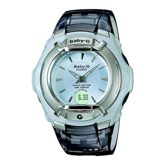
Summary of Contents for Casio QW-3390
- Page 1 ERVICE ANUAL & PARTS LIST REF. NO. S/M-891 APR. 2005 MODULE NO. QW-3390 BGT-3010 Ver.1 : May. 2006 INDEX (WITHOUT PRICE)
-
Page 2: Table Of Contents
CONTENTS Page 1. SPECIFICATIONS: MODULE QW-3390 ............ 1 2. OPERATION CHART: MODULE QW-3390 ..........2 3. DRAWINGS: MODULE QW-3390 3-1. LCD DIAGRAM ..................... 8 3-2. CIRCUIT DIAGRAM ..................9 3-3. CHECKING TERMINALS AND COMPONENTS ......... 10 4. EXPLODED VIEW: MODULE QW-3390 ........... 11 5. -
Page 3: Specifications: Module Qw-3390
1. SPECIFICATIONS: MODULE QW-3390 Item Detail Battery CR1616 Battery life Approx. 2 years 0.5 µA maximum Current consumption Alarm system Piezo plate on Cover/Back ±15 sec./month Accuracy Accuracy setting system Trimmer capacitor Accuracy checking See page 14 Functions • Time calibration signal reception... -
Page 4: Operation Chart: Module Qw-3390
2. OPERATION CHART: MODULE QW-3390 — 2 —... - Page 5 — 3 —...
- Page 6 — 4 —...
- Page 7 — 5 —...
- Page 8 — 6 —...
- Page 9 — 7 —...
-
Page 10: Drawings: Module Qw-3390
3. DRAWINGS: MODULE QW-3390 3-1. LCD DIAGRAM DST0 X8Y4 X8Y3 X8Y2 X8Y1 X8Y0 X9Y4 X9Y3 X9Y2 X9Y1 X9Y0 X10Y4 X10Y3 X10Y2 X10Y1 X10Y0 X11Y4 X11Y3 X11Y2 X11Y1 X11Y0 X16Y4 X16Y3 X16Y2 X16Y1 X16Y0 X15Y4 X15Y3 X15Y2 X15Y1 X15Y0 X14Y4 X14Y3... -
Page 11: Circuit Diagram
3-2. CIRCUIT DIAGRAM — 9 —... -
Page 12: Checking Terminals And Components
3-3. CHECKING TERMINALS AND COMPONENTS CUSHION 506 (7211 9631) LED2 COIL LEDOUT COIL VOUT COIL LEDOUT VDD2 VDD3 LEDOUT VOUT VOUT LED1 VDD2 VOUT VDD2 VOUT LED2 VDD2 SCIN LED1 VOUT SCIN SCIN 16. PCB ASS'Y LEDOUT (7640 7974) LEDOUT LED3 LED3 FET-S... -
Page 13: Exploded View: Module Qw-3390
4. EXPLODED VIEW: MODULE QW-3390 9 (1015 5782) 7 (1001 4042) 7 (1001 4042) Casing parts: DIAL SPACER 18 (1012 3230) 11 (1015 5789) 24 (7224 0652) 25 (1015 5787) 1 (7640 7573) 17 (7228 0511) 3 (1013 0977) 17 (7228 0511) -
Page 14: Parts List: Module Qw-3390
5. PARTS LIST: MODULE QW-3390 Note: 1. Prices and specifications are subject to change without prior notice. 2. Spare parts are classified as follows according to their importance in after-sales service. A Rank ---------------------------------------- Very Important B Rank ---------------------------------------- Important C Rank ---------------------------------------- Less important 3. -
Page 15: Precautions For Repair: Module Qw-3390
6. PRECAUTIONS FOR REPAIR: MODULE QW-3390 6-1. AC (ALL CLEAR) AND REMOVING OF MODULE 1. Perform AC (ALL CLEAR) when inserting a new battery, or else the memories and/ or counters may give erratic displays. Touch the AC contact and the main plate with the metallic tweezers. -
Page 16: Accuracy Checking
NOTE: The “ACCURACY CHECKING MODE” will automatically return to the regular mode QW-3390 in 1 ~ 2 hour(s) without any operation. 6-3. TIME CALIBRATION SIGNAL TEST MODE 1) Press B, C and D button at the same time to enter the test mode. -
Page 17: Troubleshooting: Module Qw-3390
7. TROUBLESHOOTING: MODULE QW-3390 This is a flow chart about signal reception. START Check whether the Home City code is selected correctly. To perform MANUAL time calibration signal reception Signal reception OK? To perform AUTO time calibration signal reception Signal... - Page 18 Ver. 1 : May. 2006 Correction of pages 11 and 12 CASIO COMPUTER CO.,LTD. Overseas Service Division 6-2, Hon-machi 1-Chome Shibuya-ku, Tokyo 151-8543, Japan...


Need help?
Do you have a question about the QW-3390 and is the answer not in the manual?
Questions and answers