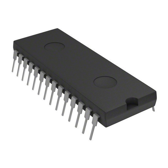
Summary of Contents for Philips TDA8303
- Page 1 DATA SHEET TDA8303 TDA8303A Small signal combination IC for black/white TV Preliminary specification File under Integrated Circuits, IC02 INTEGRATED CIRCUITS July 1992...
- Page 2 The TDA8303 is for applications with npn tuners and the TDA8303A for pnp tuners. FUNCTIONAL DESCRIPTION Video IF amplifier, demodulator and video amplifier...
- Page 3 Philips Semiconductors Small signal combination IC for black/white TV QUICK REFERENCE DATA SYMBOL Supply positive supply voltage (pin 7) supply current (pin 7) start current (pin 11) start Video IF sensitivity (RMS value) 8-9(RMS) IF gain control range signal-to-noise ratio...
- Page 4 Philips Semiconductors Small signal combination IC for black/white July 1992 Preliminary specification TDA8303 TDA8303A...
- Page 5 flyback input phase 2 detector AGC circuit The AGC circuit of the TDA8303/TDA8303A is a top-sync detector. The video signal coming from the video amplifier passes a 2nd order low-pass filter before it is compared with an internal reference level. The comparator stage is...
-
Page 6: Limiting Values
Philips Semiconductors Small signal combination IC for black/white TV Narrow window mode: divider ratio between 522 and 528 (60 Hz); or 622 and 628 (50 Hz). The divider system switches over to narrow window mode when the up/down counter has reached his... - Page 7 Philips Semiconductors Small signal combination IC for black/white TV CHARACTERISTICS = 12 V;T = 25 C; carrier 38.9 MHz negative modulation, unless otherwise specified SYMBOL PARAMETER Supply (pin 7) supply voltage range supply current start current (pin 11) start voltage horizontal oscillator start protection level IF Amplifier (pins 8 and 9)
- Page 8 Philips Semiconductors Small signal combination IC for black/white TV SYMBOL PARAMETER signal-to-noise ratio signal-to-noise ratio residual carrier signal residual 2nd harmonic of carrier signal Tuner AGC minimum starting point for tuner take over 8-9(RMS) (RMS value) maximum starting point for tuner take over...
- Page 9 Philips Semiconductors Small signal combination IC for black/white TV SYMBOL PARAMETER Sound circuit (note 12) input limiting voltage input resistance input capacitance AM suppression AF output signal (RMS value) 12(RMS) AF output signal when pin 11 is used as a...
- Page 10 Philips Semiconductors Small signal combination IC for black/white TV SYMBOL PARAMETER ECOND CONTROL LOOP POSITIVE EDGE control sensitivity ------- control range HASE ADJUSTMENT VIA SECOND CONTROL LOOP control sensitivity maximum allowed phase shift ORIZONTAL OSCILLATOR free running frequency spread with fixed external components frequency variations with supply voltage from 9.5 to 13.2 V...
- Page 11 Philips Semiconductors Small signal combination IC for black/white TV SYMBOL PARAMETER Vertical circuit (note 24) ERTICAL RAMP GENERATOR input current during scan discharge current during retrace sawtooth amplitude (peak-to-peak value) 2(p p) interlace timing of the internal pulses ERTICAL OUTPUT...
- Page 12 Philips Semiconductors Small signal combination IC for black/white TV connected to the supply. The reference circuit must be tuned in such a way that the output is symmetrical clipping at maximum volume. 13. The test set-up is illustrated by Fig.6. The AM rejection curve (typical) is illustrated by Fig.7.
- Page 13 Philips Semiconductors Small signal combination IC for black/white TV handbook, full pagewidth handbook, full pagewidth MBC211 July 1992 MLA667 17.5% Fig.2 Video output signal. Fig.3 EBU test signal waveform (line 330). Preliminary specification TDA8303A 100% 100% TDA8303...
- Page 14 Philips Semiconductors Small signal combination IC for black/white TV handbook, full pagewidth 33.4 MHz handbook, full pagewidth 30 dB SC CC Input signal conditions SC = Sound carrier CC = Chrominance carrier PC = Picture carrier All with respect to top sync level at 4.4 MHz...
- Page 15 Philips Semiconductors Small signal combination IC for black/white TV Fig.5 Signal-to-noise ratio as a function of the input voltage (0 dB = 100 mV). July 1992 Fig.6 Test set-up AM suppression. Preliminary specification TDA8303 TDA8303A...
- Page 16 Philips Semiconductors Preliminary specification TDA8303 Small signal combination IC for black/white TV TDA8303A Fig.7 AM suppression. Fig.8 Volume control characteristics. July 1992...
- Page 17 Philips Semiconductors Preliminary specification TDA8303 Small signal combination IC for black/white TV TDA8303A Fig.9 Timing diagram. July 1992...
- Page 18 Philips Semiconductors Small signal combination IC for black/white TV Table 1 Switching levels coincidence detector CONDITION 6.7 V strong signal weak signal 5.7 V strong signal weak signal July 1992 CONTROL SENSITIVITY HORIZONTAL OSCILLATOR (kHz/ S) T2 - T1 11.3 11.3...
- Page 19 Philips Semiconductors Preliminary specification TDA8303 Small signal combination IC for black/white TV TDA8303A Fig.12 Application diagram. July 1992...
-
Page 20: Package Outline
Philips Semiconductors Small signal combination IC for black/white TV PACKAGE OUTLINE DIP28: plastic dual in-line package; 28 leads (600 mil) handbook, full pagewidth pin 1 index DIMENSIONS (inch dimensions are derived from the original mm dimensions) UNIT max. min. max. -
Page 21: Life Support Applications
Philips customers using or selling these products for use in such applications do so at their own risk and agree to fully indemnify Philips for any damages resulting from such improper use or sale.


Need help?
Do you have a question about the TDA8303 and is the answer not in the manual?
Questions and answers