Table of Contents
Advertisement
Available languages
Available languages
Advertisement
Table of Contents

Subscribe to Our Youtube Channel
Related Manuals for Pentair RAYCHEM RAYSTAT-ECO-10


Summary of Contents for Pentair RAYCHEM RAYSTAT-ECO-10
- Page 1 RAYSTAT-ECO-10 EnErgy-saving frEEzE protEction controllEr EnErgiEsparEndEs stEuErgErät für frostschutzanwEndungEn régulatEur économiquE pour la misE hors gEl unità di controllo antigElo a risparmio EnErgEtico Thermal BUIlDING solUTIoNs Raychem-IM-INST196-RAYSTATECO10-ML-1701...
-
Page 2: Table Of Contents
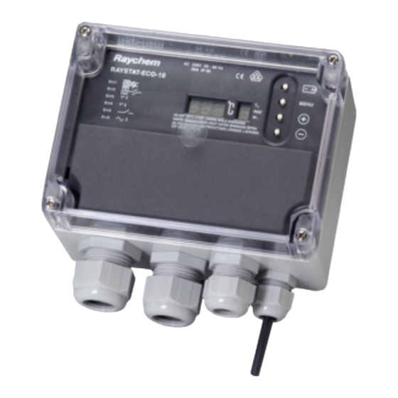
eNGlIsh Table of contents ..................2 Description & Technical data ..............6 Functional description ................7 Display ..................... 7 Installation description ................8 Operational description ................11 Testing, commissioning and maintenance ..........14 Wiring diagrams ..................42 Commissioning sheet ................45 DeUTsch Inhaltsverzeichnis .................. - Page 5 eNGlIsh a 1. Thermostat enclosure B 1. Terminal screwdriver 3 mm 2, 3, 4, 5. Cable entries 2. Posi-drive screwdriver (2 x M25, 1 x M20, 1 x M16) 5 mm 6. Temperature sensor Pt 100 3. Trimming knife 7. Sensor cable 4, 5, 6.
- Page 6 RAYSTAT-ECO-10 is necessary. Installation and all wiring must be in accordance with applicable regulations. The device must be installed in non hazardous areas only. Pentair Thermal Management offers other controls for use in hazardous areas. Technical data Supply voltage: 230 Vac.
-
Page 7: Functional Description
T sensor Type: 3-wire Pt 100 according to IEC Class B Sensor head: 50 mm x Ø 6 mm * An external Pt 100 sensor can be connected, the sensor cable can be extended with a 3-core shielded cable of 20 Ω max. per conductor (e.g. up to 150 m with a 3 x 1.5 mm²... -
Page 8: Installation Description
For selection of industrial heating cables, follow the Selection Guide for Industrial Trace-Heating Systems or use the latest version of TraceCalc or contact Pentair Thermal Management. Follow the design guidelines and install the system in accordance with the system specifications. - Page 9 Failure to remove the wire links can result in damage to the unit or to other connected equipment. Wiring of RAYSTAT-ECO-10 to a remote alarm is optional through the M20 gland 4 . Pentair Thermal Management strongly recommends the use of a remote alarm for critical operations (e.g.
- Page 10 4. Installation of the sensor location of the sensor Mount the sensor in a position exposed to normal weather conditions but shielded from direct sunlight. The sensor should not be located against surfaces that are heated from within or may be heated by sunlight. If the RAYSTAT-ECO-10 is located outdoors, the sensor cable may be shatened and the sensor may be mounted directly to the bottom of the housing, but make sure that at least 35 - 40 mm of the sensor extends beyond the...
-
Page 11: Operational Description
operaTIoNal DescrIpTIoN 1. Introduction The RAYSTAT-ECO-10 parameters are configured via a menu system. The unit is delivered with a battery so that the operating parameters can be set up without any need for the power supply to be connected. This is useful for setting units on the bench prior to mounting in their working location or on site when power isn’t available. - Page 12 3. parameters The first parameter to show up during Set-up mode is the Set Point. Other parameters, their default, minimum and maximum values are shown in the below table: Default Displayed parameter min. max. value code Set Point (°C) Min. Expected Ambient (°C) Pipe Size Heater Operation if Sensor Error...
-
Page 14: Testing, Commissioning And Maintenance
TesTING, commIssIoNING aND maINTeNaNce Test heating cable when thermostat installation is complete as directed in the instructions applicable for the heating cable. Fill out the commisioning sheet (page 3514). Maintain thermostat during normal plant maintenance. Check: • Mounting is firm • Exposed sensor cable is not damaged • Glands are tightened firmly • Thermostat operation is correct (no error code displayed) - Page 15 Die Installation und der Anschluss des Steuergerätes müssen entsprechend den örtlich geltenden Bestimmungen erfolgen. Das Steuergerät RAYSTAT-ECO-10 darf nicht in explosionsgefährdeten Bereichen installiert werden. Für explosionsgefährdete Bereiche bietet Pentair Thermal Management spezielle Steuergeräte an. Technische Daten Betriebsspannung: AC 230V, +10%/–10%, 50/60 Hz (inkl.
-
Page 16: Funktionsbeschreibung
Gehäuse Umgebungstemperatur- bereich: –40°C bis +80°C Schutzart: IP65 Bohrungen: 2 x M25, 1 x M20, 1 x M16 Abmessungen: 120 x 160 x 90 mm Gewicht: ca. 800 g Material: Graues Polycarbonat Deckelbefestigung: 4 x M6, Zylinderkpfschrauben - rostfreier Stahl Montage: Wandmontage oder auf Befestigungswinkel SB-100/SB-101... -
Page 17: Display
Bei einer Störung schaltet das Alarmrelais, und in der Anzeige erscheint eine Fehlermeldung. Sie können außerdem eingeben, ob das Begleitheizsystem bei einem Sensorausfall abschalten oder weiter in Betrieb bleiben soll (EIN oder AUS). Das Steuergerät ist zusätzlich mit einer Batterie (im Lieferumfang) ausgestattet, so dass die Programmierung auch ohne Netzspannungsanschluss vorgenommen werden kann (siehe „Programmierung“... -
Page 18: Montage
Informationen zur Auswahl und Auslegung von Frostschutzsystemen in der Bautechnik finden Sie in unserem Technischen Handbuch. Eine detaillierte Auswahlhilfe für industrielle Begleitheizsysteme von Pentair Thermal Management finden Sie in unserer Projektierungsanleitung für industrielle Begleitheizsysteme, bzw. in unserer speziell entwickelten Planungssoftware „TraceCalc“. Für Fragen zu Ihrer individuellen Anwendung wenden Sie sich bitte direkt an Ihre Pentair Thermal Management-Vertretung. - Page 19 Komponenten beschädigt werden können. Über die M20-Verschraubung (4) kann das Steuergerät RAYSTAT-ECO-10 auch an eine externe Alarmeinheit angeschlossen werden. Für Anwendungen mit speziellen Anforderungen empfiehlt Pentair Thermal Management den Einsatz einer externen Alarmeinheit (z.B. bei extrem niedrigen Umgebungstemperaturen (unter –25°C) oder kritischen Prozessen).
-
Page 20: Programmierung
5. Fertigstellung der montage Bringen Sie die Gehäuseabdeckung wieder an. Wenn Sie das Steuergerät RAYSTAT-ECO-10 noch nicht programmiert haben, folgen Sie nun den Hinweisen im Kapitel „Programmierung“ auf Seite 20. Schließen Sie den Deckel des Gehäuses. FUNkTIoNsBeschreIBUNG 1. einleitung Die RAYSTAT-ECO-10 Parameter sind über ein System-Menü einstellbar. Das Steuergerät ist zusätzlich mit einer Batterie ausgestattet, so dass die Programmierung auch ohne Netzspannungsanschluss erfolgen kann. - Page 21 Wenn das Steuergerät auf seine Werkseinstellungen zurückgesetzt werden soll, dann drücken Sie gleichzeitig die Tasten + und – für ca. 2 Sekunden. Im Display erscheint anschließend (Default). 3. parameter Der erste angezeigte Parameter im Display während des Programmiermodus ist die Haltetemperatur. Andere Parameter, Werkseinstellungen, Minimum- und Maximumwerte können aus der folgenden Tabelle entnommen werden.
-
Page 23: Test, Inbetriebnahme Und Wartung
TesT, INBeTrIeBNahme UND WarTUNG Nachdem Sie das Steuergerät montiert haben, prüfen Sie, ob das Heizband ordnungsgemäß funktioniert. Hinweise zur Überprüfung finden Sie in der Montageanleitung des Heizbandes. Nun füllen Sie das Inbetriebnahmeprotokoll aus (Seite 35). Das Steuergerät sollte in regelmäßigen Abständen gewartet werden. Prüfen Sie, ob • das Steuergerät fest montiert ist • das Sensorkabel beschädigt wurde... - Page 24 RAYSTAT-ECO-10. Installation et câblage doivent être conformes aux réglementations en vigueur. Le régulateur est prévu pour une installation en zone ordinaire uniquement. La gamme Pentair Thermal Management comprend d’autres dispositifs de régulation pour les zones explosibles. caractéristiques techniques Tension d’alimentation: 230 Vca +10%/–10%, 50/60 Hz...
-
Page 25: Fonctionnement
Boîtier Température de service: –40°C à +80°C Protection: IP 65 Entrées: 2 x M25, 1 x M20, 1 x M16 Dimensions: 20 x 160 x 90 mm Poids approx.: 800 g Matériau: polycarbonate Montage: sur paroi ou support du fixation sur la tuyauterie SB-100 / SB-101 sonde de température Type:... -
Page 26: Afficheur
En cas d’hésitation à propos du réglage adéquat, il vaut mieux choisir une valeur trop élevée que trop basse pour éviter tout risque de gel des conduites. En cas d’erreur, le relais d’alarme est sollicité et un code d’erreur est donné... -
Page 27: Installation
Pour les rubans chauffants destinés à l’industrie, voir le Guide de sélection industrie, utiliser la dernière version du logiciel TraceCalc ou encore prendre contact avec votre agent Pentair Thermal Management. Respecter la marche à suivre et procéder à l’installation en conformité... - Page 28 équipement connecté. Le raccordement du RAYSTAT-ECO-10 à une alarme à distance est une option qui utilise le presse-étoupe 4 (M20). Pentair Thermal Management recommande vivement une alarme distante pour les applications critiques, lorsque des températures basses extrêmes sont à envisager (inférieures à –25°C) ou pour des procédés thermosensibles.
-
Page 29: Paramétrage
remarque: le câble de la sonde peut être prolongé jusqu’à 150 m avec un câble de section 3 x 1,5 mm2. Raccorder cette prolongation dans une boîte de jonction JB-86 ou dispositif équivalent. Utiliser un câble blindé pour éviter les interférences. La tresse de blindage doit être reliée à la prise de terre du régulateur. - Page 30 Pour mettre le thermostat en mode de paramétrage lorsque l’appareil est raccordé à l’alimentation électrique (l’afficheur indique alternativement le point de consigne et la valeur de température mesurée), appuyer sur la touche MENU pendant 2 secondes environ. Parcourir la liste complète des paramètres effectués en appuyant successivement sur la touche Menu.
-
Page 32: Test, Mise En Service Et Entretien
TesT, mIse eN serVIce eT eNTreTIeN Procéder à l’essai du ruban chauffant à la fin de l’installation du régulateur conformément aux instructions de Pentair Thermal Management concernant le ruban chauffant. Compléter la fiche de mise en service (page 35). Vérifier et entretenir le régulateur lors de la maintenance régulière des installations. - Page 33 RAYSTAT-ECO-10. L’installazione e i collegamenti elettrici devono essere eseguiti in conformità alle norme applicabili. Il dispositivo può essere installato solo in aree non pericolose. Pentair Thermal Management offre altre unità di controllo idonee all’utilizzo in zone pericolose.
-
Page 34: Descrizione Funzionale
sensore di temperatura Tipo: Pt 100 a 3 fili, conforme alla norma IEC Classe B Testa del sensore: 50 mm x Ø 6 mm * È possibile collegare un sensore Pt 100 esterno; il cavo del sensore può essere prolungato con un cavo schermato a 3 conduttori da 20 Ω max. per conduttore (es. -
Page 35: Procedura Di Installazione
Per la selezione dei cavi scaldanti da utilizzare in applicazioni industriali, seguire la guida alla selezione dei sistemi di tracciamento elettrico industriali o usare l’ultima versione di TraceCalc, oppure contattare Pentair Thermal Management. Seguire le linee guida per la progettazione e installare il sistema attenendosi alle specifiche riportate. - Page 36 Montare l’involucro mediante tasselli (a vite) usando i quattro fori con Ø 4 mm. Installazione su tubazioni Pentair Thermal Management offre diverse staffe di supporto (non incluse) per l’installazione dell’unità RAYSTAT-ECO-10 su una tubazione: SB-100 o SB-101. 3. cablaggio Rimuovere la copertura di protezione dei terminali.
- Page 37 4. Installazione del sensore posizione del sensore Installare il sensore in una posizione esposta a condizioni atmosferiche normali ma al riparo dalla luce diretta del sole. Il sensore non deve essere collocato contro superfici che siano riscaldate dall’interno o che possano essere riscaldate dalla luce solare.
-
Page 38: Descrizione Operativa
DescrIzIoNe operaTIVa 1. Introduzione I parametri dell’unità RAYSTAT-ECO-10 devono essere configurati attraverso un sistema a menu. Il dispositivo è provvisto di una batteria interna, che consente di configurare i parametri operativi senza bisogno di collegare l’unità all’alimentazione elettrica. Questo è particolarmente utile per configurare le unità... - Page 39 3. parametri Il primo parametro che compare quando si attiva la modalità di configurazione è il setpoint. La tabella qui sotto mostra gli altri parametri, i rispettivi valori predefiniti e le impostazioni minime e massime consentite: Valore codice parametro min. max.
-
Page 41: Collaudo, Messa In Servizio E Manutenzione
collaUDo, messa IN serVIzIo e maNUTeNzIoNe Dopo l’installazione del termostato, collaudare il cavo scaldante come descritto nelle istruzioni del prodotto. Compilare la scheda di messa in servizio (pag. 3541). Eseguire la manutenzione del termostato durante la normale manutenzione dell’impianto. Controllare: • La solidità... -
Page 42: Schemi Elettrici
a. Wiring Diagrams anschlussdiagramm schémas électriques schemi elettrici Max. C 25 A 30 mA RAYSTAT-ECO-10 5 L L 8 N N A B C alarm* 2A max. R: Same colour R: die gleiche Farbe R: la même couleur R: Stesso colore Heating cable Temp. - Page 43 B. Voltage free operation: remove links W1 and W2 and change “U” parameter in set up mode from “0” (not volt free) to “1” (volt free) as explained on page 12 of this manual. potentialfreier Berieb: entfermen sie die Brücken W1 und W2 und ändern sie die den parameter für potentialfreien Betrieb “U”...
- Page 46 Fax +7 495 926 18 86 salesee@pentair.com saleskz@pentair.com www.pentairthermal.com Pentair is owned by Pentair or its global affiliates. All other trademarks are the property of their respective owners. Pentair reserves the right to change specifications without prior notice. © 2015-2017 Pentair. Thermal BUIlDING solUTIoNs...
Need help?
Do you have a question about the RAYCHEM RAYSTAT-ECO-10 and is the answer not in the manual?
Questions and answers