
Related Manuals for Atlas TSD-DA28


Summary of Contents for Atlas TSD-DA28
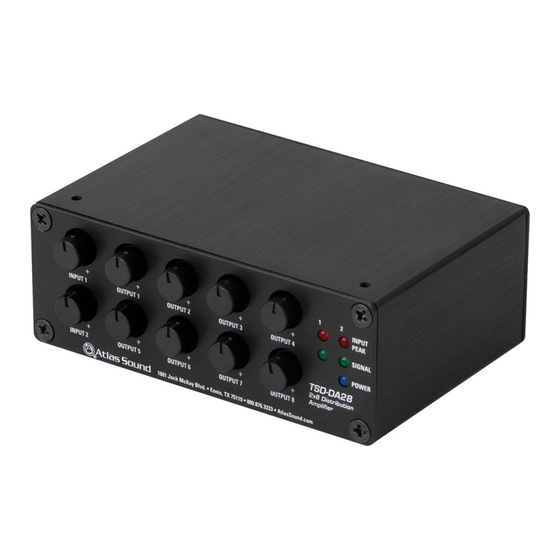
- Page 1 TSD-DA28 Owner’s Manual 2x8 Distribution Amplifier TSD-DA28 2x8 Balanced Line Distribution Amplifier – 1 – AtlasSound.com Specifications are subject to change without notice.
-
Page 2: Audio Applications
1 in / 8 out configuration. The TSD-DA28 is part of a full line of Atlas Sound Time Saving Devices. These compact (1.5" x 4" x 2.75") units are designed to solve some of the common audio system problems in the easiest and in the most efficient and cost-effective way. -
Page 3: Front Panel Description
TSD-DA28 Owner’s Manual 2x8 Distribution Amplifier Front Panel Description 1. Input Level Controls - Adjust the gain of the source audio signal that is applied to the DA28 circuitry. Turn clockwise to increase the signal level and counter-clockwise to decrease it. -
Page 4: Rear Panel Description
TSD-DA28 Owner’s Manual 2x8 Distribution Amplifier Rear Panel Description TSD Input/Output connections are removable for easy system wiring. The connector has a 3.5mm pitch between pins. 1. DC Power Input - Each TSD that requires DC power comes with a 2 position connector for an external 24VDC power supply (sold separately). - Page 5 TSD-DA28 Owner’s Manual 2x8 Distribution Amplifier Knob and Security Cover All front panel level controls feature a removable knob that can be replaced with an included security cover. Follow these steps to prevent potentiometer damage or unwanted changes. 1. Knob Installation - Turn the potentiometer shaft fully counter-clockwise. Align the knob indicator to the lowest setting on the panel and the potentiometer shaft slot.
-
Page 6: Block Diagram
TSD-DA28 Owner’s Manual 2x8 Distribution Amplifier Block Diagram – OUTPUT 1 OUTPUT 1 LEVEL ON FRONT PANEL SIGNAL PEAK – OUTPUT 2 OUTPUT 2 LEVEL ON FRONT PANEL INPUT 1 – INPUT 1 LEVEL – OUTPUT 3 ON FRONT PANEL... - Page 7 TSD-DA28 Owner’s Manual 2x8 Distribution Amplifier Controls Indicators Input Signal Green, 25mV On Threshold Power Blue Electrical .06% & 1kHz Signal to Noise 90dB Mounting Velcro™ Industrial Grade, Included Brackets Qty 2, Included Power Requirements Voltage 24VDC Power Consumption 80mA...
-
Page 8: Limited Warranty
SOUND brand products except as follows: one year on electronics and control systems; one year on fuses and lamps carry no warranty. Atlas Sound will solely at its discretion, replace at no charge or repair free of charge defective parts or products when the product has been applied and used in... - Page 9 To TV 1 Right Audio In ©2011 Atlas Sound L.P. All rights reserved. Atlas Sound is a trademark of Atlas Sound L.P. All other trademarks are the property of their respective owners. All specs are subject to change without notice. ATS004211 RevA 9/11 AtlasSound.com...
- Page 10 Press Feed Out 5 ©2011 Atlas Sound L.P. All rights reserved. Atlas Sound is a trademark of Atlas Sound L.P. All other trademarks are the property of their respective owners. All specs are subject to change without notice. ATS004211 RevA 9/11 AtlasSound.com...
- Page 11 TSD-DA28 2 x 8 Distribution Amplifier Atlas Time Saving Devices INPUT – – – – – PEAK INPUT 1 OUTPUT 1 OUTPUT 2 OUTPUT 3 OUTPUT 4 SIGNAL POWER TSD-DA28 – – – – – 2x8 Distribution Amplifier INPUT 2...
- Page 12 Specifications Description Chassis Color Chassis Material Inputs Outputs Controls Indicators Electrical Mounting Power Requirements Dimensions Weight Accessories Safety and Certifications 1601 JACK MCKAY BLVD. ENNIS, TEXAS 75119 U.S.A. AtlasSound.com TELEPHONE: (800) 876-3333 FAX (800) 765-3435...
- Page 13 Block Diagram – OUTPUT 1 OUTPUT 1 LEVEL ON FRONT PANEL SIGNAL PEAK – OUTPUT 2 OUTPUT 2 LEVEL ON FRONT PANEL INPUT 1 – INPUT 1 LEVEL – OUTPUT 3 ON FRONT PANEL OUTPUT 3 LEVEL ON FRONT PANEL –...
Need help?
Do you have a question about the TSD-DA28 and is the answer not in the manual?
Questions and answers