Siemens SIMATIC ET 200SP Product Information
Hide thumbs
Also See for SIMATIC ET 200SP:
- System manual (320 pages) ,
- Manual (270 pages) ,
- Operating instructions manual (166 pages)
Table of Contents
Advertisement
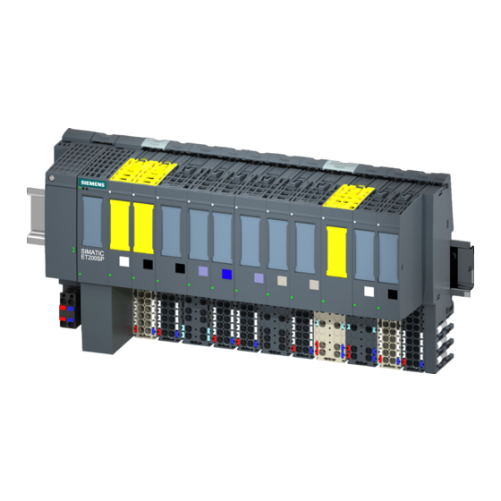
ET 200SP distributed I/O system
SIMATIC
ET 200SP
ET 200SP distributed I/O system
Product Information
Translation of original operating instructions
07/2013
A5E32288220-AA
___________________
Preface
___________________
Product overview
___________________
Application planning
___________________
Installation
___________________
Connecting
___________________
Configuring
___________________
Maintenance
___________________
Technical specifications
___________________
Accessories/spare parts
1
2
3
4
5
6
7
8
Advertisement
Table of Contents

Related Manuals for Siemens SIMATIC ET 200SP


Summary of Contents for Siemens SIMATIC ET 200SP
- Page 1 ___________________ ET 200SP distributed I/O system Preface ___________________ Product overview ___________________ Application planning SIMATIC ___________________ Installation ET 200SP ___________________ ET 200SP distributed I/O system Connecting ___________________ Configuring Product Information ___________________ Maintenance ___________________ Technical specifications ___________________ Accessories/spare parts Translation of original operating instructions 07/2013 A5E32288220-AA...
- Page 2 Note the following: WARNING Siemens products may only be used for the applications described in the catalog and in the relevant technical documentation. If products and components from other manufacturers are used, these must be recommended or approved by Siemens. Proper transport, storage, installation, assembly, commissioning, operation and maintenance are required to ensure that the products operate safely and without any problems.
-
Page 3: Preface
Preface Scope of the product information This product information amends the ET 200SP Distributed I/O System System Manual (http://support.automation.siemens.com/WW/view/en/58649293) to include ET 200SP fail- safe modules. ET 200SP distributed I/O system Product Information, 07/2013, A5E32288220-AA... - Page 4 Preface ET 200SP distributed I/O system Product Information, 07/2013, A5E32288220-AA...
-
Page 5: Table Of Contents
Table of contents Preface ..............................3 Product overview ............................ 7 What are fail-safe automation systems and fail-safe modules? ............ 7 Fault reactions with fail-safe modules ..................10 Application planning ..........................13 Forming potential groups with fail-safe modules ................. 13 Installation ............................15 Basics ............................ - Page 6 Table of contents ET 200SP distributed I/O system Product Information, 07/2013, A5E32288220-AA...
-
Page 7: Product Overview
Product overview What are fail-safe automation systems and fail-safe modules? Fail-safe automation systems Fail-safe automation systems (F-systems) are used in systems with higher-level safety requirements. F-systems serve to control processes and ensure that they are in a safe state immediately after shutdown. In other words, F-systems control processes in which an immediate shutdown does not endanger persons or the environment. - Page 8 Product overview 1.1 What are fail-safe automation systems and fail-safe modules? Achievable safety classes Fail-safe modules are equipped with integrated safety functions for safety mode. The following safety classes can be achieved through appropriate parameter assignment of the safety functions in STEP 7 Professional V12 SP1 or higher with STEP 7 Safety Advanced optional package V12 or higher, through a specific combination of fail-safe and standard modules, and through a specific arrangement and wiring of sensors and actuators: Safety class in safety mode...
- Page 9 Product overview 1.1 What are fail-safe automation systems and fail-safe modules? SIMATIC Safety F-system with ET 200SP The following figure shows a sample configuration for a SIMATIC Safety F-system with, among other things, an ET 200SP on a PROFINET IO. The PROFINET IO lines can be set up with copper cable, with fiber-optic cable or WLAN.
-
Page 10: Fault Reactions With Fail-Safe Modules
Product overview 1.2 Fault reactions with fail-safe modules Fault reactions with fail-safe modules Safe state (safety concept) The basic principle behind the safety concept is the existence of a safe state for all process variables. Note For digital F-modules, this safe state is the value "0". This applies to both sensors and actuators. - Page 11 For additional information on passivation and reintegration of F-I/O, refer to the SIMATIC Safety, Configuring and Programming (http://support.automation.siemens.com/WW/view/en/54110126) manual. Reaction of the F-module with inputs to communication errors F-modules with inputs respond differently to communication errors compared to other errors.
- Page 12 Product overview 1.2 Fault reactions with fail-safe modules ET 200SP distributed I/O system Product Information, 07/2013, A5E32288220-AA...
-
Page 13: Application Planning
Application planning Forming potential groups with fail-safe modules Introduction ET 200SP distributed I/O systems can be configured using fail-safe and non-fail-safe modules. This chapter provides an example of a mixed configuration comprising fail-safe and non-fails-safe modules. Assembly example for ET 200SP with fail-safe and non-fail-safe modules Generally speaking, it is not necessary to operate fail-safe and non-fail-safe modules in separate potential groups. - Page 14 Application planning 2.1 Forming potential groups with fail-safe modules ET 200SP distributed I/O system Product Information, 07/2013, A5E32288220-AA...
-
Page 15: Installation
Installation Basics The following applies to ET 200SP fail-safe modules: WARNING Protection from conductive contaminants In consideration of the environmental conditions, the devices must be protected from conductive contaminants. One way to accomplish this is by installing the devices in a control cabinet with an appropriate degree of protection. - Page 16 Installation 3.1 Basics ET 200SP distributed I/O system Product Information, 07/2013, A5E32288220-AA...
-
Page 17: Connecting
Connecting Additional rules and provisions for operation of the ET 200SP with fail-safe modules 4.1.1 Safe functional extra-low voltage (SELV) for fail-safe modules WARNING The fail-safe modules must be operated with safe functional extra low voltage (SELV, PELV). You can find more information on safe functional extra-low voltage in the data sheets, for example, of the applicable power supplies. -
Page 18: Requirements Of Sensors And Actuators For Fail-Safe Modules
(230 V AC → 24 V DC) with a mains buffering time of at least 20 ms. The latest up-to-date information on PS components is available on the Internet (http://mall.automation.siemens.com). It goes without saying that these requirements also apply to power packs/power supply units not constructed using ET 200SP / S7-300/-400/-1500 technology. - Page 19 Connecting 4.1 Additional rules and provisions for operation of the ET 200SP with fail-safe modules Additional sensor requirements General rule: To achieve SIL3/Cat.3/PLe, a single-channel sensor is all you need. However, to achieve SIL3/Cat.3/PLe with a single-channel sensor, the sensor itself must be SIL3/Cat.3/PLe-capable;...
-
Page 20: Capacitive Crosstalk Of Digital Input/Output Signals
Connecting 4.1 Additional rules and provisions for operation of the ET 200SP with fail-safe modules Additional requirements for actuators The fail-safe output modules test the outputs at regular intervals. The F-module briefly switches off the activated outputs and, if necessary, switches on the deactivated outputs. You can assign the maximum duration of the test pulses (dark and light period) with parameters. -
Page 21: Configuring
The actual configuration can then differ from the specified configuration. For additional information on assigning the F-destination address, refer to the SIMATIC Safety - Configuring and Programming (http://support.automation.siemens.com/WW/view/en/54110126) programming and operating manual. ET 200SP distributed I/O system Product Information, 07/2013, A5E32288220-AA... - Page 22 Configuring 5.1 Assigning the F-destination address for fail-safe modules ET 200SP distributed I/O system Product Information, 07/2013, A5E32288220-AA...
-
Page 23: Maintenance
Maintenance Firmware update Introduction It may be necessary to update the firmware during operation (e.g. function expansions). Update the firmware of the interface module and I/O modules using firmware files. Options for the firmware update Online via PROFINET IO/PROFIBUS DP (with STEP 7) Requirements The ET 200SP is accessible online via PROFINET IO/PROFIBUS DP. - Page 24 Maintenance 6.1 Firmware update See also Certificate (http://support.automation.siemens.com/WW/view/en/49368678/134200) ET 200SP distributed I/O system Product Information, 07/2013, A5E32288220-AA...
-
Page 25: Technical Specifications
In particular, this involves structural measures in the building design phase. For detailed information regarding overvoltage protection, we recommend that you contact your Siemens representative or a company specializing in lightning protection. ET 200SP distributed I/O system Product Information, 07/2013, A5E32288220-AA... - Page 26 Technical specifications 7.1 Electromagnetic compatibility of fail-safe modules The following figure shows an example configuration with fail-safe modules. Voltage is supplied by 1 power supply unit. Note, however, that the total current of the modules fed by the power supply unit must not exceed the permissible limits. You can also use multiple power supply units.
-
Page 27: Standards And Approvals
● 94/9/EC "Equipment and Protective Systems Intended for Use in Potentially Explosive Atmospheres" (Explosion Protection Directive) The EC declarations of conformity are kept available for the relevant authorities at: Siemens Aktiengesellschaft Industry Sector I IA AS FA DH AMB PO Box 1963... - Page 28 Technical specifications 7.2 Standards and approvals ET 200SP distributed I/O system Product Information, 07/2013, A5E32288220-AA...
-
Page 29: Accessories/Spare Parts
Be sure to observe the detailed information on lightning protection and overvoltage protection of the ET 200SP distributed I/O device in ET 200SP distributed I/O system (http://support.automation.siemens.com/WW/view/en/58649293). Components for overvoltage protection of fail-safe modules (lightning protection zone transition to 1) - Page 30 Accessories/spare parts 8.1 Lightning protection and overvoltage protection for fail-safe modules ET 200SP distributed I/O system Product Information, 07/2013, A5E32288220-AA...
-
Page 31: Glossary
Glossary 1oo1 evaluation Type of → sensor evaluation – in the case of the 1oo1 evaluation, there → is one sensor with a 1-channel connection to the F module. 1oo2 evaluation Type of → sensor evaluation – in the case of 1oo2 evaluation , two input channels are assigned one two-channel sensor or two one-channel sensors. - Page 32 Glossary Channel-specific passivation With this type of passivation, only the affected channel is passivated in the event of a → channel fault. In the event of a → module fault, all channels of the → fail-safe module are passivated. Cyclic Redundancy Check CRC signature The validity of the process values in the safety message frame, the accuracy of the assigned address references, and the safety-related parameters are validated by means of the CRC...
- Page 33 Glossary Fail-safe modules ET 200SP modules with integrated safety functions that can be used for safety-related operation (safety mode). Fail-safe systems Fail-safe systems (F-systems) remain in a safe state or immediately assume another safe state as soon as particular failures occur. Fault response time The maximum fault response time of an F-system defines the interval between the occurrence of any fault and a safe reaction at all affected fail-safe outputs.
- Page 34 Glossary F-monitoring time → PROFIsafe monitoring time F-Systems → fail-safe systems Module fault Module faults can be external faults (e.g. missing load voltage) or internal faults (e.g. processor failure). Internal faults always require module replacement. Monitoring time → PROFIsafe monitoring time M-switch Each fail-safe digital output of ET 200SP F-modules consists of a P-switch DO-P (current...
- Page 35 Glossary PROFIsafe address Every → fail-safe module has a PROFIsafe address. You have to configure the PROFIsafe address. PROFIsafe monitoring time Monitoring time for safety-related communication between the F-CPU and F-I/O Proof-test interval Period after which a component must be forced to fail-safe state, that is, it is either replaced with an unused component, or is proven faultless.
- Page 36 Glossary Safety class Safety level (Safety Integrity Level) SIL according to IEC 61508:2010. The higher the Safety Integrity Level, the more rigid the measures for prevention of systematic faults and for management of systematic faults and hardware failures. The fail-safe modules support operation in safety mode up to safety class SIL3. Safety function A mechanism integrated in the →...
- Page 37 Glossary Safety Integrated Level → safety class Standard mode Operating mode of F-I/O in which standard communication is possible by means of → safety message frames, but not → safety-related communication. Fail-safe ET 200SP modules can only be operated in safety mode. Value status The value status is the binary additional information of a digital signal.
- Page 38 Glossary ET 200SP distributed I/O system Product Information, 07/2013, A5E32288220-AA...